EP4472097A1 - Dispositif de communication à antennes multiples et procédé d'attribution pour lesdites antennes - Google Patents
Dispositif de communication à antennes multiples et procédé d'attribution pour lesdites antennes Download PDFInfo
- Publication number
- EP4472097A1 EP4472097A1 EP24177995.8A EP24177995A EP4472097A1 EP 4472097 A1 EP4472097 A1 EP 4472097A1 EP 24177995 A EP24177995 A EP 24177995A EP 4472097 A1 EP4472097 A1 EP 4472097A1
- Authority
- EP
- European Patent Office
- Prior art keywords
- antennas
- frequency band
- antenna
- base station
- communication
- Prior art date
- Legal status (The legal status is an assumption and is not a legal conclusion. Google has not performed a legal analysis and makes no representation as to the accuracy of the status listed.)
- Pending
Links
Images



Classifications
-
- H—ELECTRICITY
- H04—ELECTRIC COMMUNICATION TECHNIQUE
- H04B—TRANSMISSION
- H04B7/00—Radio transmission systems, i.e. using radiation field
- H04B7/02—Diversity systems; Multi-antenna system, i.e. transmission or reception using multiple antennas
- H04B7/04—Diversity systems; Multi-antenna system, i.e. transmission or reception using multiple antennas using two or more spaced independent antennas
- H04B7/06—Diversity systems; Multi-antenna system, i.e. transmission or reception using multiple antennas using two or more spaced independent antennas at the transmitting station
- H04B7/0602—Diversity systems; Multi-antenna system, i.e. transmission or reception using multiple antennas using two or more spaced independent antennas at the transmitting station using antenna switching
- H04B7/0608—Antenna selection according to transmission parameters
-
- H—ELECTRICITY
- H01—ELECTRIC ELEMENTS
- H01Q—ANTENNAS, i.e. RADIO AERIALS
- H01Q21/00—Antenna arrays or systems
- H01Q21/28—Combinations of substantially independent non-interacting antenna units or systems
-
- H—ELECTRICITY
- H01—ELECTRIC ELEMENTS
- H01Q—ANTENNAS, i.e. RADIO AERIALS
- H01Q5/00—Arrangements for simultaneous operation of antennas on two or more different wavebands, e.g. dual-band or multi-band arrangements
- H01Q5/30—Arrangements for providing operation on different wavebands
-
- H—ELECTRICITY
- H04—ELECTRIC COMMUNICATION TECHNIQUE
- H04B—TRANSMISSION
- H04B7/00—Radio transmission systems, i.e. using radiation field
- H04B7/02—Diversity systems; Multi-antenna system, i.e. transmission or reception using multiple antennas
- H04B7/04—Diversity systems; Multi-antenna system, i.e. transmission or reception using multiple antennas using two or more spaced independent antennas
- H04B7/06—Diversity systems; Multi-antenna system, i.e. transmission or reception using multiple antennas using two or more spaced independent antennas at the transmitting station
- H04B7/0686—Hybrid systems, i.e. switching and simultaneous transmission
- H04B7/0691—Hybrid systems, i.e. switching and simultaneous transmission using subgroups of transmit antennas
-
- H—ELECTRICITY
- H04—ELECTRIC COMMUNICATION TECHNIQUE
- H04B—TRANSMISSION
- H04B7/00—Radio transmission systems, i.e. using radiation field
- H04B7/02—Diversity systems; Multi-antenna system, i.e. transmission or reception using multiple antennas
- H04B7/04—Diversity systems; Multi-antenna system, i.e. transmission or reception using multiple antennas using two or more spaced independent antennas
- H04B7/08—Diversity systems; Multi-antenna system, i.e. transmission or reception using multiple antennas using two or more spaced independent antennas at the receiving station
- H04B7/0868—Hybrid systems, i.e. switching and combining
- H04B7/0874—Hybrid systems, i.e. switching and combining using subgroups of receive antennas
Definitions
- the present disclosure relates to a communication device and an allocation method thereof; in particular, it relates to a communication device with multiple antennas and an allocation method for the antennas thereof.
- a communication device with multiple antennas may be used to execute a multi-input multi-output (MIMO) communication function.
- MIMO multi-input multi-output
- the user when a user of the terminal sets up the communication device, the user may not know the position and direction of the base station near the communication device in advance. Therefore, it will take a long time for the communication device to establish a connection with the base station for uplink communication, and it may even fail to establish the connection with the base station. Even if a connection may be established with the base station, after the connection is established, due to the fixed position of the TX antenna for the uplink communication, the receiving (RX) antenna for a downlink communication of the communication device may not achieve optimal receiving performance.
- a communication device with multiple antennas must have an adaptive antenna configuration, which may adaptively allocate the antenna configuration in response to base stations in different positions and directions, so as to achieve the best performance for the TX antennas and the RX antennas.
- providing a communication device with multiple antennas includes an antenna module, a performance evaluation module, and a decision module.
- An antenna module including a plurality of first antennas and a plurality of second antennas, the first antennas operate in a first frequency band and a second frequency band, and the second antennas operate in the second frequency band.
- a performance evaluation module for evaluating a communication quality between each of the first antennas and a base station in the first frequency band, and marking a base station region, the base station region is related to the base station.
- a decision module for selecting one of the first antennas as a transmitting (TX) antenna for an uplink communication of the first frequency band according to the communication quality, and selecting two of the second antennas as two TX antennas for an uplink communication of the second frequency band according to the base station region.
- TX transmitting
- providing an allocation method for antennas, applied to a communication device with multiple antennas includes an antenna module, and the antenna module includes a plurality of first antennas and a plurality of second antennas, the first antennas operate in a first frequency band and a second frequency band, and the second antennas operate in the second frequency band
- the allocation method includes the following steps. Evaluating a communication quality between each of the first antennas and a base station in the first frequency band. Marking a base station region, the base station region is related to the base station. Selecting one of the first antennas as a transmitting (TX) antenna for an uplink communication of the first frequency band according to the communication quality. Selecting two of the second antennas as two TX antennas for an uplink communication of the second frequency band according to the base station region.
- TX transmitting
- FIG. 1A is a schematic diagram illustrating the operation of a communication device 1000 according to an embodiment of the present disclosure.
- the communication device 1000 is, for example, a customer premise equipment (CPE).
- CPE customer premise equipment
- the communication device 1000 is used to convert a signal of a mobile communication system (e.g., a 4G-LTE communication system or a 5G-NR communication system) or a wired broadband communication system into a signal of a local area network (LAN) signal, and the converted signal is provided to a user equipment (UE) 2000.
- a mobile communication system e.g., a 4G-LTE communication system or a 5G-NR communication system
- LAN local area network
- the communication device 1000 is a smart multi-antenna device, and the antenna module 100 of the communication device 1000 comprises a plurality of antennas for transmitting and receiving signals of the base stations BS1-BS3 of the mobile communication system.
- the communication device 1000 may intelligently allocate the configuration of the antenna module 100, so as to quickly establish connections with the base stations BS1-BS3 in different directions and positions, and adaptively select suitable TX antennas for the uplink communication and RX antennas for the downlink communication, such that the communication device 1000 and different base stations BS1-BS3 may have the best communication quality.
- FIG. 1B is a functional block diagram of a communication device 1000 according to an embodiment of the present disclosure.
- the communication device 1000 includes an antenna module 100, a performance evaluation module 200, a decision module 300, and a performance optimization module 400.
- the antenna module 100 includes a plurality of antennas to perform a multi-input multi-output (MIMO) communication function.
- MIMO multi-input multi-output
- the performance evaluation module 200 is coupled to the antenna module 100. In response to base stations in different directions and positions, the performance evaluation module 200 analyzes a signal strength and a signal quality of the base station signals received by each antenna of the antenna module 100, so as to evaluate communication quality between each antenna of the antenna module 100 and each base station, and then evaluate a receiving performance of the antenna module 100. In one example, the performance evaluation module 200 analyzes the reference signal received power (RSRP) and the reference signal received quality (RSRQ) of each antenna of the antenna module 100, so as to evaluate the receiving performance of the antenna module 100.
- RSRP reference signal received power
- RSRQ reference signal received quality
- the decision module 300 is coupled to the performance evaluation module 200 and the antenna module 100. In response to base stations in different directions and positions, according to the communication quality of each antenna of the antenna module 100 evaluated by the performance evaluation module 200, the decision module 300 selects one or more suitable antennas from the antenna module 100 as TX antennas for uplink communication for low-band (LB) to mid-band (MB) and TX antennas for uplink communication for high-band (HB) to ultra-high-band (UHB). Moreover, the decision module 300 also selects the RX antennas from antenna module 100 for the downlink communication for LB, MB, HB, and UHB.
- TX antennas for uplink communication for low-band (LB) to mid-band (MB)
- HB high-band
- UHB ultra-high-band
- the decision module 300 also selects the RX antennas from antenna module 100 for the downlink communication for LB, MB, HB, and UHB.
- the performance optimization module 400 is coupled to the performance evaluation module 200 and the antenna module 100.
- the performance optimization module 400 controls the antenna module 100 to re-allocate to recover the receiving performance of the antenna module 100.
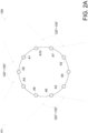
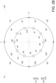
- FIGS. 2A and 2B are schematic diagrams of the antenna module 100 according to an embodiment of the present disclosure.
- the antenna module 100 comprises a plurality of antennas, for example, a first number of first antennas A1-A4 and a second number of second antennas A5-A10. More specifically, FIGS. 2A and 2B are top views according to a normal direction of the first plane P1, which depicts the distribution of the first antennas A1-A4 and the second antennas A5-A10 on the first plane P1.
- the first number is, e.g., "4"
- the second number is, e.g., "6". That is, the antenna module 100 comprises four first antennas A1-A4 and six second antennas A5-A1 0.
- Each of the first antennas A1-A4 may operate in the first frequency band F1 and the second frequency band F2.
- the first frequency band F1 ranges from the LB to the MB, for example, covering a frequency band of 400Hz to 2170MHz.
- the second frequency band F2 ranges from the HB to the UHB, for example, covering a frequency band of 3GHz to 5GHz.
- each of the second antennas A5-A10 may operate in the second frequency band F2.
- the directivity of an antenna may be described by the radiation pattern of the antenna.
- the antenna may be, for example, an omni-directional antenna, and its electromagnetic field radiation direction is substantially uniform in all directions of 360 degrees in a plane (such as, the first plane P1 in FIGS. 2A and 2B ).
- the antenna may be, for example, a directional antenna, and the directional antenna includes an uni-directional antenna and a semi-directional antenna.
- the uni-directional antenna focuses the radio frequency energy to a specific direction, according to its electromagnetic field radiation direction, furthermore, the gain of the directional antenna correspondingly increases, the antenna coverage distance increases, and the effective coverage angle decreases (in one embodiment, the effective coverage angle may be defined as the angular difference between the two half-power points in the radiation pattern).
- the effective coverage angle of the electromagnetic field radiation of the semi-directional antenna is greater than that of the uni-directional antenna. Since the semi-directional antenna has a larger coverage angle, only a small number of semi-directional antennas are needed to cover each direction of 360 degrees in a plane. In contrast, if a combination of uni-directional antennas is utilized, a large number of uni-directional antennas are required to cover each direction of 360 degrees in a plane.
- each of the first antennas A1-A4 and the second antennas A5-A10 is, for example, a uni-directional antenna. In another embodiment, each of the first antennas A1-A4 and the second antennas A5-A10 is, for example, a semi-directional antenna.
- the first antennas A1-A4 and the second antennas A5-A10 each has an effective coverage angle ranging from, for example, 120 degrees to 135 degrees. Alternatively, in yet another embodiment, the effective coverage angle of each of the first antennas A1-A4 and the second antennas A5-A10 may be substantially equal to 120 degrees.
- the first antennas A1-A4 and the second antennas A5-A10 are allocated on the first plane P1, and the first antennas A1-A4 and the second antennas A5-A10 are distributed on the circular position R1 of the first plane P1.
- the first plane P1 is divided into a first quadrant Q1, a second quadrant Q2, a third quadrant Q3, and a fourth quadrant Q4 according to the first axis X and the second axis Y
- the first antenna A1 is allocated in the first quadrant Q1, the first antenna A2 is allocated in the second quadrant Q2, the first antenna A3 is allocated in the third quadrant Q3, and the first antenna A4 is allocated in the fourth quadrant Q4.
- the first antenna A1 is allocated in a direction with an angle of 54 degrees with respect to the first axis X
- the first antenna A2 is allocated in a direction with an angle of -54 degrees with respect to the first axis X
- the first antenna A3 is allocated in a direction with an angle of -126 degrees with respect to the first axis X
- the first antenna A4 is allocated in a direction with an angle of 126 degrees with respect to the first axis X.
- the second antennas A5-A10 include two groups, the first group G1 includes three second antennas A5-A7, and the second group G2 includes three second antennas A8-A10.
- the first group G1 the second antenna A5 is allocated in the positive direction of the second axis Y
- the second antenna A7 is allocated in the second quadrant Q2
- the second antenna A6 is allocated in the third quadrant Q3.
- the second antenna A9 is allocated in the negative direction of the second axis Y
- the second antenna A10 is allocated in the first quadrant Q1
- the second antenna A8 is allocated in the fourth quadrant Q4.
- the second antenna A5 is allocated in a direction with an angle of 90 degrees with respect to the first axis X
- the second antenna A6 is allocated in a direction with an angle of -162 degrees with respect to the first axis X
- the second antenna A7 is allocated in a direction with an angle of -18 degrees with respect to the first axis X.
- the second antenna A8 is allocated in a direction with an angle of 162 degrees with respect to the first axis X
- the second antenna A9 is allocated in a direction with an angle of -90 degrees with respect to the first axis X
- the second antenna A10 is allocated in a direction with an angle of 18 degrees with respect to the first axis X.
- any adjacent two of the first antennas A1-A4 and the second antennas A5-A10 have an equal angle of 36 degrees. That is, the first antennas A1-A4 and the second antennas A5-A10 are uniformly distributed on the circular position R1 of the first plane P1.
- any two of the first antennas A1-A4 are not adjacent to each other, any two of the second antennas A5-A7 of the first group G1 are not adjacent to each other, and any two of the second antennas A8-A10 of the second group G2 are not adjacent to each other. That is, the first antennas A1-A4 and the second antennas A5-A10 are allocated alternately at the circular position R1 of the first plane P1.
- the second antenna A7 of the first group G1 and the second antenna A10 of the second group G2 are allocated between the first antenna A1 and the first antenna A2.
- the second antenna A9 of the second group G2 is allocated between the first antenna A2 and the first antenna A3.
- the second antenna A6 of the first group G1 and the second antenna A8 of the second group G2 are allocated between the first antenna A3 and the first antenna A4.
- the second antenna A5 of the first group G1 is allocated between the first antenna A4 and the first antenna A1.
- the allocating positions of the second antennas A5, A6 and A7 of the first group G1 may mirror to the allocating positions of the second antennas A9, A8 and A10 of the second group G2 according to the first axis X.
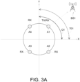
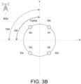
- FIGS. 3A-3C are schematic diagrams illustrating adaptively allocating the first antennas A1-A4 as the TX antennas and/or RX antennas for the first frequency band F1 in response to different base stations BS1-BS3.
- this embodiment shows that, in response to the base station BS1, each of the first antennas A1-A4 operates in the first frequency band F1 to receive the broadcast information (e.g., SSB sequence) of base station BS1 in LB or MB.
- the performance evaluation module 200 analyzes the signal strength and signal quality of the broadcast information received by the first antennas A1-A4, so as to evaluate the communication quality between the first antennas A1-A4 and the base station BS1 in the first frequency band F1.
- the direction of the first antenna A1 allocated in the first quadrant Q1 best fits the position and direction of the base station BS1, and the signal strength and signal quality of the broadcast information of the base station BS1 received by the first antenna A1 are the best. Therefore, the performance evaluation module 200 marks a region corresponding to the first quadrant Q1 as a base station region 701, and the base station region 701 is associated with the base station BS1.
- the decision module 300 is used to select the first antenna A1 of the first quadrant Q1 as the TX antenna for uplink communication of the first frequency band F1, and to establish a connection with the base station BS1 for uplink communication, through the first antenna A1.
- the first antenna A1 is also used as a RX antenna for the downlink communication in the first frequency band F1.
- the other three first antennas A2-A4 also serve as RX antennas for the downlink communication in the first frequency band F1.
- the first antennas A1-A4 form a "1T4R" configuration (i.e., 1-TX and 4-RX) for the first frequency band F1, which includes one TX antenna (i.e., the first antenna A1) and four RX antennas (i.e., the first antennas A1-A4).
- the embodiment in FIG. 3B corresponds to another base station BS2.
- the directivity of the first antenna A4 allocated in the fourth quadrant Q4 best fits the position and direction of the base station BS2, and the performance evaluation module 200 marks the region corresponding to the fourth quadrant Q4 as the base station region 704, which is associated with the base station BS2.
- the decision module 300 selects the first antenna A4 in the fourth quadrant Q4 as the TX antenna for uplink communication and the RX antenna for downlink communication in the first frequency band F1.
- the other three first antennas A1, A2 and A3 are also allocated as RX antennas for the downlink communication of the first frequency band F1, which forms a "1T4R" configuration of the first frequency band F1.
- the "1T4R" configuration of the embodiment in FIG. 3B includes one TX antenna (i.e., the first antenna A4) and four RX antennas (i.e., the first antennas A1-A4).
- the embodiment in FIG. 3C corresponds to another base station BS3.
- the directivity of the first antenna A3 allocated in the third quadrant Q3 best fits the position and direction of the base station BS3, and the performance evaluation module 200 marks the region corresponding to the third quadrant Q3 as the base station region 703, which is associated with the base station BS3.
- the decision module 300 selects the first antenna A3 of the third quadrant Q3 as the TX antenna for the uplink communication of the first frequency band F1, and establishes a connection of an uplink communication with the base station BS3, through the first antenna A3. All the first antennas A1-A4 are allocated as RX antennas for downlink communication in the first frequency band F1.
- the "1T4R" configuration of the first frequency band F1 is formed, which includes one TX antenna (i.e., the first antenna A3 ) and four RX antennas (i.e., the first antennas A1-A4).
- the decision module 300 in response to base stations BS1-BS3 of different directions and positions, selects one from the first antennas A1-A4 as the TX antennas for the uplink communication of the first frequency band F1, and all the first antennas A1-A4 are allocated as RX antennas for the downlink communication of the first frequency band F1, which forms a "1T4R" configuration of the first frequency band F1.
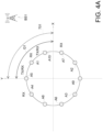
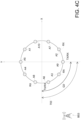
- FIGS. 4A-4C are schematic diagrams showing adaptively allocating the first antennas A1-A4 and the second antennas A5-A10 as the TX antennas and/or RX antennas of the second frequency band F2 in response to different base stations BS1-BS3.
- the performance evaluation module 200 marks base station regions according to the communication quality of the base stations BS1-BS3. According to the marked base station region, the decision module 300 selects two of the second antennas A5-A10 as the TX antennas for the uplink communication of the second frequency band F2.
- the embodiment in FIG. 4A corresponds to the base station BS1.
- the decision module 300 marks the region corresponding to the first quadrant Q1 as the base station region 701, and the base station region 701 is related to the base station BS1.
- the decision module 300 selects two of the second antennas A5-A10 which are mostly related to the base station region 701, as the TX antennas for uplink communication in the second frequency band F2.
- the selected two of the second antennas A5-A10 belong to the first group G1 and the second group G2 respectively. That is, the decision module 300 selects one antenna from the first group G1 and one antenna from the second group G2 as two TX antenna for the uplink communication of the second frequency band F2.
- FIG. 1 In the embodiment of FIG.
- the second antenna A5 of the first group G1 and the second antenna A10 of the second group G2 are most related to the base station region 701, and the second antennas A5 and A10 are selected as two TX antenna for the uplink communication of the second frequency band F2.
- the second antennas A5 and A10 are also used as RX antennas for the downlink communication of the second frequency band F2.
- the decision module 300 selects the first antenna A4 and A1, which are adjacent to the second antenna A5, as the RX antenna for the downlink communication of the second frequency band F2, to form a "2T4R" configuration of the second frequency band F2.
- the "2T4R" configuration includes two TX antennas (i.e., the second antennas A5 and A10) and four RX antennas (i.e., the second antennas A5 and A10 and the first antennas A4 and A1).
- the decision module 300 selects the first antenna A1 and the second antenna A7, which are adjacent to the second antenna A10, as RX antennas for the downlink communication of the second frequency band F2.
- the "2T4R" configuration of the second frequency band F2 comprises two TX antennas (i.e., the second antennas A5 and A10) and four RX antennas (i.e., the second antennas A5, A7, and A10, and the first Antenna A1).
- the embodiment in FIG. 4B corresponds to another base station BS2.
- the decision module 300 marks the region, which corresponds to the fourth quadrant Q4, as the base station region 704, and the base station region 704 is related to the base station BS2.
- the decision module 300 selects one antenna from the first group G1 and selects one antenna from the second group G2 of the second antennas A5-A10 as two TX antennas for the uplink communication of the second frequency band F2.
- the second antenna A5 of the first group G1 and the second antenna A8 of the second group G2 are most related to the base station region 704, and the second antennas A5 and A8 are selected as TX antennas for the uplink communication of the second frequency band F2.
- the second antennas A5 and A8 are also used as RX antennas for the downlink communication of the second frequency band F2.
- the decision module 300 further selects the first antenna A4 and A1, which are adjacent to the second antenna A5, as two RX antennas for the downlink communication of the second frequency band F2.
- the "2T4R" configuration in the embodiment of FIG. 4B comprises two TX antennas (i.e., the second antennas A5 and A8) and four RX antennas (i.e., the second antennas A5 and A8, and the first antenna A4 and A1).
- the first antenna A1 and the second antenna A6, which are adjacent to the second antenna A8, are selected as two RX antennas for downlink communication in the second frequency band F2.
- the "2T4R" configuration of the second frequency band F2 comprises two TX antennas (i.e., the second antennas A5 and A8) and four RX antennas (i.e., the second antennas A5, A6, and A8, and the first Antenna A4).
- the embodiment of FIG. 4C corresponds to another base station BS3.
- the region corresponding to the third quadrant Q3 is marked as the base station region 703, which is associated with the base station BS3.
- the second antenna A6 of the first group G1 and the second antenna A9 of the second group G2 are most related to the base station region 703, and the second antennas A6 and A9 are selected as two TX antennas of the uplink communication of the second frequency band F2.
- the second antennas A6 and A9 are also allocated as RX antennas for the downlink communication of the second frequency band F2.
- the first antennas A2 and A3 adjacent to the second antenna A9 are selected as RX antennas for downlink communication of the second frequency band F2.
- the "2T4R" configuration of the embodiment of FIG. 4C comprises two TX antennas (i.e., the second antennas A6 and A9) and four RX antennas (i.e., the second antennas A6 and A9 and the first antennas A2 and A3).
- the first antenna A3 and the second antenna A8, which are adjacent to the second antenna A6, are selected as RX antennas for downlink communication in the second frequency band F2.
- the "2T4R" configuration of the second frequency band F2 comprises two TX antennas (i.e., the second antennas A6 and A9) and four RX antennas (i.e., the second antennas A6, A8, and A9 and the first Antenna A3).
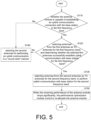
- FIG. 5 is a flow diagram of an embodiment of an allocation method for the communication device 1000 of the present disclosure.
- the steps of the flow diagram of FIG. 5 correspond to the embodiments in FIGS. 3A-3C and FIGS. 4A-4C .
- the communication device 1000 preliminarily determines whether the antenna module 100 is capable of establishing a connection with the base stations BS1-BS3 in the first frequency band F1. That is, preliminarily determining that, whether it is possible to establish an uplink communication connection with the base stations BS1-BS3 in the first frequency band F1 through the first antennas A1-A4. If the determination result is positive (i.e., "Yes"), executing step S120. If the determination result is negative (i.e., "No"), execute step S140.
- the communication device 1000 selects the most suitable one of the first antennas A1-A4 and one of the base stations BS1-BS3 with the best communication quality to perform uplink communication. More specifically, the communication device 1000 controls each of the first antennas A1-A4 to operate in the first frequency band F1, so as to receive broadcast information of the base stations BS1-BS3 at the LB or MB.
- the performance evaluation module 200 analyzes the signal strength and signal quality of the broadcast information received by the first antennas A1-A4 in the first frequency band F1, so as to evaluate the communication quality.
- the decision module 300 selects one among the base stations BS1-BS3 with the best communication quality, and selects the most suitable one from the first antenna A1-A4 to establish the uplink communication connection with the selected base station.
- the performance evaluation module 200 analyzes that, the base station BS1 has the best communication quality in the current environment, and the performance evaluation module 200 marks the base station region 701 according to the position of the base station BS1, and the base station region 701 corresponds to the first quadrant Q1. Moreover, the performance evaluation module 200 analyzes that, the first antenna A1 allocated in the first quadrant Q1 has the best communication quality with the base station BS1, and the decision module 300 selects the first antenna A1 to establish a connection for uplink communication with the base station BS1 in the first frequency band F1.
- the first antenna A1 serves as the TX antenna of the first frequency band F1 and performs uplink communication with the base station BS1 in the first frequency band F1.
- the first antenna A1 serves as a RX antenna of the first frequency band F1 at the same time.
- the other first antennas i.e., the first antennas A2-A4 are also used as RX antennas of the first frequency band F1.
- the first antennas A1-A4 form a "1T4R" configuration of the first frequency band F1.
- step S120 if it successfully performs uplink communication in the first frequency band F1 with the base station BS1 using the selected first antenna A1, and successfully performs downlink communication in the second frequency band F2 with the base station BS1 using the first antennas A1-A4, then execute step S130.
- step S130 according to the base station BS1 and the first antenna A1 selected in step S120, the communication device 1000 selects two from the second antennas A5-A10 as the TX antenna of the second frequency band F2, which are used to perform uplink communication with the base station BS1 in the second frequency band F2.
- the decision module 300 selects two from the second antennas A5-A10, which are most related to the base station region 701, that is, the second antenna A5 of the first group G1 and the second antenna A10 of the second group G2.
- the second antennas A5 and A10 serve as the TX antennas of the second frequency band F2 for uplink communication with the base station BS1, and the second antennas A5 and A10 also serve as the RX antennas of the second frequency band F2 for downlink communication.
- the decision module 300 further selects the first antenna A4 and A1, which are adjacent to the second antenna A5, as the RX antennas for the downlink communication of the second frequency band F2.
- the second antennas A5 and A10 and the first antennas A4 and A1 form a "2T4R" configuration of the second frequency band F2.
- the decision module 300 selects the first antenna A1 and the second antenna A7, which are adjacent to the second antenna A10, as RX antennas for the downlink communication of the second frequency band F2.
- the second antennas A5 , A7 and A10 and the first antenna A1 form a "2T4R" configuration of the second frequency band F2 .
- step S150 is performed.
- step S150 the performance evaluation module 200 calculates the spectrum efficiency of each antenna of the "1T4R" configuration of the first frequency band F1 and each antenna of the "2T4R” configuration of the second frequency band F2, so as to evaluate the receiving performance of the antenna module 100.
- the performance optimization module 400 re-allocates the antenna module 100, so as to re-allocate the antennas of the "1T4R” configuration of the first frequency band F1 and/or re-allocate the antennas of the "2T4R” configuration of the second frequency band F2. Receiving performance of the antenna module 100 may thus be recovered.
- the performance optimization module 400 re-allocates the antennas of the "2T4R" configuration of the second frequency band F2.
- the performance evaluation result of the performance evaluation module 200 shows that, the connection between the antenna module 100 and the base station BS1 is terminated. Then, the performance optimization module 400 re-allocates antennas of the "1T4R" configuration of the first frequency band F1. For example, step S120 is re-executed, evaluating that communication quality of another base station BS2 is better, and marking another base station region 704. Then the performance optimization module 400 selects the first antenna A4 allocated in the fourth quadrant Q4 to connect with the base station BS2 for uplink communication, and the first antenna A4 is used as the TX antenna and the RX antenna of the first frequency band F1.
- the performance optimization module 400 selects the second antennas A5 and A8, which are most related to the base station region 704, as the TX antenna and the RX antenna of the second frequency band F2. Then, selecting the first antennas A1 and A4, which are adjacent to the second antenna A5, as RX antennas for the second frequency band F2.
- step S110 determines whether the antenna module 100 may merely establish connections with the base stations BS1-BS3 in the second frequency band F2 (i.e., it is only possible to establish uplink communication connections with the base stations BS1-BS3 in the second frequency band F2 through the second antennas A5-A10), and then executing step S140.
- step S120 if the uplink communication of the first frequency band F1 is not successfully performed with the base station through one of the first antennas A1-A4, then step S140 is executed.
- step S140 taking the second antennas A5-A10 to receive the HB/UHB broadcast information of the base station BS1-BS3 in the second frequency band F2, and using the performance evaluation module 200 to analyze the received signal strength and signal quality by the second antennas A5-A10. That is, the communication quality of each of the second antennas A5-A10 is evaluated in a "round-robin" manner, so as to select suitable ones from the second antennas A5-A10 for uplink communication.
- the base station BS1 in the current environment is related to the base station region 701 of the first quadrant Q1, and the decision module 300 selects the second antennas A5 and A10 which are most related to the base station region 701, from the second antennas A5-A10.
- step S130 is executed, using the second antennas A5 and A10 as the TX antennas of the second frequency band F2 to perform uplink communication with the base station BS1 in the second frequency band F2.
Landscapes
- Engineering & Computer Science (AREA)
- Computer Networks & Wireless Communication (AREA)
- Signal Processing (AREA)
- Mobile Radio Communication Systems (AREA)
Applications Claiming Priority (1)
| Application Number | Priority Date | Filing Date | Title |
|---|---|---|---|
| TW112119341A TWI881352B (zh) | 2023-05-24 | 2023-05-24 | 具有多天線的通訊裝置、及其天線的配置方法 |
Publications (1)
| Publication Number | Publication Date |
|---|---|
| EP4472097A1 true EP4472097A1 (fr) | 2024-12-04 |
Family
ID=91247495
Family Applications (1)
| Application Number | Title | Priority Date | Filing Date |
|---|---|---|---|
| EP24177995.8A Pending EP4472097A1 (fr) | 2023-05-24 | 2024-05-24 | Dispositif de communication à antennes multiples et procédé d'attribution pour lesdites antennes |
Country Status (4)
| Country | Link |
|---|---|
| US (1) | US20240396233A1 (fr) |
| EP (1) | EP4472097A1 (fr) |
| AU (1) | AU2024203430B2 (fr) |
| TW (1) | TWI881352B (fr) |
Citations (3)
| Publication number | Priority date | Publication date | Assignee | Title |
|---|---|---|---|---|
| JP2014147060A (ja) * | 2013-01-28 | 2014-08-14 | Electronics And Telecommunications Research Institute | 無線通信システムにおける複数の無線チャネルを利用して方向探索及び無線通信を実行する方法及び装置 |
| US20180191421A1 (en) * | 2017-01-05 | 2018-07-05 | Samsung Electronics Co., Ltd. | Electronic device, method for controlling thereof and computer-readable recording medium |
| WO2023043559A1 (fr) * | 2021-09-14 | 2023-03-23 | Qualcomm Incorporated | Techniques de sélection d'antennes pour communications sans fil en liaison montante et en liaison descendante |
Family Cites Families (4)
| Publication number | Priority date | Publication date | Assignee | Title |
|---|---|---|---|---|
| TWI664832B (zh) * | 2017-12-14 | 2019-07-01 | 財團法人工業技術研究院 | 通訊系統、協調裝置及干擾控制方法 |
| US11963150B2 (en) * | 2018-11-01 | 2024-04-16 | Qualcomm Incorporated | Positioning enhancements for locating a mobile device in a wireless network |
| CN115767643A (zh) * | 2021-09-06 | 2023-03-07 | 北京小米移动软件有限公司 | 小区重选的方法、装置、电子设备及存储介质 |
| CN114335996B (zh) * | 2021-12-30 | 2024-08-27 | 京信通信技术(广州)有限公司 | 多扇区天线 |
-
2023
- 2023-05-24 TW TW112119341A patent/TWI881352B/zh active
-
2024
- 2024-05-22 US US18/671,216 patent/US20240396233A1/en active Pending
- 2024-05-23 AU AU2024203430A patent/AU2024203430B2/en active Active
- 2024-05-24 EP EP24177995.8A patent/EP4472097A1/fr active Pending
Patent Citations (3)
| Publication number | Priority date | Publication date | Assignee | Title |
|---|---|---|---|---|
| JP2014147060A (ja) * | 2013-01-28 | 2014-08-14 | Electronics And Telecommunications Research Institute | 無線通信システムにおける複数の無線チャネルを利用して方向探索及び無線通信を実行する方法及び装置 |
| US20180191421A1 (en) * | 2017-01-05 | 2018-07-05 | Samsung Electronics Co., Ltd. | Electronic device, method for controlling thereof and computer-readable recording medium |
| WO2023043559A1 (fr) * | 2021-09-14 | 2023-03-23 | Qualcomm Incorporated | Techniques de sélection d'antennes pour communications sans fil en liaison montante et en liaison descendante |
Also Published As
| Publication number | Publication date |
|---|---|
| AU2024203430A1 (en) | 2024-12-12 |
| US20240396233A1 (en) | 2024-11-28 |
| AU2024203430B2 (en) | 2025-12-04 |
| TWI881352B (zh) | 2025-04-21 |
| TW202448017A (zh) | 2024-12-01 |
Similar Documents
| Publication | Publication Date | Title |
|---|---|---|
| EP2679058B1 (fr) | Configuration de la distribution de puissance dans les zones de coopération de réseaux de communications cellulaires | |
| Halbauer et al. | 3D beamforming: Performance improvement for cellular networks | |
| Muirhead et al. | A survey of the challenges, opportunities and use of multiple antennas in current and future 5G small cell base stations | |
| Koppenborg et al. | 3D beamforming trials with an active antenna array | |
| CA2534581C (fr) | Methode et appareillage de couverture et d'amelioration du debit d'un systeme de communication sans fil | |
| JP5319840B2 (ja) | 無線基地局とユーザ機器との間の通信のための無線基地局および関連する方法 | |
| US8983548B2 (en) | Multi-beam co-channel Wi-Fi access point | |
| US20110032849A1 (en) | Systems and methods for mitigating interference between access points | |
| US20110009105A1 (en) | Self-organizing networks using directional beam antennas | |
| KR101954284B1 (ko) | 실내 무선 네트워크를 위한 셀내 주파수 재사용을 위한 방법 및 기저대역 유닛 | |
| US20230208485A1 (en) | Improvements for beamformed transmissions in wireless communication networks | |
| JP5574738B2 (ja) | 無線通信システム、無線基地局装置、制御装置および無線端末装置 | |
| US20200303835A1 (en) | Antenna Apparatus And Communications Apparatus | |
| CN106134235B (zh) | 用于指示小区分裂模式的方法及装置 | |
| Soorki et al. | Joint access point deployment and assignment in mmWave networks with stochastic user orientation | |
| US20200229003A1 (en) | Access Point Device and Communication Method | |
| CN103826233B (zh) | 融合组网配置方法及装置 | |
| US20190132742A1 (en) | Antenna system and antenna system adjustment method | |
| CN113273096B (zh) | 天线阵列组选择和天线阵列选择的方法和装置 | |
| EP4472097A1 (fr) | Dispositif de communication à antennes multiples et procédé d'attribution pour lesdites antennes | |
| Balachandran et al. | Flexible duplex in FDD spectrum | |
| WO2024166765A1 (fr) | Système de relais de communication, procédé de relais de communication, et programme | |
| US10848984B1 (en) | Adaptive sectoring of a wireless base station | |
| KR20210060339A (ko) | 통신망에서 클러스터를 구성하는 방법 및 장치 | |
| Maltsev et al. | Performance evaluation of interference mitigation techniques in the overlaying MmWave small cell network |
Legal Events
| Date | Code | Title | Description |
|---|---|---|---|
| PUAI | Public reference made under article 153(3) epc to a published international application that has entered the european phase |
Free format text: ORIGINAL CODE: 0009012 |
|
| STAA | Information on the status of an ep patent application or granted ep patent |
Free format text: STATUS: THE APPLICATION HAS BEEN PUBLISHED |
|
| AK | Designated contracting states |
Kind code of ref document: A1 Designated state(s): AL AT BE BG CH CY CZ DE DK EE ES FI FR GB GR HR HU IE IS IT LI LT LU LV MC ME MK MT NL NO PL PT RO RS SE SI SK SM TR |
|
| STAA | Information on the status of an ep patent application or granted ep patent |
Free format text: STATUS: REQUEST FOR EXAMINATION WAS MADE |
|
| 17P | Request for examination filed |
Effective date: 20250604 |