EP4473853A1 - Elektronische zigarette mit auswechselbarer e-flüssigkeitskartusche - Google Patents
Elektronische zigarette mit auswechselbarer e-flüssigkeitskartusche Download PDFInfo
- Publication number
- EP4473853A1 EP4473853A1 EP23192917.5A EP23192917A EP4473853A1 EP 4473853 A1 EP4473853 A1 EP 4473853A1 EP 23192917 A EP23192917 A EP 23192917A EP 4473853 A1 EP4473853 A1 EP 4473853A1
- Authority
- EP
- European Patent Office
- Prior art keywords
- liquid
- chamber
- atomizing
- disposed
- shell
- Prior art date
- Legal status (The legal status is an assumption and is not a legal conclusion. Google has not performed a legal analysis and makes no representation as to the accuracy of the status listed.)
- Pending
Links
Images






Classifications
-
- A—HUMAN NECESSITIES
- A24—TOBACCO; CIGARS; CIGARETTES; SIMULATED SMOKING DEVICES; SMOKERS' REQUISITES
- A24F—SMOKERS' REQUISITES; MATCH BOXES; SIMULATED SMOKING DEVICES
- A24F40/00—Electrically operated smoking devices; Component parts thereof; Manufacture thereof; Maintenance or testing thereof; Charging means specially adapted therefor
- A24F40/40—Constructional details, e.g. connection of cartridges and battery parts
- A24F40/42—Cartridges or containers for inhalable precursors
-
- A—HUMAN NECESSITIES
- A24—TOBACCO; CIGARS; CIGARETTES; SIMULATED SMOKING DEVICES; SMOKERS' REQUISITES
- A24F—SMOKERS' REQUISITES; MATCH BOXES; SIMULATED SMOKING DEVICES
- A24F40/00—Electrically operated smoking devices; Component parts thereof; Manufacture thereof; Maintenance or testing thereof; Charging means specially adapted therefor
- A24F40/10—Devices using liquid inhalable precursors
-
- A—HUMAN NECESSITIES
- A24—TOBACCO; CIGARS; CIGARETTES; SIMULATED SMOKING DEVICES; SMOKERS' REQUISITES
- A24F—SMOKERS' REQUISITES; MATCH BOXES; SIMULATED SMOKING DEVICES
- A24F40/00—Electrically operated smoking devices; Component parts thereof; Manufacture thereof; Maintenance or testing thereof; Charging means specially adapted therefor
- A24F40/40—Constructional details, e.g. connection of cartridges and battery parts
- A24F40/46—Shape or structure of electric heating means
-
- A—HUMAN NECESSITIES
- A24—TOBACCO; CIGARS; CIGARETTES; SIMULATED SMOKING DEVICES; SMOKERS' REQUISITES
- A24F—SMOKERS' REQUISITES; MATCH BOXES; SIMULATED SMOKING DEVICES
- A24F40/00—Electrically operated smoking devices; Component parts thereof; Manufacture thereof; Maintenance or testing thereof; Charging means specially adapted therefor
- A24F40/40—Constructional details, e.g. connection of cartridges and battery parts
- A24F40/48—Fluid transfer means, e.g. pumps
- A24F40/485—Valves; Apertures
-
- A—HUMAN NECESSITIES
- A24—TOBACCO; CIGARS; CIGARETTES; SIMULATED SMOKING DEVICES; SMOKERS' REQUISITES
- A24F—SMOKERS' REQUISITES; MATCH BOXES; SIMULATED SMOKING DEVICES
- A24F40/00—Electrically operated smoking devices; Component parts thereof; Manufacture thereof; Maintenance or testing thereof; Charging means specially adapted therefor
- A24F40/40—Constructional details, e.g. connection of cartridges and battery parts
- A24F40/48—Fluid transfer means, e.g. pumps
Definitions
- the disclosure relates to the field of electronic cigarettes, and more particularly, to an electronic cigarette comprising a replaceable e-liquid cartridge.
- a conventional electronic cigarette typically includes a cartridge and a battery body, which can be assembled as a unit or connected together with magnets for easy detachment.
- the cartridge is used to store e-liquid and generate smoke through heating, while the battery body supplies power.
- the cartridge contains a chamber for storing e-liquid. However, the capacity of the chamber is restricted, causing the cartridge to have a finite operational duration. Once the e-liquid is used up, the cartridge needs to be replaced and cannot be recycled, resulting in higher costs and affecting the overall user satisfaction.
- certain cartridges come with e-liquid injection holes. Once the e-liquid inside the cartridge is used up, more e-liquid can be injected through these e-liquid injection holes for the cartridge to be reused.
- the e-liquid injection holes are not tightly sealed, leading to issues with e-liquid leakage.
- carrying extra e-liquid is inconvenient.
- external leakage can contaminate the cartridge, resulting in an unsatisfied user experience.
- the e-liquid can undergo oxidation and deterioration.
- the disclosure provides an electronic cigarette comprising a replaceable e-liquid cartridge.
- the electronic cigarette comprises an atomizing body and an e-liquid cartridge; the atomizing body comprises an atomizing core and an e-liquid chamber; the atomizing core is configured to absorb and heat the e-liquid for vaporization; and the e-liquid cartridge is detachably connected to the atomizing body to supply the e-liquid to the e-liquid chamber.
- the atomizing body further comprises a first shell and a base; the e-liquid chamber is defined by the first shell and the base; one end of the first shell comprises a mouthpiece for inhalation; the mouthpiece comprises a smoking opening; the base is disposed at the other end of the first shell, away from the smoking opening; and the e-liquid cartridge is detachably connected to the base.
- the e-liquid cartridge comprises an exposed end; and the base comprises a first through-hole into which the exposed end of the e-liquid cartridge is inserted, so that the liquid-cartridge is fixedly connected to the base.
- the first through-hole is defined by a wall; the wall comprises an internal threading or a hollow threaded connector, so that the e-liquid cartridge is threaded onto the base.
- the atomizing body further comprises an e-liquid guide portion through which the e-liquid cartridge is connected to the e-liquid chamber;
- the e-liquid guide portion comprises a sealing member functioning as a division between the e-liquid cartridge and the e-liquid chamber;
- the sealing member comprises a driving assembly; and the driving assembly is activated to induce the motion of the sealing member, thereby opening or closing the e-liquid guide portion.
- the driving assembly comprises a driving member that is activated to induce the motion of the sealing member; and at least a part of the driving member is exposed on the first shell.
- the driving assembly further comprises an elastic member used to reset the sealing member;
- the driving member comprises a hand-push section and a push rod;
- the push rod is disposed between the hand-push section and the sealing member;
- the hand-push section is exposed on the outside of the first shell; one end of the elastic member is secured to the atomizing body; and the other end of the elastic member is connected to the hand-push section or the sealing member.
- the hand-push section comprises a press-type cover;
- the press-type cover comprises a main body and a sidewall protruding along the edge of the main body;
- the first shell further comprises a recess inside, with a protruding element formed within the recess; an annular groove is formed between the outer edge of the recess and protruding element; and at least a portion of the sidewall is slidable into the annular groove.
- the press-type cover needs to be rotated to a predefined position to active a pressing mechanism and thereby activate the movement of the sealing member;
- the inner side of the sidewall comprises at least two strip-like blocks protruding along the circumference of the sidewall; one end of the at least two strip-like blocks protrudes in the axial direction of the sidewall and away from the main body, forming a limited-stop protrusion;
- a gap is formed between every two adjacent strip-like blocks;
- a peripheral wall of the protruding element comprises at least one ridge used to align with the corresponding gap;
- the at least one ridge is slidable into the corresponding gap; when sliding toward one end of the at least two strip-like blocks, the at least one ridge is stopped by the corresponding limited-stop protrusion; when sliding toward the other end of the at least two strip-like blocks, the at least one ridge is stopped by the adjacent limited-stop protrusions to align with the corresponding gap.
- the atomizing body further comprises a sealing plug disposed on the base and within the first shell to seal the e-liquid chamber.
- the sealing plug comprises a second through-hole; the first through-hole is connected to the second through-hole to constitute the e-liquid guide portion; the sealing member abuts against on the side of the sealing plug that is directed towards the base to seal the second through-hole.
- the first shell further comprises a smoke guide tube communicating with the smoking opening; the atomizing core is disposed within the first shell to heat and atomize the e-liquid; the e-liquid chamber surrounds the atomizing core; the base is disposed at one end of the first shell, away from the smoking opening; the atomizing core comprises an atomizing tube and a heating core disposed inside the atomizing tube; the atomizing tube comprises an e-liquid inlet disposed corresponding to the e-liquid chamber and the heating core; the atomizing tube is connected between the smoke guide tube and the base; the base further comprises an air inlet communicating with the atomizing tube; the electronic cigarette further comprises a first conductive electrode disposed on the outside of the base; alternatively, the atomizing tube comprises one end sealed and extending from the base; a peripheral wall of the sealed end comprises an air inlet; at least a portion of the air inlet is exposed on the outside of the base; and the first conductive electrode is disposed on the sealed end of the
- the electronic cigarette further comprises a battery assembly;
- the battery assembly comprises a second shell and a battery cell;
- the second shell comprises a first chamber and a second chamber;
- the e-liquid cartridge is disposed within the first chamber;
- the battery cell is disposed within the second chamber; the first shell and the second shell are fixedly connected or integrally formed.
- one end of the first chamber is disposed away from the atomizing body and comprises a first opening; the electronic cigarette further comprises a sealing cap disposed on the first opening to open or close the first chamber; one end of the e-liquid cartridge is directed towards the first opening and comprises a knob switch used for detaching or attaching the e-liquid cartridge from the first opening; and/or one end of the second chamber is disposed away from the atomizing body and comprises a second opening; the battery cell is inserted through the second opening and is detachably disposed within the second chamber; the bottom part of the battery cell is disposed away from the atomizing body and used to seal the second opening.
- the second shell further comprises a third chamber used to hold part of the atomizing body; the first chamber and the second chamber are disposed side by side, and the third chamber is disposed at the same end of the first chamber and the second chamber, facing the atomizing body; preferably, the atomizing body is detachably disposed within the third chamber; one end of the battery cell, oriented towards the third chamber, comprises a second conductive electrode.
- the e-liquid cartridge comprises the atomizing body and an e-liquid cartridge;
- the atomizing body comprises the atomizing core and an e-liquid chamber;
- the atomizing core is disposed in the atomizing body to absorb and heat the e-liquid for vaporization;
- the e-liquid chamber is disposed in the atomizing body;
- the e-liquid cartridge is detachably connected to the atomizing body to supply the e-liquid to the e-liquid chamber; adding the e-liquid cartridge to the electronic cigarette makes refilling the e-liquid chamber easier and more convenient, anytime and anywhere; by incorporating the design, the e-liquid cartridge can be reused, enhancing the efficiency of the electronic cigarette and catering to individual preferences; as a result, the electronic cigarette achieves prolonged sustainability in terms of usage duration; the process of refilling the e-liquid chamber is swift, user-friendly, hygienic, and seamless, preventing leaks effectively; furthermore, the disclosure protects the e-
- Atomizing body 11. First shell; 111. Mouthpiece; 53. Smoking opening; 54. Protrusion; 112. Protruding element; 114. Smoke guide tube; 1121. Ridge; 113. Annular groove; 12. Driving assembly; 121. Driving member; 122. Elastic member; 1211. Hand-push section; 1212. Push rod; 1211a. Main body; 1211b. Sidewall; 1211c. Strip-like block; 1211d. Limited-stop protrusion; 1211e. Gap; 13. Sealing member; 14. Base; 141. First through-hole; 142. Air inlet; 15. Sealing plug; 151. Second through-hole; 16. Atomizing core; 161. Atomizing tube; 162. Heating core; 163.
- connection should be understood in a broad sense. For example, they could refer to direct connection or indirect connection through an intermediary medium. It could encompass either an internal linkage between two components or an interactive relationship between the components, unless otherwise specifically restricted.
- connection should be understood in a broad sense. For example, they could refer to direct connection or indirect connection through an intermediary medium. It could encompass either an internal linkage between two components or an interactive relationship between the components, unless otherwise specifically restricted.
- connection should be understood in a broad sense. For example, they could refer to direct connection or indirect connection through an intermediary medium. It could encompass either an internal linkage between two components or an interactive relationship between the components, unless otherwise specifically restricted.
- connection should be understood in a broad sense. For example, they could refer to direct connection or indirect connection through an intermediary medium. It could encompass either an internal linkage between two components or an interactive relationship between the components, unless otherwise specifically restricted.
- connection should be understood in a broad sense. For example, they could refer to direct connection or indirect connection through an intermediary medium. It could encompass either an internal
- fluid connection implies that fluid (including liquid and/or gas) can flow from one component to another.
- connection between two components can denote direct alignment, such as when at least part of two holes align, or it can involve an intermediary medium.
- the disclosure provides an electronic cigarette comprising a replaceable e-liquid cartridge.
- the electronic cigarette comprises an atomizing body 10 and an e-liquid cartridge 20.
- the atomizing body 10 comprises an atomizing core 16 and an e-liquid chamber 51.
- the atomizing core 16 is disposed in the atomizing body 10 to absorb and heat the e-liquid for vaporization.
- the e-liquid chamber 51 is disposed in the atomizing body 10.
- the e-liquid cartridge 20 is detachably connected to the atomizing body 10 to supply the e-liquid to the e-liquid chamber 51.
- the e-liquid cartridge 20 functioning as a storage unit, often referred to as a reservoir or container, stores the e-liquid for the electronic cigarette.
- the e-liquid is commonly utilized as an alternative to conventional tobacco products and optionally comprises flavoring agents or additives to enhance the taste.
- the electronic cigarette provides a range of flavors and tastes, tailoring to consumer choices.
- the electronic cigarette also solves the problems linked to conventional refillable electronic cigarettes, where preparing e-liquid containers and using specialized tools for replenishment becomes a cumbersome task. This convenient becomes pronounced when carrying these items while traveling.
- the refilling process could lead to air entering the e-liquid container, thereby contaminating the e-liquid and impacting its taste, and resulting in health concerns due to the introduction of unfamiliar substances.
- the shape of the e-liquid cartridge 20 is not rigidly defined, as long as it fulfills the criteria of being detachable and ensuring a secure seal.
- the e-liquid cartridge 20 is in the shape of a cylinder.
- a cylindrical e-liquid cartridge 20 of the equivalent dimensions can accommodate more liquid due to its larger internal space and storage capacity. This configuration promotes convenience in storage and usage.
- the manufacturing and assembly process of cylindrical e-liquid cartridges are simpler in comparison to other shapes, thereby enhancing production efficiency and reducing costs.
- the atomizing body 10 further comprises a first shell 11 and a base 14.
- One end of the first shell 11 comprises a mouthpiece 111 for inhalation, and the base 14 is disposed at the other end of the first shell 11.
- the e-liquid cartridge 20 is detachably connected to the base 14.
- the e-liquid chamber 51 is defined by the first shell 11 and the base 14, so as to surround the atomizing core 16; the e-liquid cartridge 20 is connected to the base 14 to establish a connection that allows communication between the e-liquid cartridge 20 and the e-liquid chamber 51, making refilling the e-liquid chamber 51 easier.
- the mouthpiece 111 functions as a passage for users to inhale the vapor; the mouthpiece comprises a smoking opening 53 connected to the atomizing core 16; the vapor produced by heating the e-liquid in the atomizing core 16 is released through the smoking opening 53 and enters the user's mouth.
- the base 14 is detachably connected to the e-liquid cartridge 20 in a plurality of manners, comprising threaded connections, magnetic connections, snap-fit connections, or a combination thereof.
- the e-liquid cartridge 20 is threaded onto the base 14. This threaded connection endures tension and vibration, mitigating the risk of loosening due to external forces and preventing e-liquid leakage.
- the e-liquid cartridge 20 comprises an exposed end; the base 14 comprises a first through-hole 141 into which the exposed end of the e-liquid cartridge 20 is inserted, so that the liquid-cartridge is fixedly connected to the base.
- the base 14 further comprises a protrusion 54 that is in the shape of a hollow cylinder, extending outward.
- the protrusion 54 which can be part of the base 14, is connected to the first through-hole 141.
- the protrusion 54 is used to firmly secure the e-liquid cartridge 20, ensuring stability and enhancing sealing by maximizing contact.
- the protrusion 54 comprises an internal threading that threads into the e-liquid cartridge 20, preventing the e-liquid leakage.
- the outer circumference of the protrusion 54 comprises external threading, allowing the e-liquid cartridge 20 to be threaded onto the protrusion 54.
- a threaded connector 17 is disposed within the first through-hole 141.
- the threaded connector 17 is hollow.
- the e-liquid cartridge 20 is threaded onto the base 14 through the threaded connector 17.
- the threaded connector 17 is disposed on a wall surrounding the first through-hole 141, achieving a snug fit with the base 14 through an interference fit.
- the threaded connector 17 comprises metal or plastic, preferably metal.
- Metal threaded connectors outperform plastic threaded connectors 17 in strength, durability, and resistance to chemicals. Additionally, the metal threaded connectors withstand higher pressure and tension, resulting in a longer lifespan. With prolonged use, the metal threaded connectors maintain sealing performance by avoiding dissolution or deformation, thereby ensuring a high-quality sealed connection.
- the atomizing body 10 further comprises an e-liquid guide portion 52 through which the e-liquid cartridge 20 is connected to the e-liquid chamber 51.
- the e-liquid guide portion 52 comprises a sealing member 13 functioning as a division between the e-liquid cartridge 20 and the e-liquid chamber 51.
- the sealing member 13 comprises a driving assembly 12 that is activated to induce the motion of the sealing member 13, thereby opening or closing the e-liquid guide portion 52.
- the sealing member 13 is in the shape of a sheet or a block, as long as it ensures an effective seal within the e-liquid guide portion 52.
- the sealing member 13 comprises high-density elastic colloids, plastic, or metal.
- the term "elastic colloids”, as used herein, refers to materials that deform under an external force and promptly return to their original shape once the external force is removed. This property enhances the sealing effectiveness of the sealing member 13, preventing the e-liquid from flowing freely between the e-liquid cartridge and the e-liquid chamber when the e-liquid guide portion 52 is closed.
- the elastic colloids comprise natural rubber, synthetic rubber, polypropylene, and polyethylene.
- the sealing member 13 comprises food-grade rubber.
- the sealing member 13 is disposed near the first through-hole 141.
- the e-liquid guide portion 52 is a passage used to connect the e-liquid cartridge and the e-liquid chamber.
- the term "passage" comprises both an inlet and an outlet.
- the passage is cylindrical, conical, frustoconical, or curved, providing a space for fluid flow.
- the driving assembly 12 comprises a driving member 121 that is activated to induce the motion of the sealing member 13. At least a part of the driving member 121 is exposed on the first shell 11, allowing users to manually manipulate the sealing member to regulate the opening and closing of the e-liquid guide portion 52, without the need to open the first shell 11.
- the driving member 121 comprises a hand-push section 1211 and a push rod 1212.
- the push rod 1212 is connected between the hand-push section 1211 and the sealing member 13.
- the hand-push section 1211 is exposed on the outside of the first shell 11.
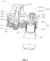
- the hand-push section 1211 is operated by manual pressing (as shown in FIGS. 3 and 8 ), or by sliding (as shown in FIGS. 11-12 ).
- the hand-push section 1211 comprises a press-type cover.
- the press-type cover comprises a main body 1211a and a sidewall 1211b protruding along the edge of the main body 1211a.
- the first shell 11 further comprises a recess inside, with a protruding element 112 formed within the recess.
- An annular groove 113 is formed between the outer edge of the recess and the protruding element 112. A portion of the sidewall 1211b is slidable into the annular groove 113.
- the sidewall 1211b moves longitudinally along the annular groove 113, applying force through the pressing action.
- the inner side of the sidewall 1211b comprises at least two strip-like blocks 1211c protruding along the circumference of the sidewall 1211b.
- One end of the at least two strip-like blocks 1211c protrudes in the axial direction of the sidewall 1211b and away from the main body 1211a, forming a limited-stop protrusion 1211d.
- a gap 1211e is formed between every two adjacent strip-like blocks 1211c. The number of the at least two strip-like blocks 1211c is determined as needed, evenly distributed.
- the peripheral wall of the protruding element 112 comprises at least one ridge 1121 used to align with the corresponding gap.
- the at least one ridge 1121 is slidable into the corresponding gap.
- the at least one ridge 1121 is stopped by the corresponding limited-stop protrusion 1211d.
- the at least one ridge 1121 is stopped by the adjacent limited-stop protrusions to align with the corresponding gap 1211e.
- the spacing between every two adjacent gaps 1211e is greater than or equal to the dimension of the at least one ridge 1121.
- the at least one ridge 1121 aligns with the corresponding gap 1211e.
- the at least one ridge 1121 is movable along the corresponding gap 1211e, allowing the press-type cover to be pressed down, thereby achieving the dual action of rotation and pressing.
- the at least one ridge 1121 is not aligned with the corresponding gap 1211e, it comes into contact with the at least two strip-like blocks 1211c, preventing the press-type cover from being pressed down.
- the end of the at least one ridge 1121, facing the corresponding gap 1211e is curved, facilitating alignment and guiding.
- the driving assembly 12 further comprises an elastic member 122 used to reset the sealing member 13.
- the term "resetting”, as used herein, refers to the automatic return of the sealing member 13 to the closed position of the e-liquid guide portion 52 through the action of the elastic member 122.
- One end of the elastic member 122 is secured to any component on the atomizing body.
- the other end of the elastic member 122 is connected to the hand-push section 1211 or the sealing member 13.
- the elastic element 122 comprises a spring, an elastic strip, or an elastic colloid, preferably, a spiral-shaped spring.
- the first shell 11 further comprises a smoke guide tube 114 communicating with the smoking opening 53.
- the atomizing core 16 is disposed within the first shell 11 to heat and atomize the e-liquid.
- the e-liquid chamber 51 surrounds the atomizing core 16.
- the base 14 is disposed at one end of the first shell 11, away from the smoking opening 53.
- the atomizing core 16 comprises an atomizing tube 161 and a heating core 162 disposed inside the atomizing tube 161.
- the atomizing tube 161 comprises an e-liquid inlet 163 disposed corresponding to the e-liquid chamber 51 and the heating core 162.
- the atomizing tube 161 is connected between the smoke guide tube 114 and the base 14. Specifically, the atomizing tube 161 is connected between the smoke guide tube 114 and the base 14 through interference fits.
- the atomizing tube 161 comprises an airflow passage.
- the atomizing tube 161 functions to isolate the airflow passage from the e-liquid chamber 51.
- the e-liquid flows into the heating core via the e-liquid inlet 163 and is heated by the heating core to produce vapor.
- the vapor is then carried through the atomizing tube 161 by the airflow.
- the heating core comprises an e-liquid guide body and a heating element.
- the e-liquid guide body comprises a ceramic body or an absorbent cotton, and the heating element comprises conductive metal.
- the heating core comprises a hollow ceramic body and a heating wire; the hollow ceramic body is used to absorb the e-liquid, and the heating wire is embedded in the inner wall of the ceramic body.
- the heating core comprises an absorbent cotton and a heating wire wound around the absorbent cotton or embedded within the absorbent cotton.
- the atomizing core lacks the atomizing tube, where the smoke guide tube extends axially into the e-liquid chamber and is connected to the top part of the heating core, and typically, the absorbent cotton and the heating element constitute the heating core.
- the atomizing body 10 further comprises a sealing plug 15 disposed within the first shell 11 to seal the e-liquid chamber 51, thereby preventing the e-liquid leakage.
- the sealing plug 15 is disposed on one side of the base 14 and within the first shell.
- the atomizing tube 161 is connected between the sealing plug 15 and the smoke guide tube 114.
- the sealing plug 15 comprises a second through-hole 151.
- the first through-hole is connected to the second through-hole to constitute the e-liquid guide portion 52.
- the sealing member 13 abuts against on the side of the sealing plug 15 that is directed towards the base 14 to seal the second through-hole 151.
- a push rod 1212 extends from the first shell 11 toward the sealing member 13, and is connected between the sealing member 13 and the hand-push section 1211.
- the base 14 further comprises an air inlet 142 communicating with the atomizing tube 161.
- the electronic cigarette further comprises a first conductive electrode 164 disposed on the outside of the base 14.
- the atomizing tube 161 comprises one end sealed and extending from the base 14; the peripheral wall of the sealed end comprises an air inlet 142; at least a portion of the air inlet 142 is exposed on the outside of the base 14; and the first conductive electrode 164 is disposed on the sealed end of the atomizing tube 161.
- the electronic cigarette further comprises a battery assembly 30.
- the battery assembly 30 comprises a second shell 31 and a battery cell 32.
- the second shell 31 comprises a first chamber 311 and a second chamber 312.
- the e-liquid cartridge 20 is disposed within the first chamber 311.
- the battery cell 32 is disposed within the second chamber 312.
- the battery cell 32 is fixedly or detachably disposed within the second chamber 312.
- one end of the second chamber 312 is disposed away from the atomizing body 10 and comprises a second opening 3113.
- the battery cell 32 is inserted through the second opening 3113 and is detachably disposed within the second chamber 312.
- the bottom part of the battery cell 32 is disposed away from the atomizing body 10 and used to seal the second opening 3113.
- one end of the first chamber 311 is disposed away from the atomizing body 10 and comprises a first opening 3111.
- the electronic cigarette further comprises a sealing cap 3112 disposed on the first opening 3111 to open or close the first chamber 311.
- One end of the e-liquid cartridge 20 is directed towards the first opening 3111 and comprises a knob switch 21 used for detaching or attaching the e-liquid cartridge 20 from the first opening 3111.
- the knob switch 21 is in the shape of the letter "I" or "X".
- the second shell 31 further comprises a third chamber 313 used to hold part of the atomizing body 10.
- the first chamber 311 and the second chamber 312 are disposed side by side, and the third chamber 313 is disposed at the same end of the first chamber 311 and the second chamber 312, facing the atomizing body 10.
- first shell 11 and the second shell 31 are fixedly connected, molded together as a single unit, or detachably connected.
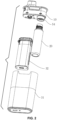
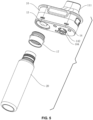
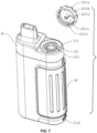
- the atomizing body and the battery assembly are detachably connected (as shown in FIGS. 4 and 6 ), or fixedly connected to constitute the electronic cigarette (as shown in FIGS. 7 and 9 ).
- an electronic cigarette comprises a first shell 11, a base 14, an e-liquid cartridge 20, a threaded connector 17, an e-liquid guide portion 52, a driving member 121, a sealing member 13, an elastic member 122, and a sealing plug 15.
- the driving member 121 comprises a hand-push section 1211 and a push rod 1212.
- the e-liquid chamber 51 is defined by the first shell 11 and the base 14.
- the bottom part of the base 14 comprises a hole 143 used to receive the bottom part of the atomizing core 16 to form a heating chamber.
- the sealing plug 15 is disposed on the base 14 and within the first shell to secure the atomizing core 16 in the e-liquid chamber 51, thereby preventing the e-liquid leakage.
- the base 14 comprises a first through-hole 141, and the sealing plug 15 comprises a second through-hole 151.
- the first through-hole 141 is connected to the second through-hole 151 to constitute the e-liquid guide portion 52.
- the threaded connector 17 is disposed around the first through-hole 141 and connected to the e-liquid cartridge 20.
- the base 14 further comprises a protrusion that is hollow and extends outward alongside the first through-hole 141.
- the threaded connector 17 is disposed within the protrusion 54.
- the e-liquid cartridge 20 is threaded onto the threaded connector 17 to direct the e-liquid through the e-liquid guide portion 52, the e-liquid chamber 51, and into the heating chamber.
- the sealing member 13 is disposed at the first through-hole 141. Specifically, the sealing member 13 is disposed on the side of the base 14 that is oriented towards the e-liquid cartridge 20 and securely fits with the base 14 using an interference fit.
- the hand-push section 1211 comprises a press-type cover disposed on the outside of the first shell 11.
- the push rod 1212 is disposed between the sealing member 13 and the hand-push section 1211.
- the press-type cover, the push rod 1212, and the sealing member 13 are arranged in a vertical manner.
- the press-type cover comprises a main body 1211a and a sidewall 1211b protruding along the edge of the main body 1211a.
- the first shell 11 further comprises a recess inside, with a protruding element 112 formed within the recess.
- An annular groove 113 is formed between the outer edge of the recess and the protruding element.
- the driving assembly 12 further comprises an elastic member 122 used to reset the sealing member 13.
- the elastic member 122 comprises a spring. One end of the spring abuts against the press-type cover, and the other end of the spring abuts within the annular groove 113.
- the spring functions to absorb and store external forces by utilizing its elastic deformation energy. Once the external forces diminish, the spring returns to its initial form and releases the stored energy, resulting in the press-type cover bouncing back from the annular groove 113. This mechanism facilitates the capability for repeated pressing.
- Example 2 shares the same characteristics as Example 1, except for specific variations shown in FIGS. 7-8 : the hand-push section comprises a press-type cover that needs to be rotated to a predefined position to active the pressing mechanism; and the structure of the first shell 11 is adjusted to accommodate the driving member 121.
- the inner side of the sidewall 1211b comprises four strip-like blocks 1211c protruding along the circumference of the sidewall 1211b and evenly distributed around the push rod 1212 at 90-degree intervals. Each end of the four strip-like blocks 1211c protrudes in the axial direction of the sidewall 1211b and away from the main body 1211a, forming a limited-stop protrusion 1211d. A gap 1211e is formed between every two adjacent strip-like blocks 1211c.
- the peripheral wall of the protruding element 112 comprises at least one ridge 1121 used to align with the corresponding gap. The at least one ridge 1121 fits the corresponding gap 1211e in width. The at least one ridge 1121 is slidable into the corresponding gap.
- Example 2 When sliding toward the one end of each of the four strip-like blocks 1211c, the at least one ridge 1121 is stopped by the adjacent limited-stop protrusions to align with the corresponding gap 1211e. In this configuration, at least one ridge 1121 is movable along the corresponding gap 1211e, allowing the press-type cover to be pressed down. Unlike Example 1, where direct pressing is used, Example 2 achieves a positioning function through rotation and pressing, effectively preventing inadvertent triggering due to collisions during movement.
- the protruding element 112 further comprises a circular recess (not shown in the figures); one end of the elastic member 122 (e.g., a spring) abuts against the main body of the press-type cover, and the other end of the elastic member 122 is disposed within the circular recess.
- the elastic member 122 e.g., a spring
- the angle of rotation and positioning is directly related to the number of the strip-like blocks.
- a 180-degree rotation achieves pressing
- a 120-degree rotation achieves pressing
- Example 2 The other structures of the electronic cigarette in Example 2 are similar to those in Example 1 and are not described herein.
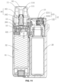
- Example 3 shares the same characteristics as Examples 1 and 2, except for specific variations shown in FIGS. 11-12 : the driving assembly 12 is laterally disposed within the e-liquid guide portion 52, and the sealing member 13 is disposed inside the atomizing body 10.
- the driving member 121 comprises a hand-push section 1211 and a push rod 1212.
- the hand-push section 1211 comprises a sliding button.
- the first shell comprises a guide groove disposed corresponding to the sliding button.
- the main body of the hand-push section 1211 is disposed on the outside of the first shell 11 and comprises a connecting part rigidly connected to the push rod 1212.
- the sealing member 13 is disposed inside the first shell 11 and connected to the push rod 1212.
- the sealing member 13 and the push rod 1212 are arranged laterally.
- One end of the elastic member 122 abuts against the sealing member 13, and the other end of the elastic member 122 abuts against the inner wall of the first shell 11.
- the sealing member 13 rebounds to its position of sealing the e-liquid guide portion 52 under the action of the elastic member 122.
- the sealing member 13 is shown not sealing the e-liquid guide portion 52
- the sealing member 13 is shown sealing the e-liquid guide portion 52.
- Example 3 The other structures of the electronic cigarette in Example 3 are similar to those in Examples 1-2 and are not described herein.
- the atomizing body 10 is detachably disposed within the third chamber 313.
- One end of the battery cell 32, oriented towards the third chamber 313, comprises a second conductive electrode 321.
- the atomizing body 10 is disconnected from the third chamber 313.
- the e-liquid cartridge 20 is unscrewed from the threaded connector 17 and replaced with a new e-liquid cartridge. Then, the atomizing body 10 is put back into position within the third chamber 313.
- the first shell 11 and the second shell 31 are fixedly connected or integrally formed.
- one end of the first chamber 311 is disposed away from the atomizing body 10 and comprises a first opening 3111.
- the electronic cigarette further comprises a sealing cap 3112 disposed on the first opening 3111 and used to open or close the first chamber 311.
- One end of the e-liquid cartridge 20 is disposed towards the first opening 3111 and comprises a knob switch 21 used for detaching and attaching the e-liquid cartridge 20 from the first opening 3111.
- the knob switch 21 is in the shape of the letter "I" or "X".
- the features facilitates the users in gripping the knob switch 21 firmly with their fingers at the bottom part of the e-liquid cartridge 20 and rotating the knob switch 21 to detach the atomizing body 10 from the e-liquid cartridge 20.
- the users open the sealing cap 3112, rotate the bottom part of the e-liquid cartridge 20, and detach the e-liquid cartridge 20 from the second opening 3113.
- This design ensures structural integrity while the convenience of an integrated shell design aids cost-effective manufacturing.
Landscapes
- Catching Or Destruction (AREA)
- Containers And Packaging Bodies Having A Special Means To Remove Contents (AREA)
- Disinfection, Sterilisation Or Deodorisation Of Air (AREA)
Applications Claiming Priority (2)
| Application Number | Priority Date | Filing Date | Title |
|---|---|---|---|
| CN202321445081.7U CN221711209U (zh) | 2023-06-07 | 2023-06-07 | 一种油瓶可换式电子烟 |
| CN202310674998.2A CN116725243A (zh) | 2023-06-07 | 2023-06-07 | 一种油瓶可更换式电子烟 |
Publications (1)
| Publication Number | Publication Date |
|---|---|
| EP4473853A1 true EP4473853A1 (de) | 2024-12-11 |
Family
ID=87762702
Family Applications (1)
| Application Number | Title | Priority Date | Filing Date |
|---|---|---|---|
| EP23192917.5A Pending EP4473853A1 (de) | 2023-06-07 | 2023-08-23 | Elektronische zigarette mit auswechselbarer e-flüssigkeitskartusche |
Country Status (3)
| Country | Link |
|---|---|
| US (1) | US20240407435A1 (de) |
| EP (1) | EP4473853A1 (de) |
| WO (1) | WO2024250523A1 (de) |
Citations (6)
| Publication number | Priority date | Publication date | Assignee | Title |
|---|---|---|---|---|
| US20170360095A1 (en) * | 2014-12-15 | 2017-12-21 | Philip Morris Products S.A. | Aerosol-generating system comprising moveable cartridge |
| WO2018024004A1 (zh) * | 2016-08-04 | 2018-02-08 | 湖南中烟工业有限责任公司 | 一种一次性烟弹、雾化器及电子烟 |
| WO2018114261A1 (en) * | 2016-12-19 | 2018-06-28 | Philip Morris Products S.A. | An aerosol-generating system having a cartridge and a bypass air inlet |
| CN217547277U (zh) | 2022-03-29 | 2022-10-11 | 深圳市希格莱特科技有限公司 | 一种新型一次性电子烟 |
| CN218527717U (zh) | 2022-11-02 | 2023-02-28 | 深圳市肯瑞特科技有限公司 | 按压调整式电子烟 |
| EP4374717A1 (de) | 2022-11-25 | 2024-05-29 | Tuanfang Liu | Elektronische zigarette |
Family Cites Families (9)
| Publication number | Priority date | Publication date | Assignee | Title |
|---|---|---|---|---|
| CN106455698B (zh) * | 2014-05-23 | 2020-01-10 | 吉瑞高新科技股份有限公司 | 电子烟 |
| WO2016112533A1 (zh) * | 2015-01-16 | 2016-07-21 | 惠州市吉瑞科技有限公司 | 雾化器、电子烟及用于防止电子烟烟油渗漏的加油方法 |
| CN207236084U (zh) * | 2016-09-02 | 2018-04-17 | 深圳市合元科技有限公司 | 可添加烟油的雾化器及电子烟 |
| WO2018094564A1 (zh) * | 2016-11-22 | 2018-05-31 | 常州聚为智能科技有限公司 | 储液组件、雾化器及其电子烟 |
| KR200493437Y1 (ko) * | 2017-12-25 | 2021-03-29 | 상하이 뉴 토바코 프로덕트 리서치 인스티튜트 컴퍼니 리미티드 | 에어로졸 발생 장치 및 전자 담배 |
| CN109275961B (zh) * | 2018-11-06 | 2023-11-24 | 深圳市优维尔科技有限公司 | 自吸式雾化器装置 |
| CN209965243U (zh) * | 2019-05-06 | 2020-01-21 | 深圳市益中源科技有限公司 | 一种电子烟油瓶组件、油气分离两段式雾化器及电子烟 |
| CN217722682U (zh) * | 2022-03-28 | 2022-11-04 | 深圳易佳特科技有限公司 | 一种雾化器及电子烟 |
| CN116725243A (zh) * | 2023-06-07 | 2023-09-12 | 深圳易佳特科技有限公司 | 一种油瓶可更换式电子烟 |
-
2023
- 2023-08-23 EP EP23192917.5A patent/EP4473853A1/de active Pending
- 2023-08-31 US US18/241,226 patent/US20240407435A1/en active Pending
- 2023-10-26 WO PCT/CN2023/126871 patent/WO2024250523A1/zh not_active Ceased
Patent Citations (6)
| Publication number | Priority date | Publication date | Assignee | Title |
|---|---|---|---|---|
| US20170360095A1 (en) * | 2014-12-15 | 2017-12-21 | Philip Morris Products S.A. | Aerosol-generating system comprising moveable cartridge |
| WO2018024004A1 (zh) * | 2016-08-04 | 2018-02-08 | 湖南中烟工业有限责任公司 | 一种一次性烟弹、雾化器及电子烟 |
| WO2018114261A1 (en) * | 2016-12-19 | 2018-06-28 | Philip Morris Products S.A. | An aerosol-generating system having a cartridge and a bypass air inlet |
| CN217547277U (zh) | 2022-03-29 | 2022-10-11 | 深圳市希格莱特科技有限公司 | 一种新型一次性电子烟 |
| CN218527717U (zh) | 2022-11-02 | 2023-02-28 | 深圳市肯瑞特科技有限公司 | 按压调整式电子烟 |
| EP4374717A1 (de) | 2022-11-25 | 2024-05-29 | Tuanfang Liu | Elektronische zigarette |
Also Published As
| Publication number | Publication date |
|---|---|
| WO2024250523A1 (zh) | 2024-12-12 |
| US20240407435A1 (en) | 2024-12-12 |
Similar Documents
| Publication | Publication Date | Title |
|---|---|---|
| RU2655290C1 (ru) | Распылитель, электронная сигарета и заменяемое устройство для хранения жидкости | |
| US20250056680A1 (en) | Reservoir filling system for an electronic vaping device | |
| EP3192382B1 (de) | Verdampfer und elektronische zigarette | |
| EP1289775B1 (de) | Flüssigkeitsapplikator | |
| CN205953490U (zh) | 分配器、贮存器、在二者之间传输液体的系统、及联接组件 | |
| EP3272240B1 (de) | Zerstäuber und elektronische zigarette damit | |
| EP3213650B1 (de) | Elektronische zigarette | |
| EP2949226B1 (de) | Elektronische zigarette | |
| CN207285188U (zh) | 一种电子烟 | |
| CN206525546U (zh) | 雾化组件和电子烟 | |
| CN116725243A (zh) | 一种油瓶可更换式电子烟 | |
| US20190216134A1 (en) | Syringe refiller for an electronic smoking device | |
| CN103002938A (zh) | 气雾发生器 | |
| KR20190014519A (ko) | 에어로졸 송달 장치용 에어로졸 전구체 조성물 혼합 시스템 | |
| JP2019524091A (ja) | 保管ケース | |
| CN112137180B (zh) | 雾化仓和雾化器 | |
| EP4473853A1 (de) | Elektronische zigarette mit auswechselbarer e-flüssigkeitskartusche | |
| CN221711209U (zh) | 一种油瓶可换式电子烟 | |
| CN223415716U (zh) | 电子雾化装置 | |
| CN216293060U (zh) | 气溶胶发生装置及其雾化组件 | |
| KR101654175B1 (ko) | 외부 케이싱이 교체 가능한 전자담배용 충전식 배터리 | |
| CN220756568U (zh) | 一种内置注油的电子烟 |
Legal Events
| Date | Code | Title | Description |
|---|---|---|---|
| PUAI | Public reference made under article 153(3) epc to a published international application that has entered the european phase |
Free format text: ORIGINAL CODE: 0009012 |
|
| STAA | Information on the status of an ep patent application or granted ep patent |
Free format text: STATUS: THE APPLICATION HAS BEEN PUBLISHED |
|
| AK | Designated contracting states |
Kind code of ref document: A1 Designated state(s): AL AT BE BG CH CY CZ DE DK EE ES FI FR GB GR HR HU IE IS IT LI LT LU LV MC ME MK MT NL NO PL PT RO RS SE SI SK SM TR |
|
| TPAC | Observations filed by third parties |
Free format text: ORIGINAL CODE: EPIDOSNTIPA |
|
| STAA | Information on the status of an ep patent application or granted ep patent |
Free format text: STATUS: REQUEST FOR EXAMINATION WAS MADE |
|
| 17P | Request for examination filed |
Effective date: 20250523 |
|
| STAA | Information on the status of an ep patent application or granted ep patent |
Free format text: STATUS: EXAMINATION IS IN PROGRESS |