EP4473945A1 - Plateau tibial ayant une structure de tige de plateau tibial et une articulation artificielle du genou - Google Patents
Plateau tibial ayant une structure de tige de plateau tibial et une articulation artificielle du genou Download PDFInfo
- Publication number
- EP4473945A1 EP4473945A1 EP23178474.5A EP23178474A EP4473945A1 EP 4473945 A1 EP4473945 A1 EP 4473945A1 EP 23178474 A EP23178474 A EP 23178474A EP 4473945 A1 EP4473945 A1 EP 4473945A1
- Authority
- EP
- European Patent Office
- Prior art keywords
- tibial tray
- anterior
- tibial
- posterior
- elements
- Prior art date
- Legal status (The legal status is an assumption and is not a legal conclusion. Google has not performed a legal analysis and makes no representation as to the accuracy of the status listed.)
- Withdrawn
Links
Images









Classifications
-
- A—HUMAN NECESSITIES
- A61—MEDICAL OR VETERINARY SCIENCE; HYGIENE
- A61F—FILTERS IMPLANTABLE INTO BLOOD VESSELS; PROSTHESES; DEVICES PROVIDING PATENCY TO, OR PREVENTING COLLAPSING OF, TUBULAR STRUCTURES OF THE BODY, e.g. STENTS; ORTHOPAEDIC, NURSING OR CONTRACEPTIVE DEVICES; FOMENTATION; TREATMENT OR PROTECTION OF EYES OR EARS; BANDAGES, DRESSINGS OR ABSORBENT PADS; FIRST-AID KITS
- A61F2/00—Filters implantable into blood vessels; Prostheses, i.e. artificial substitutes or replacements for parts of the body; Appliances for connecting them with the body; Devices providing patency to, or preventing collapsing of, tubular structures of the body, e.g. stents
- A61F2/02—Prostheses implantable into the body
- A61F2/30—Joints
- A61F2/38—Joints for elbows or knees
- A61F2/389—Tibial components
-
- A—HUMAN NECESSITIES
- A61—MEDICAL OR VETERINARY SCIENCE; HYGIENE
- A61F—FILTERS IMPLANTABLE INTO BLOOD VESSELS; PROSTHESES; DEVICES PROVIDING PATENCY TO, OR PREVENTING COLLAPSING OF, TUBULAR STRUCTURES OF THE BODY, e.g. STENTS; ORTHOPAEDIC, NURSING OR CONTRACEPTIVE DEVICES; FOMENTATION; TREATMENT OR PROTECTION OF EYES OR EARS; BANDAGES, DRESSINGS OR ABSORBENT PADS; FIRST-AID KITS
- A61F2/00—Filters implantable into blood vessels; Prostheses, i.e. artificial substitutes or replacements for parts of the body; Appliances for connecting them with the body; Devices providing patency to, or preventing collapsing of, tubular structures of the body, e.g. stents
- A61F2/02—Prostheses implantable into the body
- A61F2/30—Joints
- A61F2/30767—Special external or bone-contacting surface, e.g. coating for improving bone ingrowth
- A61F2/30771—Special external or bone-contacting surface, e.g. coating for improving bone ingrowth applied in original prostheses, e.g. holes or grooves
-
- A—HUMAN NECESSITIES
- A61—MEDICAL OR VETERINARY SCIENCE; HYGIENE
- A61F—FILTERS IMPLANTABLE INTO BLOOD VESSELS; PROSTHESES; DEVICES PROVIDING PATENCY TO, OR PREVENTING COLLAPSING OF, TUBULAR STRUCTURES OF THE BODY, e.g. STENTS; ORTHOPAEDIC, NURSING OR CONTRACEPTIVE DEVICES; FOMENTATION; TREATMENT OR PROTECTION OF EYES OR EARS; BANDAGES, DRESSINGS OR ABSORBENT PADS; FIRST-AID KITS
- A61F2/00—Filters implantable into blood vessels; Prostheses, i.e. artificial substitutes or replacements for parts of the body; Appliances for connecting them with the body; Devices providing patency to, or preventing collapsing of, tubular structures of the body, e.g. stents
- A61F2/02—Prostheses implantable into the body
- A61F2/30—Joints
- A61F2002/30001—Additional features of subject-matter classified in A61F2/28, A61F2/30 and subgroups thereof
- A61F2002/30108—Shapes
- A61F2002/3011—Cross-sections or two-dimensional shapes
- A61F2002/30159—Concave polygonal shapes
- A61F2002/30172—T-shaped
-
- A—HUMAN NECESSITIES
- A61—MEDICAL OR VETERINARY SCIENCE; HYGIENE
- A61F—FILTERS IMPLANTABLE INTO BLOOD VESSELS; PROSTHESES; DEVICES PROVIDING PATENCY TO, OR PREVENTING COLLAPSING OF, TUBULAR STRUCTURES OF THE BODY, e.g. STENTS; ORTHOPAEDIC, NURSING OR CONTRACEPTIVE DEVICES; FOMENTATION; TREATMENT OR PROTECTION OF EYES OR EARS; BANDAGES, DRESSINGS OR ABSORBENT PADS; FIRST-AID KITS
- A61F2/00—Filters implantable into blood vessels; Prostheses, i.e. artificial substitutes or replacements for parts of the body; Appliances for connecting them with the body; Devices providing patency to, or preventing collapsing of, tubular structures of the body, e.g. stents
- A61F2/02—Prostheses implantable into the body
- A61F2/30—Joints
- A61F2002/30001—Additional features of subject-matter classified in A61F2/28, A61F2/30 and subgroups thereof
- A61F2002/30108—Shapes
- A61F2002/3011—Cross-sections or two-dimensional shapes
- A61F2002/30159—Concave polygonal shapes
- A61F2002/30179—X-shaped
-
- A—HUMAN NECESSITIES
- A61—MEDICAL OR VETERINARY SCIENCE; HYGIENE
- A61F—FILTERS IMPLANTABLE INTO BLOOD VESSELS; PROSTHESES; DEVICES PROVIDING PATENCY TO, OR PREVENTING COLLAPSING OF, TUBULAR STRUCTURES OF THE BODY, e.g. STENTS; ORTHOPAEDIC, NURSING OR CONTRACEPTIVE DEVICES; FOMENTATION; TREATMENT OR PROTECTION OF EYES OR EARS; BANDAGES, DRESSINGS OR ABSORBENT PADS; FIRST-AID KITS
- A61F2/00—Filters implantable into blood vessels; Prostheses, i.e. artificial substitutes or replacements for parts of the body; Appliances for connecting them with the body; Devices providing patency to, or preventing collapsing of, tubular structures of the body, e.g. stents
- A61F2/02—Prostheses implantable into the body
- A61F2/30—Joints
- A61F2002/30001—Additional features of subject-matter classified in A61F2/28, A61F2/30 and subgroups thereof
- A61F2002/30108—Shapes
- A61F2002/3011—Cross-sections or two-dimensional shapes
- A61F2002/30159—Concave polygonal shapes
- A61F2002/30181—Y-shaped
-
- A—HUMAN NECESSITIES
- A61—MEDICAL OR VETERINARY SCIENCE; HYGIENE
- A61F—FILTERS IMPLANTABLE INTO BLOOD VESSELS; PROSTHESES; DEVICES PROVIDING PATENCY TO, OR PREVENTING COLLAPSING OF, TUBULAR STRUCTURES OF THE BODY, e.g. STENTS; ORTHOPAEDIC, NURSING OR CONTRACEPTIVE DEVICES; FOMENTATION; TREATMENT OR PROTECTION OF EYES OR EARS; BANDAGES, DRESSINGS OR ABSORBENT PADS; FIRST-AID KITS
- A61F2/00—Filters implantable into blood vessels; Prostheses, i.e. artificial substitutes or replacements for parts of the body; Appliances for connecting them with the body; Devices providing patency to, or preventing collapsing of, tubular structures of the body, e.g. stents
- A61F2/02—Prostheses implantable into the body
- A61F2/30—Joints
- A61F2/30767—Special external or bone-contacting surface, e.g. coating for improving bone ingrowth
- A61F2/30771—Special external or bone-contacting surface, e.g. coating for improving bone ingrowth applied in original prostheses, e.g. holes or grooves
- A61F2002/3082—Grooves
-
- A—HUMAN NECESSITIES
- A61—MEDICAL OR VETERINARY SCIENCE; HYGIENE
- A61F—FILTERS IMPLANTABLE INTO BLOOD VESSELS; PROSTHESES; DEVICES PROVIDING PATENCY TO, OR PREVENTING COLLAPSING OF, TUBULAR STRUCTURES OF THE BODY, e.g. STENTS; ORTHOPAEDIC, NURSING OR CONTRACEPTIVE DEVICES; FOMENTATION; TREATMENT OR PROTECTION OF EYES OR EARS; BANDAGES, DRESSINGS OR ABSORBENT PADS; FIRST-AID KITS
- A61F2/00—Filters implantable into blood vessels; Prostheses, i.e. artificial substitutes or replacements for parts of the body; Appliances for connecting them with the body; Devices providing patency to, or preventing collapsing of, tubular structures of the body, e.g. stents
- A61F2/02—Prostheses implantable into the body
- A61F2/30—Joints
- A61F2/30767—Special external or bone-contacting surface, e.g. coating for improving bone ingrowth
- A61F2/30771—Special external or bone-contacting surface, e.g. coating for improving bone ingrowth applied in original prostheses, e.g. holes or grooves
- A61F2002/30878—Special external or bone-contacting surface, e.g. coating for improving bone ingrowth applied in original prostheses, e.g. holes or grooves with non-sharp protrusions, for instance contacting the bone for anchoring, e.g. keels, pegs, pins, posts, shanks, stems, struts
-
- A—HUMAN NECESSITIES
- A61—MEDICAL OR VETERINARY SCIENCE; HYGIENE
- A61F—FILTERS IMPLANTABLE INTO BLOOD VESSELS; PROSTHESES; DEVICES PROVIDING PATENCY TO, OR PREVENTING COLLAPSING OF, TUBULAR STRUCTURES OF THE BODY, e.g. STENTS; ORTHOPAEDIC, NURSING OR CONTRACEPTIVE DEVICES; FOMENTATION; TREATMENT OR PROTECTION OF EYES OR EARS; BANDAGES, DRESSINGS OR ABSORBENT PADS; FIRST-AID KITS
- A61F2/00—Filters implantable into blood vessels; Prostheses, i.e. artificial substitutes or replacements for parts of the body; Appliances for connecting them with the body; Devices providing patency to, or preventing collapsing of, tubular structures of the body, e.g. stents
- A61F2/02—Prostheses implantable into the body
- A61F2/30—Joints
- A61F2/30767—Special external or bone-contacting surface, e.g. coating for improving bone ingrowth
- A61F2/30771—Special external or bone-contacting surface, e.g. coating for improving bone ingrowth applied in original prostheses, e.g. holes or grooves
- A61F2002/30878—Special external or bone-contacting surface, e.g. coating for improving bone ingrowth applied in original prostheses, e.g. holes or grooves with non-sharp protrusions, for instance contacting the bone for anchoring, e.g. keels, pegs, pins, posts, shanks, stems, struts
- A61F2002/30884—Fins or wings, e.g. longitudinal wings for preventing rotation within the bone cavity
-
- A—HUMAN NECESSITIES
- A61—MEDICAL OR VETERINARY SCIENCE; HYGIENE
- A61F—FILTERS IMPLANTABLE INTO BLOOD VESSELS; PROSTHESES; DEVICES PROVIDING PATENCY TO, OR PREVENTING COLLAPSING OF, TUBULAR STRUCTURES OF THE BODY, e.g. STENTS; ORTHOPAEDIC, NURSING OR CONTRACEPTIVE DEVICES; FOMENTATION; TREATMENT OR PROTECTION OF EYES OR EARS; BANDAGES, DRESSINGS OR ABSORBENT PADS; FIRST-AID KITS
- A61F2/00—Filters implantable into blood vessels; Prostheses, i.e. artificial substitutes or replacements for parts of the body; Appliances for connecting them with the body; Devices providing patency to, or preventing collapsing of, tubular structures of the body, e.g. stents
- A61F2/02—Prostheses implantable into the body
- A61F2/30—Joints
- A61F2/46—Special tools for implanting artificial joints
- A61F2002/4631—Special tools for implanting artificial joints the prosthesis being specially adapted for being cemented
Definitions
- the invention relates to a tibial shaft with shaft structure having the features of claim 1 and an artificial knee joint with the features of claim 27.
- Joint replacements in particular artificial knee joint replacements, have been known for quite some time.
- a tibial tray part is connected with the proximal end of the tibia of the patient. The connection is made through the distal part of the tibial tray, i.e. the tibial tray shaft.
- a femoral part is connected with the distal end of the femur of the patient.
- a tibial insert is connected with the proximal surface of the tibial tray so that after the completion of the surgical procedure, the tibial insert is positioned between the distal surface of the femoral part and the proximal surface of the distal tray.
- a tibial tray and a tibial insert of this kind are e.g. described in EP 3 626 209 B1 .
- the tibial tray with the features of claim 1 addresses these issues.
- the tibial tray comprises a distal surface, wherein a tibial tray shaft structure extends away from the distal surface in the distal direction.
- the tibial tray structure forms a protrusion, which is inserted into the tibial bone.
- the tibial tray structure comprises at least three shaft wall elements which are so arranged relative to each other that the cross-sections of the at least three shaft wall elements in a plane perpendicular to the distal direction are T-shaped, Y-shaped or X-shaped.
- T-shaped structure comprises three shaft wall elements, two forming the bar of the T, one forming the stem. The bar and the stem are positioned under an angle of 90°.
- a Y-shaped structure also comprises three shaft wall elements, but three angles can be different from 90°.
- the shaft wall elements are spaced equally apart by 120°.
- two shaft wall elements can be spaced apart by 90°, the remaining third shaft wall element is then spaced apart from the others by 135° each.
- An X-shaped structure comprises four shaft wall elements.
- the shaft wall elements are positioned around a central axis, with angles between the shaft wall elements. It is possible, that e.g. each of the two angle sets between the shaft wall elements comprises angles of the same size (e.g. two angles of 110° each, and two angles of 70° each).
- the area of the cross-sections decreases strictly monotonously from the distal surface in the distal direction.
- the tibial tray structure generally tapers from a broad base into the distal direction. This facilitates an effective insertion of the tibial tray into the tibia.
- the tapering is continuous with sections parallel to the distal surface.
- outer rims of the at least three shaft wall elements converge strictly monotonously in the distal direction and towards an axis of the tibial tray structure. Again, this is a further aspect of tapering, facilitating an effective insertion of the tibial tray into the tibia.
- the shape of the outer rim could, e.g., be curved with a uniform direction of curvature (e.g. an exponential shape). But the outer rims of the least three shaft wall elements have in one embodiment at least one inflection point, in particular three inflection points. This means that the direction of the curvature - not only the amount - changes at least once.
- the curvature of the outer rim should not change too rapidly, so that any change of a tangent angle at an outer rim of the at least three shaft wall elements should be less than 30° over a 10% change in the distal direction, in particular any tangent angle of the outer rim of the at least three shaft wall elements within a third of the height of the tibial tray structure measured from the distal surface.
- the changes in the slope should be smaller in the third of the tibial shaft structure closest to the distal surface.
- At least 50% of the volume of the tibial tray structure is located within a third of the height of the tibial tray structure measured from the distal surface.
- At least one of the shaft wall elements can have a wall thickness between 1 and 6 mm, in particular 2 to 5 mm, for ceramic materials 1 and 5 mm, measured at the point farthest way from the axis and on the distal surface.
- the radius at the transition from the outer rim of at least one of the at least three shaft wall elements to the sidewalls of the at least one of the at least three shaft wall element is in the range of 0,5 to 4 mm.
- At least one of the at least three shaft wall elements comprise at least one cement holding structure, in particular at least one recess structure for retaining bone cement.
- Those cement holding structures can be preferably positioned on the anterior and / or posterior side close to the tibial tray.
- the transition point from the outer rim into the tibial shaft structure in the distal surface is located at least 5 mm from the lateral sides and / or the posterior side of the distal surface. This ensures a suitable distance from the edge of the distal surface and makes sure that the tibial shaft structure is positioned within the substantia spongiosa and outside the substantia corticalis. The distance is measured from the end of the outer rim in a straight line to the edge of the distal surface.
- the tibial tray structure comprises a surface extending between at least two of the outer rims of the at least three shaft wall elements or between two side walls of the at least three shaft wall elements.
- the radius at the transition from the distal surface to at least one of the at least three shaft wall elements and / or the smooth surface can be in the range of 1 to 4 mm.
- the axis of the tibial tray shaft structure is located on the distal surface at one third of the distance between the anterior rim to the posterior rim, measured from the anterior rim. This means that the axis of the tibial tray shaft is located somewhat more to the anterior side than the posterior side.
- the axis of the tibial tray shaft is defined for X, Y, and T shaped tibial tray shaft structures, as the at least three shaft wall elements are converging towards this axis strictly monotonously.
- the distance of the axis of the tibial tray shaft structure is 5 mm, 5,67 mm, 6,33 mm or 7 mm from the center of the distal surface.
- embodiments can have tibial shaft tray structures with a height from the distal surface of 35 mm, 40 mm, 45 mm, or 55 mm.
- the thickness of the shaft wall elements can be 3 mm, 3,75 mm, 4,25 mm or 5 mm.
- the angle between the shaft wall elements is between 90° and 180° on the anterior side and between 30° to 120° on the posterior side.
- a T-shaped tibial tray structure with three shaft wall elements would have an anterior angle of 180° and two 90° angles on the posterior side.
- the shapes of X- and Y-shaped tibial tray structure could vary within in the stated regions.
- the tibial tray shaft structure comprises at least one cement holding structure, in particular a hole, a groove and / or a recess without any undercut. This allows an efficient entering of cement in the cement holdings structures.
- the at least one cement holding structure is located within the vertical two thirds of the tibial tray shaft structure measured from the distal surface in the distal direction, in particular within the first third. This means that the at least one cement holding structure is preferably located towards the distal surface and not towards the distal end of the tibial tray shaft structure.
- the tibial tray comprises least one anterior fixation element, in particular exactly one anterior fixation element, which is positioned at the anterior side of the proximal surface, the posterior side of the at least one anterior fixation element comprising a wall which in a plane parallel to the proximal surface is perpendicular to the medial plane of the proximal surface.
- the at least one anterior fixation element comprises at least one form-fitting element, in particular, at least one cavity in the posterior wall of the at least one anterior fixation element and / or at least one channel through the at least one anterior fixation element, for a corresponding form-fitting element of the tibial insert, the at least one form-fitting element of the at least one anterior fixation element being in particular positioned in a region in which the load transfer is at less than 70%, in particular 50% from the maximum load transfer.
- the at least one anterior fixation element can comprise at least on guiding surface for a tibial insert, in particular the guiding surface having a curved and / or a plane part, in a proximal direction of the at least form-fitting element.
- a protrusion of the tibial insert contacts the guiding surface and glides along the guiding surface so that its movement during the fitting is guided and the protrusions can snap into the at least one form-fitting element.
- the at least one guiding surface comprises a plane part or is a plane which is inclined relative to the horizontal plane by an angle in the range between 5 to 45°, in particular 30°.
- the tibial tray comprises a proximal surface, the proximal surface comprising at least two, in particular exactly two central fixation elements for enabling a connection with the tibial insert as a further part of an artificial knee joint, wherein the at least two central fixation elements are protrusions from the proximal surface in the proximal direction and the at least two central fixation elements are positioned symmetrically and / or parallel to a medial plane of the proximal surface, the medial plane being perpendicular to the proximal surface and intersecting the proximal surface in the middle between two most lateral points of the proximal surface.
- the at least two central fixation elements are symmetrically positioned relative to a frontal plane perpendicular to the medial plane, the frontal plane in particular going through the most lateral points of the proximal surface.
- the at least two central fixation elements can comprise a central fixation element recess for providing a better fit with the tibia insert.
- the at least two, or exactly two central fixation elements can be constructed as form-fitting and / or press-fitting elements.
- an embodiment of the tibial tray comprises at least one, in particular exactly one, posterior fixation element, positioned symmetrically to the medial plane of the proximal surface comprising a posterior wall flush with the posterior rim of the tibial tray and / or comprising an anterior wall which is essentially positioned parallel to the posterior wall of the at least one anterior fixation element.
- the sidewalls and / or the anterior wall of the of the at least one posterior element can in particular be tilted by an angle between 0 and 45°, in particular between 0 and 30°, more particular by an angle of 10°, relative to a plane which is perpendicular to the proximal plane and / or the sidewalls and the anterior wall of the of the at least one posterior element comprise an undercut.
- This enables e.g. the formation of a posterior block with inward tilted sidewalls (i.e. sidewalls with an angle greater than 0°) and sidewalls converging to the anterior side or a tongue and groove system (undercut).
- Such a posterior fixation element can be used as a fulcrum when attaching a tibial insert.
- the tibial tray can be manufactured completely or in part from ceramic, a polymer material or a metal.
- a tibial tray can comprise a proximal surface, the proximal surface comprising at least two, in particular exactly two, central fixation elements for enabling a connection with a tibial insert as a further part of artificial knee joint.
- the central fixation elements are protrusions from the proximal surface, which can be connected as form-fitting and / or force locking with the tibial insert.
- the at least two central fixation elements are designed as protrusions from the proximal surface in the proximal direction, i.e. the central fixation elements generally point away from the proximal surface in the direction of the tibial insert.
- the at least two central fixation elements are positioned symmetrically and / or parallel to a medial plane of the proximal surface, the medial plane being perpendicular to the proximal surface and intersecting the proximal surface in the middle between two most lateral points of the proximal surface.
- the medial plane is dividing the proximal surface into two lateral halves.
- the at least two central fixation elements are oriented symmetrically and / or parallel to the medial plane.
- the at least two fixation elements are oriented asymmetrically relative to the medial plane. This can imply different angles relative to the medial plane and / or different distances from the medial plane.
- the at least two central fixation elements are configured as cylindrical protrusions or linear protrusions, in particular designed for a press-fit and / or form-fit.
- Cylindrical means that the protrusion has e.g. a circular, elliptical cross-section.
- Linear means that the protrusion extends linearly on the proximal surface.
- At least one of the central fixation elements can e.g. have a linear or cylindrical shape.
- the at least two central fixation elements are symmetrically positioned relative to a frontal plane perpendicular to the medial plane.
- the frontal plane is dividing the proximal surface into an anterior and a posterior part. In particular, it is possible that the frontal plane is going through the most lateral points of the proximal surface.
- the posterior wall of the at least one anterior fixation element and / or the anterior wall of the at least one posterior fixation element can comprise an undercut.
- the height of the at least two central fixation elements, the at least one anterior fixation element and / or the at least one posterior fixation element extending from the proximal surface is in the range between 1 mm and 6 mm, in particular between 3 mm and 4 mm, 5 mm and / or wherein the anterior and / or posterior ends of the at least two central fixation elements are rounded.
- the height of the at least two central fixation elements, the height of the at least one anterior fixation element and / or the height of the at least one posterior fixation element above the proximal surface is constant or varies by maximally 10% from the minimal height.
- tibial insert designed or configured to match the tibial tray as claimed.
- the tibial insert can comprise one recess in the distal surface for the matching of at least one posterior fixation element, the recess comprising at least one stress relief notch at the junction of two walls of the recess. This prevents the build-up of mechanical stress sharp corners where two walls of the recess meet.
- the secure connection can be enabled by at least one form-fitting element of the tibial insert for engaging the at least one form-fitting element of the at least one anterior fixation element of the tibial tray.
- the connection can also be made with a press-fitting connection or a combination.
- an artificial knee joint comprising a claimed tibial tray and a claimed tibial insert, wherein there is a light press-fit connection between the tibial insert and the at least two central fixation elements, the at least one anterior fixation element and the at least one posterior fixation element, in particular having a press-fit in the range of 0 to 450 ⁇ m, in particular in the range of 0 to 250 ⁇ m.
- an artificial knee joint there is at least one press-fitting region between the posterior fixation element and the tibial insert, in particular created by an angular mismatch between two walls. This allows for an improved assembly of the joint and a reduction of micromovements in the posterior parts of the joint.
- an artificial ceramic knee joint 100 is shown in a perspective view from a posterior position.
- a femoral part 40, a tibial insert 30 and a tibial tray 20 of the metal-free artificial knee joint are shown.
- Alternative embodiments are not metal-free.
- the complete artificial art knee joint 100 is metal-free, e.g. a combination of ceramic and polymeric materials.
- the tibial tray 20 can, e.g., be made from ceramic and the tibial insert 30 can be made from a polymeric material.
- a femoral part 40 is shown with two condyles fitting into matching grooves in the proximal surface of a tibial insert 30 at the distal end of the femoral part 40.
- the tibial insert 30 is connected with a tibial tray 20, the distal surface D of the tibial insert 30 facing the proximal surface P of the tibial tray 20.
- a tibial tray 20 In connection with Fig. 2 to 8 , embodiments of a tibial tray 20 are described. In Fig. 9 to 14 , embodiments of a tibial tray 10 and a tibial insert 30 are described which can be used in connection within the embodiments of the tibial tray 20 described herein.
- a perspective view of the distal side of an embodiment of a tibial tray 20 is shown.
- the shape of the distal surface D is roughly shaped as the proximal side of the tibial tray 20 (see e.g. Fig 9 to 15 ).
- a tibial tray shaft structure 21 is located in the center of the distal surface D, i.e. in the middle of the lateral width between points L1 and L2.
- the tibial shaft structure 21 is essentially Y-shaped (i.e. is referring to a cross-section in a plane parallel to the distal surface D) with an axis A in the center.
- the tibial tray structure 21 comprises three shaft wall elements 22, 23, 24 that are placed around the axis A with angles of 120° between them.
- One shaft wall element 22 of the Y is oriented to the anterior side of the tibial tray 20, the two other shaft wall elements 23, 24 are oriented to the posterior side of the tibial tray 20.
- the tibial tray structure 21 extends away from the distal surface D into a distal direction DD (as indicated e.g. in Fig. 5 ) that in Fig. 2 is essentially pointing out of the plane of the figure.
- an elevated rim R is located, extending away from the distal surface D.
- the width in the plane parallel to the distal surface D is between 1 to 4 mm.
- the three shaft wall elements 22, 23, 24 of the tibial tray shaft structure 21 each comprise an outer rim 26.
- the outer rims 26 are thin faces of the shaft wall elements 22, 23, 24.
- the thickness T of the shaft wall elements 22, 23, 24 measured at the endpoints (i.e. the points farthest away from the axis A on the distal surface D) is between 2 and 5 mm.
- the outer rims 26 converge from their broad base at the distal surface D towards the axis A in the distal direction.
- the convergence is strictly monotonous, i.e. there is no section of the outer rims 26 being parallel to the distal surface D.
- the slope of the outer rims 26 is increasing from the base, i.e. the distal surface D, towards the axis.
- the change of the slope is smooth, without kinks.
- the outer rims 26 are connected by a smooth surface S, here an inward (i.e. towards the axis A) curved surface.
- the surface 13 itself has no kinks or edges to enable a good insertion into the tibia.
- the transition from the smooth surface 13 to the outer rim 26 is also smooth, i.e. without kinks or edges.
- the radius R2 of this transition is between 1 and 4 mm, in particular depending on the size of the tibial tray structure 21.
- the transition from the distal surface D into the shaft wall elements 22, 23, 24 and / or the smooth wall 13 is rounded with the radius R1 being in the range of 1 to 4 mm.
- the cross-sectional area of the tibial shaft structure 21 in a plane C parallel to the distal surface D is greatest at the base at the distal surface D.
- the cross-sectional area is getting smaller (in particular strictly monotonous smaller) as the tibial shaft structure 21 extends into the distal direction DD.
- the base plate with the distal surface D has a thickness in the range of 2 mm to 6 mm, in particular 4,5 mm.
- a tibial tray 20 which comprises four shaft wall elements 22, 23, 24, 25 in an X-shaped pattern. Two of the shaft wall elements 24, 25 are oriented towards the anterior side of the tibial tray 20, two of the shaft wall elements 22, 23 are oriented towards the posterior side.
- the geometry of the outer rims 26, the smooth surface 13 in the angled space between the shaft wall elements 22, 23, 24, 25 and in particular the convergence of the outer rims 26 in the distal direction D towards the axis A are analog to the embodiment shown in connection with Fig. 2 , so that reference to the description can be made.
- FIG. 4 in a perspective view is a further variation of the embodiment shown in Fig. 2 and 3 .
- the above given description is applicable as well.
- the tibial tray structure 21 has a T-shaped cross-section in a plane parallel to the distal surface D.
- the shaft wall elements 22, 24 forming the bar of the T are positioned essentially parallel to anterior side, one shaft wall element 25 forming the stem of the T is directed perpendicularly to the posterior side of the tibial tray 20.
- the three shaft wall elements 22, 23, 24 of the tibial tray structure 21 have cross-sectional areas, which converge strictly monotonously towards in the distal direction DD towards the axis A.
- the outer rims 22, 23, 24 have slopes (measured against the distal plane) which are always greater than 0°, i.e. the outer rims have no plateaus.
- the outer rims 26 have three inflection points 27 in which there is a change in curvature.
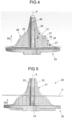
- Fig. 5 shows the embodiment of Fig. 4 in a rear view.
- a sectional plane C parallel to the distal surface D is shown.
- the sectional plane C separates the lower third of the tibial tray structure 21 from the upper two thirds.
- at least 50% of the volume of the shaft wall elements 22, 23, 24 are between this sectional plane C and the distal surface D, i.e. in the third closest to the distal surface D. This is also the case for the other embodiments shown in Fig. 2 and 3 .
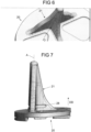
- Fig. 6 shows the same embodiment as the one shown in Fig. 4 and 5 , i.e. a tibial tray structure 21 with a T-structure.
- a tibial tray structure 21 with a T-structure i.e. a tibial tray structure 21 with a T-structure.
- the shape of the outer rim 26 and the rounded transitions from the distal surface into the tibial stray structure 21 which can be seen clearly in the figure.
- Fig. 7 basically shows the embodiment of Fig. 4 to 6 in a side view, so that the above description is applicable.
- this embodiment comprises one or more anterior and / or posterior cement holding structures, here recess structures 28 in the tibial tray structure 21.
- the recess structure 28 is shaped like a groove essentially parallel to the distal surface in this embodiment. Other shapes are possible in principle.
- cement holding structure 28 should be oriented in a way that the bone cement is not easily removed when implanting the tibial tray 20.
- a variant of the embodiment shown in Fig. 4 to 7 is depicted, i.e. a T-structure as a tibial tray structure 21.
- the distal surface D comprises a recess 14. Furthermore, it is indicated that transition point from the outer rim 26 of the tibial shaft structure 21 in the distal surface D is located at least 5 mm (D1) from the lateral sides and / or the posterior side of the distal surface D.
- the middle plane of the shaft wall elements 22, 23 are extended to the lateral sides / and or the posterior side of the distal surface D, defining the distances D1. This allows a good placement of the tibial tray structure 21 in the bone.
- tibial tray 20 and the tibial insert 30 are described, in particular features of the proximal surface P of the tibial tray 20 and the matching distal surface D of the tibial insert 30.
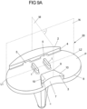
- Fig. 9 , 9A show a perspective view onto the proximal surface P of the tibial tray 20.
- the tibial tray is shown for reducing complexity without the reference numbers but with reference planes M, N which are used in the following to define the locations of features on the tibial tray 20.
- a medial plane M is perpendicular to the planar proximal surface P and intersecting the proximal surface P in the middle between to most lateral points L1, L2 of the proximal surface P.
- a frontal plane N is perpendicular to the medial plane M.
- the dimensions are grouped in different sizes. There are eight different sizes for the distance between the points L1 and L2. This is used to allow for artificial knee joints 100 for differently sized patients. The smallest distance between L1 and L2 is 60 mm. The other seven sizes have distances of 64 mm, 68 mm, 72 mm, 76 mm, 80 mm, 84 mm and 88 mm (i.e. using an increment of 4 mm). Other embodiments can use different absolute sizes and / or different increments, the increments do not have to be identical.
- the corresponding sizes are 38,7 mm, 41,3 mm, 43,9 mm, 46,5 mm, 49,0 mm, 51,6 mm, 54,2 mm and 56,8 mm.
- Other embodiments can use different absolute sizes and / or different increments, again, the increments do not have to be identical.
- the proximal surface P of the tibial tray 20 is structured so that a corresponding tibial insert 30 (see e.g., Fig. 1 , 13 ) can be securely fastened to the tibial tray 20 (see Fig. 12A, 12B ).
- the structures 1, 2, 3 on the planar proximal surface P provide a symmetric, flat plateau with island-like fixation elements 1, 2, 3 for the tibial insert 30 connection using a press-fit or interference-fit (see Fig. 11 ).
- the proximal surface P comprises two central fixation elements 1. As will be described below, those two central fixation elements enable a secure connection with the tibial insert (see Fig. 10B ) as a further part of the artificial knee joint 100.
- the two central fixation elements 1 are linear protrusions, protruding away from the proximal surface P in the proximal direction, so that they can match corresponding notches (or grooves) 34 in the tibial insert 30 (see Fig. 10B ).
- the central fixation elements 1 could have a cylindrical shape. Other shapes and different positions of the central fixation elements 1 will be shown below.
- the two central fixation elements 1 are positioned symmetrically and parallel to the medial plane M.
- the two central fixation elements 1 are still symmetric to the medial plane M, but not quite parallel as they are angled by less than 5° relative to the median plane M, so that the two linear fixation elements 1 show some convergence towards the anterior side.
- the two central fixation elements 1 are asymmetric to the median plane M but parallel to each other.
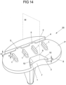
- FIG. 14 in a different embodiment, more than two central fixation elements 1 can be used. Otherwise, the embodiment of Fig. 14 is comparable to the one described in connection with Fig. 9 .
- the two central fixation elements 1 are symmetrically positioned relative to the frontal plane N perpendicular to the medial plane M.
- the frontal plane N is going through the most lateral points L1, L2 of the proximal surface P.
- the two central fixation elements 1 have the form of a parallelepiped, the anterior and the posterior ends of the central fixation elements 1 are rounded.
- the two central fixation elements 1 have a height H extending in the embodiment shown 3,8 mm from the proximal surface P of the tibial tray 20. In other artificial knee joints 100, the height H can be up to 6 mm. In the embodiment shown, the height H of the central fixation elements 1 is constant. In other embodiments, the height H can vary relative to the proximal surface P. In other embodiments, the height H of the at least two central fixation elements 1 over the proximal surface varies by maximal 10% from the minimal height.
- the distance between the two central fixation elements 1 is 10,5 mm as measured between the interior walls and 15,5 mm as measured between the exterior walls.
- the width of each of the central fixation elements is 2,5 mm.
- the distance between the central fixation elements is chosen here to be as large as possible to provide a large torque and to prevent a shearing off of polyethylene material from the tibial insert 30. If the distance between the two central fixation elements 1 is always the same, tibial inserts 30 of different sizes can be used in assembling the artificial knee joint 100.
- the orientation of the central fixation element 1 on the proximal surface P enables a linear guiding of the tibial insert 30 during the assembly (see Fig. 12A, 12B ), so that the central fixation elements 1 could also be termed as central guide rails. Furthermore, the central fixation elements 1 allow for an increased stability against shear forces in the artificial knee joint.
- the proximal surface P also comprises an anterior fixation element 2 that is located at the anterior rim of the proximal surface P.
- the posterior side of the anterior fixation element 2 comprises a posterior wall 4 that is positioned perpendicular to the medial plane M of the proximal surface P. Therefore, the posterior wall 4 is also essentially perpendicular to the two linear central fixation elements 1.
- the anterior fixation element 2 in this embodiment has the same height H as the central fixation element 1. In other embodiments the heights of the anterior fixation element 2 and the central fixation elements 1 can be different.
- the anterior fixation element 2 comprises two cavities 5, each in the form of a channel (i.e. the channel being open at both ends) with an essentially rectangular cross-section. As will be shown in connection with Fig. 12A, 12B , those cavities are form-fitting elements 5 cooperating with matching form-fitting elements 31 on the tibial insert 30.
- the form-fitting elements 5 in the anterior fixation element are positioned symmetrically relative to the medial plane M.
- the anterior fixation element 2 comprises only one or more than two form-fitting elements 5.
- the cross-section of the cavities of the form-fitting elements 5 does not have to be rectangular, as e.g. round or polygonal cross-sections can also be used.
- the anterior fixation element 2 is one continuous element at the anterior rim of the tibial tray 20.
- the anterior fixation element 2 can be divided into more than one part, e.g. two elements, each of them comprising a form-fitting element 5.
- the two form-fitting elements 5 in the anterior fixation element 2 are positioned in a region in which the mechanical load transfer is at less than 50% from the maximum load transfer. This is due to the fact that the channel-like form-fitting elements 5 somewhat weaken the structure of the anterior fixation element 1.
- a further structure on the proximal surface P is a posterior fixation element 3, which is positioned at the posterior rim of the proximal surface P.
- the posterior fixation element 3 is positioned symmetrically relative to the medial plane M and comprises a posterior wall 7 flush with the posterior rim 8 of the tibial tray 20.
- the posterior wall 7 is following the curved shape of the posterior rim 8 of the tibial tray 20.
- the cross-section of the anterior fixation element 3 in a plane parallel to the proximal surface P is symmetric to the medial plane M.
- the posterior fixation element 3 in this embodiment has the same height H as the central fixation element 1. In other embodiments the heights of the posterior fixation element 3 and the central fixation elements 1 can be different.
- the embodiment shown in Fig. 9 also comprises an anterior wall 9 of the posterior fixation element 3 and a posterior wall 4 of the anterior fixation element 2.
- the respective rims of those walls 4, 9 at the proximal surfaces of the posterior element 3 and the anterior fixation element 2 are parallel to each other. If the walls, 4, 9 would have no undercut (i.e. the walls 4, 9 are not tilted), the walls 4, 9 themselves would be parallel. Therefore, the two central fixation elements 1 are oriented perpendicular to both the posterior wall 4 of the anterior fixation element 2 and the anterior wall 9 of the posterior fixation element 3.
- the posterior fixation element 3 also comprises two sidewalls 10 that are angled relative to the anterior wall 9 of the posterior fixation element 3.
- the angle ⁇ between the two sidewalls 10 and the anterior wall 9 in a plane parallel to the proximal plane P is in the range between 0° and 22°, in particular in the range between 15° and 22°. Therefore, the two sidewalls 10 are oriented convergent in the anterior direction.
- the overall horizontal shape of the posterior fixation element 3 is roughly trapezoidal, with the long side of the trapezoid being curved.
- the two sidewalls 10 of the posterior fixation element 3 are tilted inwards to form an undercut by an angle between 1 and 45°, in particular between 20 and 30° relative to a plane which is perpendicular to the proximal plane P. Therefore, the top surface of the posterior fixation element 3 is slightly larger than the base cross-section in the plane of the proximal surface.
- the anterior wall 9 of the posterior fixation element 3 comprises an undercut 6, the undercut 6 forming an angle ⁇ between 1° and 45°, in particular 30° with a plane perpendicular to the proximal surface P.
- the undercut 6 can have - at least in parts - a curved shape.
- the posterior wall 4 of the anterior fixation element 2 comprises an undercut 6.
- the height H of the fixation elements 1, 2, 3 above the proximal surface P was identical. That does not have to be the case in all embodiments.
- the matching tibial tray 20 and tibial insert 30 are shown side by side in Fig. 10A, 10B .
- the embodiment of the tibial tray 20 in Fig. 10A is already described in Fig. 9 , so reference can be made to the respective description.
- the distal surface D of the tibial insert 30 is shown in Fig. 10B .
- the comparison of the two parts 20, 30 shows that the tibial insert 30 can be connected with the tibial tray 20 so that the first fixation elements 1 fit into matching notches 34 in the tibial insert 30.
- the tibial insert 30 comprises a recess 32 (see Fig. 10B ) in the distal surface D for the matching posterior fixation element 3 of the tibial tray 20.
- the recess 32 is open towards the posterior side so that it only has an anterior wall 35 and two sidewalls 36.
- the sidewalls 36 of the recess 32 are angled to match the angled sidewalls 10 of the posterior fixation element 3. In the corners where the anterior wall 35 and the two sidewalls 36 of the recess 32 meet, stress relief notches 33 are located at the junction of the two walls 35, 36.
- two form-fitting elements 31 are positioned which can be inserted into the two cavities of the form-fitting elements 5 in the anterior fixation element 2 (see Fig. 9 ).
- the notches 34 and the recess 32 of the tibial tray 30 also form some form-fitting connection with the matching structures, i.e. the central fixation elements 1 and the posterior fixation element 3 of the tibial tray 20. But the main function of the structures 32, 34 is an assistance during the assembly which will be described below in connection with Fig. 12A, 12B .
- connection between the tibial tray 20 and the tibial insert 30 is primarily effected by a press-fit connection between the tibial insert 30 and the at least two central fixation elements 1, the at least one anterior fixation element 2 and the at least one posterior fixation element 3, in particular having a press-fit in the range of 0 to 450 ⁇ m, more in particular in the range of 0 to 250 ⁇ m in the anterior-posterior direction.
- Fig. 11 the surfaces 37 for the press-fit at the posterior wall 4 of the anterior fixation element 2, at the inside of the central fixation elements 1 and the anterior wall 9 of the posterior fixation element 9 are highlighted.
- press-fit connections are dimensioned identically, but that does not have to be the case for all embodiments.
- the press-fit between the posterior wall 4 of the anterior fixation element 2 and the anterior wall 9 of the posterior fixation element 3 is in the range of 50 to 150 ⁇ m and / or the press-fit between the central fixation elements 1 is in the range of 50 and 100 ⁇ m.
- the lateral surfaces of the recess 32 provide an interference-fit.
- Fig. 12A and 12B the assembly of embodiments of a tibial insert 30 and a tibial tray is shown in different views.
- Fig. 12A shows a perspective view from the front with the tibial insert 30 partially connected with the tibial tray 20 underneath.
- Fig. 12B shows essentially the same relative position of the tibial tray 20 and the tibial insert 30 but in a sectional view, with the anterior fixation element 2 on the right-hand side.
- the tibial insert 30 is first connected with the posterior fixation element 3 (see Fig. 9 , 10A, 10B ) which is used as some kind of fulcrum in the snapping into place.
- the posterior fixation element 3 see Fig. 9 , 10A, 10B
- the undercut 6 in the anterior wall 9 with an angle of about 15° is shown which allows a secure positioning of the tibial insert 30.
- the two form-fitting elements 31 are shown which snap into the cavities of the form-fitting element 5 (not seen in Fig. 12A ).
- a first embodiment of a tibial insert 30 is shown in a frontal view.
- the shape of the distal surface D is not fitted to the footprint, i.e. the outer rim of the tibial insert 30 is essentially a slightly inclined wall.
- the inclination can be between 0 and 10°. In case of an inclination of 0° the wall is straight.
- a second embodiment of a tibial insert 30 is also shown in a frontal view.
- the shape of the distal surface D is fitted to the footprint, i.e. the outer wall is lightly tilted outwards.
- the above-described ceramic knee joint 100 with a metal-free, in particular ceramic, tibial tray 20 is a preferred embodiment, it is possible that the tibial tray 20 or the complete knee joint 100 are made from metal or from polymer material or that they comprise these materials.
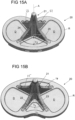
- Fig. 15A, 15B and Fig. 15C show the distal surface D of the tibial tray 20.
- Fig. 15A shows a view from the anterior side
- Fig. 15B shows a view from the posterior side
- Fig. 15C shows a top view of the distal surface D.
- the tibial tray structure 21 is essentially an X-shaped structure, in which the angle ⁇ 1 between the first and second shaft wall elements 22, 23 differs from angle ⁇ 2 between the third and fourth shaft wall elements 24, 25.
- the angle ⁇ 1 between the first and second shaft wall elements 22, 23 facing the posterior side is smaller than the angle ⁇ 2 between the third and fourth haft wall elements 24, 25.
- the angle ⁇ 1 between the first and second shaft wall elements 22, 23 is less than 90°, i.e. 80° (see Fig. 15B ); the angle ⁇ 2 between the third and fourth shaft wall elements 22, 23 is larger than 90°, i.e. 120°.
- the angles ⁇ 1 , ⁇ 2 are 110° and 70° respectively.
- the central fixation elements 1 had a shape with two symmetry axes, one along the long axis and on axis perpendicular to this axis.
- Fig 16A, 16B an embodiment of a tibial tray 20 is shown which deviates from this pattern.
- FIG. 16A, 16B an embodiment is shown in which the central fixation elements 1 have a wider lateral cross-section towards the anterior side than towards the posterior side. Hence, the long sidewalls of each of the central fixation elements 1 are converging towards the anterior side. The inner sidewalls of the central fixation elements 1 are not parallel and are diverging towards the posterior of the tibial tray 20, whereas the outer sidewalls are essentially parallel.
- a variant embodiment of the tibial tray 20 is shown, as the central fixation elements 1 are shaped differently.
- the outer sidewalls of the central fixation elements 1 are parallel to each other and there are two symmetry axes, as in the embodiment shown in Fig. 9 .
- the inner sidewalls are not linear over the complete lengths. Towards the anterior and posterior side, the sidewalls are converging, towards the middle there are diverging.
- the anterior fixation element 2 of the embodiments shown in Fig. 16A, 16B and 17 are shaped as the embodiment shown in Fig. 9 .
- the posterior fixation elements 3 of the embodiments shown in Fig. 16A, 16B and 17 are shaped differently.
- the sidewalls of the posterior element 3 are tilted by an angle between 0 and 45°, in particular between 0 and 30° relative to a plane that is perpendicular to the proximal plane P.
- the sidewalls and the anterior wall of the of the at least one posterior element 3 comprise an undercut.
- FIG. 18A, 18B cross-sections in a frontal plane N (see e.g. Fig. 9A ) are shown for one embodiment.
- Fig. 18A shows a view in the anterior direction, i.e. the anterior fixation element 2 can be seen behind the central fixation elements 1, which are shown in cross-section.
- Fig. 18B shows a view onto the same frontal plane N but into the posterior direction.
- the cross-sections of the central fixation elements 1 show that they comprise central fixation element recesses 12 (undercuts) at the transition to the proximal surface P and along the inner sidewalls.
- the central fixation element recesses 12 here grooves with a constant radius.
- the central fixation element recesses 12 can be also on the outer sidewalls of the central fixation elements 1 or only in the outer sidewalls.
- Fig. 18A, 18B also show cement holding structures 28 which will be described in more detail in connection with Fig. 20A and 20B .
- Fig. 19 shows a schematic representation of a view into the anterior direction with the tibial tray structure 21 (here a T-structure) pointing upwards in the distal direction.
- This representation is not shown as a particular embodiment of a tibial tray 20 but it is intended to indicate how the shape of the outer rim 26 of the sidewalls (e.g. as in Fig. 4 and 5 ) can be generated.
- the outer rim 26 follows a strictly monotonous curve with inflection points. A possible generation of this curve is described below by a using a number of line segments M1, M2, M3, M4, M5 which are connecting the distal plane D with the distal tip of the tibial tray shaft structure 21.
- the first line segment M1 is connecting the distal plane D with a first point P1 in the distal plane D.
- the first point P1 is laterally positioned at about 68% of the distance from the medial plane M (see Fig. 9A ) and the and the outermost point of the lateral rim.
- the inclination of the first line segment M1 is about 20° as measured from the distal plane D.
- the first point P1 is laterally positioned within a range of 55 to 75% of the distance from the medial plane M to the outermost point of the lateral rim.
- the inclination of the first line segment M1 can also be in the range between 15° to 30° as measured from the distal plane D.
- the embodiments can be combined.
- the second line segment M2 is connecting the first point P1 with a second point P2 above the distal plane D.
- the second point P2 is vertically positioned at about 15% of the distance from the distal plane D to the parallel plane with the distal-most point of the tibial tray shaft structure 21.
- the inclination of the second line segment M2 is about 40° as measured from the distal plane D.
- the second point P2 is vertically positioned within a range of 10 to 20% of the distance from the distal plane D to the parallel plane with the distal-most point of the tibial tray shaft structure 21.
- the inclination of the second line segment M2 can also be in the range between 30° to 50° as measured from the distal plane D.
- the embodiments can be combined.
- the third line segment M3 is connecting the second point P2 with a third point P3 above the distal plane D.
- the third point P3 is vertically positioned at about 33% of the distance from the distal plane D to the parallel plane with the distal-most point of the tibial tray shaft structure 21.
- the inclination of the third line segment M3 is about 60° as measured from the distal plane D.
- the third point P3 is vertically positioned within a range of 25 to 40% of the distance from the distal plane D to the parallel plane with the distal-most point of the tibial tray shaft structure 21.
- the inclination of the third line segment M3 can also be in the range between 45° to 70° as measured from the distal plane D.
- the embodiments can be combined.
- the fourth line segment M4 is connecting the third point P3 with a fourth point P4 above the distal plane D.
- the fourth point P4 is vertically positioned at about 50% of the distance from distal plane D to the parallel plane with the distal-most point of the tibial tray shaft structure 21.
- the inclination of the fourth line segment M4 is about 50° as measured from the distal plane D.
- the fourth point P4 is vertically positioned within a range of 40 to 60% of the distance from the distal plane D to the parallel plane with the distal-most point of the tibial tray shaft structure 21.
- the inclination of the fourth line segment M4 can also be in the range between 40° to 60° as measured from the distal plane D.
- the embodiments can be combined.
- the fifth line segment M5 is connecting the fourth point P4 with a point at the central structure of the tibial tray shaft 21.
- the inclination of the fifth line segment M5 is about 75° as measured from the distal plane D. In other embodiments, the inclination of the fifth line segment M5 is in the range between 50 to 80° as measured from the distal plane D. The embodiments can be combined.
- the line segments M1, M2, M3, M4, M5 have varying inclinations, so that in roughly the middle, the inclination of the fourth line segment M4 is steeper than that of the third line segment M3.
- the points defining the line segments can be fitted with smooth curve, such as a polynom or a spline curve to generate the smooth outline of the outer rim 26 of one of the tibial tray shaft structures 21, i.e. the two lateral shaft all elements in the T-structure are shown in Fig. 19 .
- smooth curve such as a polynom or a spline curve to generate the smooth outline of the outer rim 26 of one of the tibial tray shaft structures 21, i.e. the two lateral shaft all elements in the T-structure are shown in Fig. 19 .
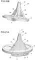
- Fig. 20A and 20B show an embodiment of a tibial tray 20 in perspective views.
- the embodiment has the features as described above, but the tibial shaft structure 21 - here a T-structure - comprises relatively close to the distal surface D cement holding structures 23.
- the anterior side - best seen in Fig. 20A - comprises a groove as cement holding structure 28 across the two wall elements.
- the posterior side - best seen in Fig. 20B - comprises two grooves as cement holding structure 28 each extending over two wall elements, i.e. traversing the rounded corner between the wall elements.
- the cement holding structures 28 are designed here as rounded grooves which are easy to manufacture. In other embodiments, they can also comprise or consist of other shapes, e.g. grooves with sharp corners or holes with round or polygonal cross-sections.
- a tibial tray 20 which is a variant of the above-described embodiments, such as the ones shown in Fig. 20A , 20B , but here without the cement holding structure 23.
- the tibial tray shaft structure 21 comprises a vertical cylinder-shaped base shaft structure 29 extending around the axis A of the tibial tray shaft structure 21.
- the diameter of this base shaft structure 29 is between 5 to 8 mm, in particular depending on the size of the tibial tray 20.
- the diameter can vary in discrete steps, such as 5 mm, 6 mm, 7mm, and 8 mm.
- the cross-section of the base shaft structure 29 does not have to be circular. Other shapes, as e.g. elliptical or polygonal, are also possible.
- Fig. 21B shows the posterior view of a tibial tray 20 (T-structure).
- the radius of the curved surface 13 close to the base shaft structure 29 is between 1 and 9 mm, in particular between 3 and 5 mm. Similar curved surfaces with the same radii would be used between wall elements in X-structures or Y-structures.
- Fig. 21A shows the anterior view of the T-structure shown in Fig. 21B .
- the cylindrical base shaft structure 29 extends into the anterior direction beyond the two frontal wall elements 22, 23.
- the curved surface 23 at the frontal side here is between 10 mm and 30 mm, in particular 20 mm.
- Those curved surfaces 13 prevent sharp corners which improves inter alia the insertabilty of the tibial tray.
- proximal surface P of a tibial tray 20 is shown which comprises a variation in the design of the anterior fixation element 2 over the embodiments described above.
- the central fixation elements 1 and the posterior fixation element 3 have been described in one way or the other e.g. in Fig. 9 or 16A , so that reference can be made to the above description.
- the anterior fixation element 2 comprises two form-fitting elements 5 for receiving a corresponding part of the tibial insert 30 (not shown here, see Fig. 12A, 12B e.g. for the snap-in process of the tibial tray).
- the form-fitting elements 5 are essentially holes with a rectangular cross-section.
- the form-fitting elements 31 for the anterior fixation have a shape which corresponds to the form-fitting elements 5 (e.g. the rectangular holes).
- guiding surfaces 11 are provided for on the proximal surface of the anterior fixation device 5.
- the guiding surfaces 11 are planes inclined by 5° to 45° against the horizontal plane, in particular inclined by 30°. In other embodiments, not shown here.
- the guiding surface are curved or have a plane part.
- the form-fitting elements 31 of the tibial insert 30 protrude into the anterior direction.
- the form-fitting elements 31 first rest on the upper parts of the guiding surfaces 11.
- the form-fitting elements 31 are guided downwards along the guiding surfaces 11 and eventually snap into the holes forming the form-fitting elements of the anterior fixation element 5 for a secure fit.
- the guiding surfaces 11 prevent compromising the form-fitting elements 5 during insertion and make a secure snap-in easier.
- the lateral width of the guiding surface is the same or about the same as the lateral width of the form-fitting elements 5 in the anterior fixation element 2.
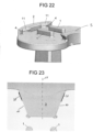
- a detail of the posterior fixation element 3 is shown in a top view, i.e. in the direction of the proximal surface P.
- the cross-section of the posterior fixation element 3 comprises two sidewalls 10 that are inclined towards the medial plane M. Each of the sidewalls 10 is angled by about 20° against the medial plane M. In the embodiment shown, there is a deliberate angular mismatch between the sidewalls 10 of the posterior fixation element 3 and the corresponding sidewalls of the tibial insert 30 (not shown here).
- the sidewalls of the tibial insert 30, which are intended to get into contact or into a form-fit with the sidewalls 10 of the posterior fixation element 3 have a lightly different inclination than the sidewalls 10, an angular mismatch is created causing a closer contact or a force-fit at some parts along the sidewalls 10 and a looser fit in others.
- the angle of the sidewalls of posterior fixation element 3 is wider (e.g. by about 1°) than the corresponding angle in the recess in the tibial insert 30. This causes a form-fit, i.e. a tighter fit in the posterior area.
- the press-fitting region 38 in this area is indicated in Fig. 23 . Not only enables this angular mismatch an easier assembly, but it also reduces micromovements in the posterior regions.
- the press-fit region 38 is created by widening the posterior part of the posterior fixation element 3.
Landscapes
- Health & Medical Sciences (AREA)
- Orthopedic Medicine & Surgery (AREA)
- Cardiology (AREA)
- Oral & Maxillofacial Surgery (AREA)
- Transplantation (AREA)
- Engineering & Computer Science (AREA)
- Biomedical Technology (AREA)
- Heart & Thoracic Surgery (AREA)
- Vascular Medicine (AREA)
- Life Sciences & Earth Sciences (AREA)
- Animal Behavior & Ethology (AREA)
- General Health & Medical Sciences (AREA)
- Public Health (AREA)
- Veterinary Medicine (AREA)
- Physical Education & Sports Medicine (AREA)
- Prostheses (AREA)
Priority Applications (6)
| Application Number | Priority Date | Filing Date | Title |
|---|---|---|---|
| EP23178474.5A EP4473945A1 (fr) | 2023-06-09 | 2023-06-09 | Plateau tibial ayant une structure de tige de plateau tibial et une articulation artificielle du genou |
| AU2024285613A AU2024285613A1 (en) | 2023-06-09 | 2024-06-07 | Tibial tray with a tibial tray shaft structure and an artificial knee joint |
| PCT/EP2024/065766 WO2024251964A1 (fr) | 2023-06-09 | 2024-06-07 | Plateau tibial avec structure de tige de plateau tibial et articulation artificielle du genou |
| EP24733530.0A EP4724013A1 (fr) | 2023-06-09 | 2024-06-07 | Plateau tibial avec structure de tige de plateau tibial et articulation artificielle du genou |
| KR1020257036607A KR20260021592A (ko) | 2023-06-09 | 2024-06-07 | 경골 트레이 샤프트 구조를 갖는 경골 트레이 및 인공 슬관절 |
| CN202480038006.XA CN121358437A (zh) | 2023-06-09 | 2024-06-07 | 具有胫骨托盘轴结构的胫骨托盘和人工膝关节 |
Applications Claiming Priority (1)
| Application Number | Priority Date | Filing Date | Title |
|---|---|---|---|
| EP23178474.5A EP4473945A1 (fr) | 2023-06-09 | 2023-06-09 | Plateau tibial ayant une structure de tige de plateau tibial et une articulation artificielle du genou |
Publications (1)
| Publication Number | Publication Date |
|---|---|
| EP4473945A1 true EP4473945A1 (fr) | 2024-12-11 |
Family
ID=86760287
Family Applications (2)
| Application Number | Title | Priority Date | Filing Date |
|---|---|---|---|
| EP23178474.5A Withdrawn EP4473945A1 (fr) | 2023-06-09 | 2023-06-09 | Plateau tibial ayant une structure de tige de plateau tibial et une articulation artificielle du genou |
| EP24733530.0A Pending EP4724013A1 (fr) | 2023-06-09 | 2024-06-07 | Plateau tibial avec structure de tige de plateau tibial et articulation artificielle du genou |
Family Applications After (1)
| Application Number | Title | Priority Date | Filing Date |
|---|---|---|---|
| EP24733530.0A Pending EP4724013A1 (fr) | 2023-06-09 | 2024-06-07 | Plateau tibial avec structure de tige de plateau tibial et articulation artificielle du genou |
Country Status (5)
| Country | Link |
|---|---|
| EP (2) | EP4473945A1 (fr) |
| KR (1) | KR20260021592A (fr) |
| CN (1) | CN121358437A (fr) |
| AU (1) | AU2024285613A1 (fr) |
| WO (1) | WO2024251964A1 (fr) |
Citations (6)
| Publication number | Priority date | Publication date | Assignee | Title |
|---|---|---|---|---|
| EP1154741A2 (fr) * | 1998-11-04 | 2001-11-21 | Blake A. Stamper | Prothese orthopedique avec anneau de compression en gomme |
| US20140200674A1 (en) * | 2012-11-21 | 2014-07-17 | Krishnachandra Chandrashanker Mehta | Knee replacement prosthetic |
| US20160278929A1 (en) * | 2015-03-23 | 2016-09-29 | Modal Manufacturing, LLC | Knee implants and instruments |
| US20200121465A1 (en) * | 2018-10-19 | 2020-04-23 | Roy D. Bloebaum | Osteolysis-resistant cementless joint implant with improved stability and seating function |
| EP3626209B1 (fr) | 2017-05-09 | 2021-04-28 | DePuy Ireland Unlimited Company | Plateau tibial ayant des fonctions de fixation |
| US20210338440A1 (en) * | 2020-04-30 | 2021-11-04 | DePuy Synthes Products, Inc. | Orthopaedic knee implant system with controlled stiffness |
-
2023
- 2023-06-09 EP EP23178474.5A patent/EP4473945A1/fr not_active Withdrawn
-
2024
- 2024-06-07 AU AU2024285613A patent/AU2024285613A1/en active Pending
- 2024-06-07 WO PCT/EP2024/065766 patent/WO2024251964A1/fr not_active Ceased
- 2024-06-07 KR KR1020257036607A patent/KR20260021592A/ko active Pending
- 2024-06-07 EP EP24733530.0A patent/EP4724013A1/fr active Pending
- 2024-06-07 CN CN202480038006.XA patent/CN121358437A/zh active Pending
Patent Citations (6)
| Publication number | Priority date | Publication date | Assignee | Title |
|---|---|---|---|---|
| EP1154741A2 (fr) * | 1998-11-04 | 2001-11-21 | Blake A. Stamper | Prothese orthopedique avec anneau de compression en gomme |
| US20140200674A1 (en) * | 2012-11-21 | 2014-07-17 | Krishnachandra Chandrashanker Mehta | Knee replacement prosthetic |
| US20160278929A1 (en) * | 2015-03-23 | 2016-09-29 | Modal Manufacturing, LLC | Knee implants and instruments |
| EP3626209B1 (fr) | 2017-05-09 | 2021-04-28 | DePuy Ireland Unlimited Company | Plateau tibial ayant des fonctions de fixation |
| US20200121465A1 (en) * | 2018-10-19 | 2020-04-23 | Roy D. Bloebaum | Osteolysis-resistant cementless joint implant with improved stability and seating function |
| US20210338440A1 (en) * | 2020-04-30 | 2021-11-04 | DePuy Synthes Products, Inc. | Orthopaedic knee implant system with controlled stiffness |
Also Published As
| Publication number | Publication date |
|---|---|
| WO2024251964A1 (fr) | 2024-12-12 |
| CN121358437A (zh) | 2026-01-16 |
| EP4724013A1 (fr) | 2026-04-15 |
| KR20260021592A (ko) | 2026-02-13 |
| AU2024285613A1 (en) | 2025-09-25 |
Similar Documents
| Publication | Publication Date | Title |
|---|---|---|
| AU2005200997B2 (en) | Intervertebral implant | |
| US7494510B2 (en) | Leaflike shaft of a hip-joint prosthesis for anchoring in the femur | |
| EP3142609B1 (fr) | Prothèse de remplacement total de cheville | |
| AU613243B2 (en) | Prosthetic device and method of implantation | |
| US7455693B2 (en) | Leaflike shaft of a hip-joint prosthesis for anchoring in the femur | |
| US5147408A (en) | Prosthetic device and method of implantation | |
| US20100100190A1 (en) | Tibial tray having a reinforcing member | |
| US20100100191A1 (en) | Tibial Tray Having a Reinforcing Member | |
| EP3627999B1 (fr) | Glénoïde augmenté avec rainure | |
| WO2023003929A1 (fr) | Dispositifs d'arthroplastie de genou | |
| EP4473945A1 (fr) | Plateau tibial ayant une structure de tige de plateau tibial et une articulation artificielle du genou | |
| US6613094B2 (en) | Shaft for anchoring a hip joint prosthesis in the femur | |
| JP2024519476A (ja) | 外科用切断ガイド | |
| US20250318935A1 (en) | Tibial Tray, Tibial Insert and an Artificial Knee Joint | |
| AU2007279177B2 (en) | Intervertebral implant intended for osseous fusion | |
| US20260041559A1 (en) | Unicompartmental arthroplasty femoral component | |
| WO2025219363A1 (fr) | Systèmes et procédés pour implants tibiaux | |
| CN115844596A (zh) | 一种胫骨托固定结构及胫骨托组件 | |
| WO2023131781A1 (fr) | Perfectionnements apportés ou se rapportant à un appareil d'implant | |
| WO2026050360A1 (fr) | Système de tige destiné à être utilisé dans une chirurgie de remplacement de cheville total et ses procédés d'utilisation |
Legal Events
| Date | Code | Title | Description |
|---|---|---|---|
| PUAI | Public reference made under article 153(3) epc to a published international application that has entered the european phase |
Free format text: ORIGINAL CODE: 0009012 |
|
| STAA | Information on the status of an ep patent application or granted ep patent |
Free format text: STATUS: THE APPLICATION HAS BEEN PUBLISHED |
|
| AK | Designated contracting states |
Kind code of ref document: A1 Designated state(s): AL AT BE BG CH CY CZ DE DK EE ES FI FR GB GR HR HU IE IS IT LI LT LU LV MC ME MK MT NL NO PL PT RO RS SE SI SK SM TR |
|
| STAA | Information on the status of an ep patent application or granted ep patent |
Free format text: STATUS: THE APPLICATION IS DEEMED TO BE WITHDRAWN |
|
| 18D | Application deemed to be withdrawn |
Effective date: 20250612 |