EP4474178A1 - Hülse für eine luftfeder für ein fahrzeug und luftfeder für ein fahrzeug damit - Google Patents
Hülse für eine luftfeder für ein fahrzeug und luftfeder für ein fahrzeug damit Download PDFInfo
- Publication number
- EP4474178A1 EP4474178A1 EP24178653.2A EP24178653A EP4474178A1 EP 4474178 A1 EP4474178 A1 EP 4474178A1 EP 24178653 A EP24178653 A EP 24178653A EP 4474178 A1 EP4474178 A1 EP 4474178A1
- Authority
- EP
- European Patent Office
- Prior art keywords
- sleeve
- vehicle
- circumferential portion
- air spring
- thickness
- Prior art date
- Legal status (The legal status is an assumption and is not a legal conclusion. Google has not performed a legal analysis and makes no representation as to the accuracy of the status listed.)
- Pending
Links
Images



Classifications
-
- B—PERFORMING OPERATIONS; TRANSPORTING
- B60—VEHICLES IN GENERAL
- B60G—VEHICLE SUSPENSION ARRANGEMENTS
- B60G11/00—Resilient suspensions characterised by arrangement, location or kind of springs
- B60G11/26—Resilient suspensions characterised by arrangement, location or kind of springs having fluid springs only, e.g. hydropneumatic springs
- B60G11/28—Resilient suspensions characterised by arrangement, location or kind of springs having fluid springs only, e.g. hydropneumatic springs characterised by means specially adapted for attaching the spring to axle or sprung part of the vehicle
-
- B—PERFORMING OPERATIONS; TRANSPORTING
- B60—VEHICLES IN GENERAL
- B60G—VEHICLE SUSPENSION ARRANGEMENTS
- B60G11/00—Resilient suspensions characterised by arrangement, location or kind of springs
- B60G11/26—Resilient suspensions characterised by arrangement, location or kind of springs having fluid springs only, e.g. hydropneumatic springs
- B60G11/27—Resilient suspensions characterised by arrangement, location or kind of springs having fluid springs only, e.g. hydropneumatic springs wherein the fluid is a gas
-
- F—MECHANICAL ENGINEERING; LIGHTING; HEATING; WEAPONS; BLASTING
- F16—ENGINEERING ELEMENTS AND UNITS; GENERAL MEASURES FOR PRODUCING AND MAINTAINING EFFECTIVE FUNCTIONING OF MACHINES OR INSTALLATIONS; THERMAL INSULATION IN GENERAL
- F16F—SPRINGS; SHOCK-ABSORBERS; MEANS FOR DAMPING VIBRATION
- F16F9/00—Springs, vibration-dampers, shock-absorbers, or similarly-constructed movement-dampers using a fluid or the equivalent as damping medium
- F16F9/02—Springs, vibration-dampers, shock-absorbers, or similarly-constructed movement-dampers using a fluid or the equivalent as damping medium using gas only or vacuum
-
- F—MECHANICAL ENGINEERING; LIGHTING; HEATING; WEAPONS; BLASTING
- F16—ENGINEERING ELEMENTS AND UNITS; GENERAL MEASURES FOR PRODUCING AND MAINTAINING EFFECTIVE FUNCTIONING OF MACHINES OR INSTALLATIONS; THERMAL INSULATION IN GENERAL
- F16F—SPRINGS; SHOCK-ABSORBERS; MEANS FOR DAMPING VIBRATION
- F16F9/00—Springs, vibration-dampers, shock-absorbers, or similarly-constructed movement-dampers using a fluid or the equivalent as damping medium
- F16F9/02—Springs, vibration-dampers, shock-absorbers, or similarly-constructed movement-dampers using a fluid or the equivalent as damping medium using gas only or vacuum
- F16F9/04—Springs, vibration-dampers, shock-absorbers, or similarly-constructed movement-dampers using a fluid or the equivalent as damping medium using gas only or vacuum in a chamber with a flexible wall
- F16F9/0445—Springs, vibration-dampers, shock-absorbers, or similarly-constructed movement-dampers using a fluid or the equivalent as damping medium using gas only or vacuum in a chamber with a flexible wall characterised by intermediate rings or other not embedded reinforcing elements
-
- F—MECHANICAL ENGINEERING; LIGHTING; HEATING; WEAPONS; BLASTING
- F16—ENGINEERING ELEMENTS AND UNITS; GENERAL MEASURES FOR PRODUCING AND MAINTAINING EFFECTIVE FUNCTIONING OF MACHINES OR INSTALLATIONS; THERMAL INSULATION IN GENERAL
- F16F—SPRINGS; SHOCK-ABSORBERS; MEANS FOR DAMPING VIBRATION
- F16F9/00—Springs, vibration-dampers, shock-absorbers, or similarly-constructed movement-dampers using a fluid or the equivalent as damping medium
- F16F9/02—Springs, vibration-dampers, shock-absorbers, or similarly-constructed movement-dampers using a fluid or the equivalent as damping medium using gas only or vacuum
- F16F9/04—Springs, vibration-dampers, shock-absorbers, or similarly-constructed movement-dampers using a fluid or the equivalent as damping medium using gas only or vacuum in a chamber with a flexible wall
- F16F9/0454—Springs, vibration-dampers, shock-absorbers, or similarly-constructed movement-dampers using a fluid or the equivalent as damping medium using gas only or vacuum in a chamber with a flexible wall characterised by the assembling method or by the mounting arrangement, e.g. mounting of the membrane
-
- F—MECHANICAL ENGINEERING; LIGHTING; HEATING; WEAPONS; BLASTING
- F16—ENGINEERING ELEMENTS AND UNITS; GENERAL MEASURES FOR PRODUCING AND MAINTAINING EFFECTIVE FUNCTIONING OF MACHINES OR INSTALLATIONS; THERMAL INSULATION IN GENERAL
- F16F—SPRINGS; SHOCK-ABSORBERS; MEANS FOR DAMPING VIBRATION
- F16F9/00—Springs, vibration-dampers, shock-absorbers, or similarly-constructed movement-dampers using a fluid or the equivalent as damping medium
- F16F9/32—Details
- F16F9/3207—Constructional features
-
- B—PERFORMING OPERATIONS; TRANSPORTING
- B60—VEHICLES IN GENERAL
- B60G—VEHICLE SUSPENSION ARRANGEMENTS
- B60G2202/00—Indexing codes relating to the type of spring, damper or actuator
- B60G2202/10—Type of spring
- B60G2202/15—Fluid spring
- B60G2202/152—Pneumatic spring
-
- B—PERFORMING OPERATIONS; TRANSPORTING
- B60—VEHICLES IN GENERAL
- B60G—VEHICLE SUSPENSION ARRANGEMENTS
- B60G2206/00—Indexing codes related to the manufacturing of suspensions: constructional features, the materials used, procedures or tools
- B60G2206/01—Constructional features of suspension elements, e.g. arms, dampers, springs
- B60G2206/40—Constructional features of dampers and/or springs
- B60G2206/42—Springs
- B60G2206/424—Plunger or top retainer construction for bellows or rolling lobe type air springs
-
- B—PERFORMING OPERATIONS; TRANSPORTING
- B60—VEHICLES IN GENERAL
- B60G—VEHICLE SUSPENSION ARRANGEMENTS
- B60G2206/00—Indexing codes related to the manufacturing of suspensions: constructional features, the materials used, procedures or tools
- B60G2206/01—Constructional features of suspension elements, e.g. arms, dampers, springs
- B60G2206/70—Materials used in suspensions
- B60G2206/71—Light weight materials
- B60G2206/7104—Thermoplastics
-
- B—PERFORMING OPERATIONS; TRANSPORTING
- B60—VEHICLES IN GENERAL
- B60G—VEHICLE SUSPENSION ARRANGEMENTS
- B60G2206/00—Indexing codes related to the manufacturing of suspensions: constructional features, the materials used, procedures or tools
- B60G2206/01—Constructional features of suspension elements, e.g. arms, dampers, springs
- B60G2206/80—Manufacturing procedures
- B60G2206/82—Joining
- B60G2206/8201—Joining by welding
Definitions
- the present disclosure relates to a sleeve for an air spring for a vehicle and the air spring for a vehicle including the same, and more specifically, to a sleeve for an air spring for a vehicle which has improved the property and rigidity of the air spring without a complex reinforcing fiber process, and the air spring for a vehicle including the same.
- a suspension for a vehicle is provided between a vehicle body and a wheel to connect the vehicle body and the wheel as rigid bodies by one or multiple links.
- the suspension is supported by a spring, a shock absorber and the like in a vertical direction, and serves to appropriately balance a mechanical relative movement between the vehicle body and the wheel by appropriately combining high rigidity and flexibility in other directions.
- the suspension needs to satisfy the following basic conditions. That is, the suspension needs to effectively block irregular inputs generated from a road surface when the vehicle is travelling, thus providing a comfortable ride quality to passengers.
- the suspension needs to provide driving convenience by appropriately control the shaking of the vehicle body caused by a driving behavior of a driver and unevenness of the road surface. Further, when the vehicle travels on the unevenness road surface, the suspension needs to maintain a vertical load acting on each tire at a contact surface with the unevenness road surface at an appropriate level, thus ensuring the driving operation and stability of the vehicle during turning and braking.
- an air suspension has been widely applied to a deluxe vehicle.
- the air suspension improves the ride quality by changing a constant of an air spring to change a volume of a sleeve constituting the air spring, and automatically maintains a height of the vehicle by changing an amount of air.
- a sleeve in the related art needs to have excellent durability.
- a sleeve in the related art needs to have improved durability.
- a rubber sleeve in the related art is manufactured by a complex reinforcing fiber process to improve durability and reinforce rigidity. This may entail significant deterioration in manufacturing efficiency of the sleeve.
- Patent Document 0001 European Patent No. 2,090,801 (January 26, 2009 )
- the present disclosure was made to solve the above-mentioned matters, and the present disclosure is for the purpose of providing a sleeve for an air spring for a vehicle which has improved spring property and rigidity without a complex reinforcing fiber process, and the air spring for a vehicle including the same.
- the present disclosure is for the purpose of providing a sleeve for an air spring for a vehicle in which stress of a material may be easily managed by controlling an expansion rate of the sleeve, and the air spring for a vehicle including the same.
- the present disclosure is for the purpose of providing a sleeve for an air spring for a vehicle in which product performance may be improved by enhancing a degree of freedom in design, and the air spring for a vehicle including the same.
- the present disclosure is for the purpose of providing a sleeve for an air spring for a vehicle in which the sleeve may be manufactured to be divided into a plurality of sleeves by injection molding to improve a flow of the injection molding of each sleeve and improve a quality of each sleeve, and the air spring for a vehicle including the same.
- a sleeve 500 for an air spring for a vehicle may include at least an upper sleeve 520 and a lower sleeve (540, 640), in which an upper circumferential portion 522 of the upper sleeve 520 may be coupled to a top mount, a lower circumferential portion (544, 644) of the lower sleeve (540, 640) may be coupled to a piston portion, and one of the upper sleeve 520 and the lower sleeve (540, 640) may be formed to have different thicknesses for each section along a longitudinal direction.
- a thickness of the sleeve in a region where a rolling lobe is formed when the piston portion is raised at a maximum may be greater than a thickness of the sleeve in the region where the rolling lobe is formed when the piston portion is lowered at a maximum.
- the thickness of the sleeve in the region where the rolling lobe is formed when the piston portion is raised at a maximum may be greater than a thickness of the sleeve in the region where the rolling lobe is formed when the vehicle is stopped in a drivable state.
- the lower circumferential portion 524 of the upper sleeve 520 and the upper circumferential portion 542 of the lower sleeve 540 may be arranged to overlap each other, and in the overlapping region where the lower circumferential portion 524 of the upper sleeve 520 and the upper circumferential portion 542 of the lower sleeve 540 are arranged to overlap each other, a thickness of the upper sleeve 520 and a thickness of the lower sleeve 540 may be substantially identical to each other, or the sleeve arranged inwardly in the overlapping region may be greater than a thickness of the sleeve arranged outwardly in the overlapping region.
- the one of the upper sleeve 520 and the lower sleeve (540, 640) formed to have the different thicknesses for each section may be configured to have at least a first section in which an inner diameter is constant in the longitudinal direction and a second section in which the inner diameter decreases constantly downward in the longitudinal direction.
- An inner-diameter transition section may be provided between the first section and the second section to connect the first section and the second section.
- the sleeve may be formed to have the different thicknesses such that, when the piston portion is raised at the maximum, the sleeve has a maximum thickness in the region where the rolling lobe is formed.
- the sleeve may be formed to have the different thicknesses such that, when the vehicle is stopped in a drivable state, the sleeve has a minimum thickness in the region where the rolling lobe is formed.
- the sleeve may be formed to have the different thicknesses such that, when the piston portion is lowered at the maximum, the sleeve has a minimum thickness in the region where the rolling lobe is formed.
- the maximum thickness may be in a range of 3.0 to 7.0 millimeter (mm).
- the minimum thickness may be in a range of 1.0 to 4.0 mm.
- the sleeve formed to have the different thicknesses may be the lower sleeve (540, 640).
- an air spring for a vehicle may include: the sleeve (500, 600) configured as above; a top mount mounted on an upper circumferential portion (522, 622) of an upper sleeve (520, 620); and a piston portion mounted on a lower circumferential portion (544, 644) of a lower sleeve (540, 640).
- a sleeve for an air spring for a vehicle is configured to have different thicknesses for each section in a longitudinal direction, which makes it possible to improve the property and rigidity of the air spring without a complex reinforcing fiber process.
- a sleeve to be divided into a plurality of sleeves by injection molding, it is possible to improve a flow of the injection molding of each sleeve, improve a quality of each sleeve, enhance a degree of freedom in design and improve product performance.
- the second constituent element may be named as the first constituent element in another description of the specification.
- the term “and/or” may be used to represent a combination of a plurality of related items described herein or at least one of the plurality of related items.
- the constituent element when a constituent element is referred to as being “coupled” or “connected” to another constituent element, the constituent element may be directly coupled or directly connected to the another constituent element, but yet another constituent element may be provided between the constituent element and the another constituent element.
- a constituent element when a constituent element is referred to as being “directly coupled” or “directly connected” to another constituent element, yet another constituent element may not be provided between the constituent element and the another constituent element.
- the terms used herein are merely used to describe specific example embodiments and do not limit the present disclosure.
- An air spring may be arranged between a top mount and a piston portion to act as a spring.
- the air spring may include a housing and a sleeve.
- one end of the sleeve may be hermetically fixed to the top mount and the other end thereof is hermetically fixed to the piston portion.
- the sleeve may be enclosed by the housing.
- the sleeve is an air bag whose volume may vary with up and down movement of the piston portion. That is, the volume of the sleeve, which has a constant internal pressure, varies with the up and down movement. With the variation in the internal pressure, the sleeve acts as the spring.
- one end of the sleeve may be hermetically fixed to the top mount and the other end thereof may be hermetically fixed to an inner surface of the piston portion.
- the sleeve may be enclosed by the housing.
- a bent portion of the sleeve that is, a portion where a rolling lobe is formed, may be rolled together with the piston portion to be formed in a round shape. Accordingly, air inside the sleeve is compressed so that the sleeve acts as an air spring.
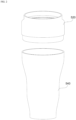
- FIG. 1 is a perspective view of a sleeve according to an example embodiment of the present disclosure.
- the sleeve illustrated in FIG. 1 is a sleeve before being mounted to a top mount and a piston portion to form a lobe.
- FIG. 2 is an exploded perspective view of the sleeve illustrated in FIG. 1 .
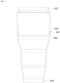
- FIG. 3 is a cross-sectional view of the sleeve illustrated in FIG. 1 .
- a sleeve 500 for an air spring for a vehicle may be entirely formed in a cylindrical shape.
- the sleeve 500 may include at least an upper sleeve 520 and a lower sleeve 540.
- An upper circumferential portion 522 of the upper sleeve 520 may be coupled to the top mount and a lower circumferential portion 524 of the upper sleeve 520 may be coupled to an upper circumferential portion 542 of the lower sleeve 540.
- a lower circumferential portion 544 of the lower sleeve 540 is coupled to the piston portion.
- the lower sleeve 540 out of the upper sleeve 520 and the lower sleeve 540 is configured to encompass a region where the rolling lobe is formed.
- the upper sleeve 520 may be configured to encompass the region where the rolling lobe is formed.
- the sleeve 500 may be manufactured to be divided into a first sleeve encompassing the region where the rolling lobe is formed, and a second sleeve not encompassing the area. With this configuration, it is possible to improve a degree of freedom of design of the sleeve 500 and enhance manufacturing efficiency of the sleeve 500 while satisfying high rigidity required for the sleeve 500.
- thermoplastic elastomer material may be molded and reused by injection, extrusion blow molding, or the like, and has an elastomeric property.
- a stepped portion may be formed along a circumferential direction in one of the lower circumferential portion 524 of the upper sleeve 520 and the upper circumferential portion 542 of the lower sleeve 540 such that the upper sleeve 520 (or the lower sleeve 540) is seated on the lower sleeve 540 (or the upper sleeve 520).
- a stepped portion 546 is illustrated as being formed in the lower circumferential portion 524 of the upper sleeve 520 along the circumferential direction.
- the lower circumferential portion 524 of the upper sleeve 520 and the upper circumferential portion 542 of the lower sleeve 540 may have outwardly-extending flanges, respectively.
- the upper sleeve 620 and the lower sleeve 640 may be manufactured independently of each other with different materials.
- a degree of freedom of material selection may be limited for bonding.
- a stepped portion 668 may be further formed along the circumferential direction in one of the lower circumferential portion 664 of the intermediate sleeve 660 and the upper circumferential portion 642 of the lower sleeve 640 such that the intermediate sleeve 660 (or the lower sleeve 640) is seated on the lower sleeve 640 (or the intermediate sleeve 660).
- the stepped portions 666 and 668 are illustrating as being formed on the upper circumferential portion 662 of the intermediate sleeve 660 and the lower circumferential portion 664 of the intermediate sleeve 660
- the lower circumferential portion 664 of the intermediate sleeve 660 may be attached to the upper circumferential portion 642 of the lower sleeve 640.
- the intermediate sleeve 660 is arranged inward in the overlapping region, and the upper sleeve 620 and the lower sleeve 640 are arranged outward in the overlapping region.
- the intermediate sleeve 660 may be made of a laser-energy absorbable material (for example, carbon black), and the upper sleeve 620 and the lower sleeve 640 may be made of a laser-energy transmissible material.
- a laser-energy absorbable material for example, carbon black
- the lower circumferential portion 624 of the upper sleeve 620 and the upper circumferential portion 662 of the intermediate sleeve 660 may be configured to have outwardly-extending flanges, respectively.
- the lower circumferential portion 624 of the upper sleeve 620 may be attached to the upper circumferential portion 662 of the intermediate sleeve 660.
- the lower circumferential portion 664 of the intermediate sleeve 660 and the upper circumferential portion 642 of the lower sleeve 640 may be configured to have outwardly-extending flanges, respectively.
- the lower circumferential portion 664 of the intermediate sleeve 660 may be attached to the upper circumferential portion 642 of the lower sleeve 640.
- FIG. 7 is a cross-sectional view of the lower sleeve, which explains a change in thickness of the lower sleeve along a longitudinal direction of the lower sleeve.
- a configuration of the lower sleeve as illustrated in FIG. 7 may be applied to both the sleeve constituted with the upper sleeve and the lower sleeve of FIG. 1 , and the sleeve constituted with the upper sleeve, the intermediate sleeve and the lower sleeve of FIG. 4 .
- a change in thickness of the lower sleeve will be mainly described later, such a change in thickness may be applied to the upper sleeve.
- the sleeve (in particular, the lower sleeve) according to the present disclosure functions as an air bag whose volume may vary with up and down movement of the piston portion. That is, the volume of the sleeve, which has a constant internal pressure, varies with the up and down movement of the piston portion. With the variation in the volume, the internal pressure also varies.
- the sleeve when the piston portion is raised at a maximum (in a full jounce), the sleeve may have a minimum volume so that the internal pressure of the sleeve is increased. This increases load to be applied to a region where a rolling lobe is formed. Meanwhile, when the piston portion is lowered at a maximum (in a full rebound), the sleeve may have a maximum volume so that the internal pressure thereof is decreased. This reduces reduce the load to be applied to the region where the rolling lobe is formed.
- the sleeve needs to have rigidity for durability, but also requires spring property.
- the lower sleeves (540, 640) may be formed to have different thicknesses for each section along the longitudinal direction.
- a thickness of the sleeve in the region where the rolling love is formed when the piston portion is raised at a maximum may be greater than a thickness of the sleeve in the region where the rolling rob is formed when the piston portion is lowered at a maximum. Further, the thickness of the sleeve in the region where the rolling rob is formed when the piston portion is raised at a maximum may be greater than a thickness of the sleeve in the region where the rolling rob is formed when a vehicle is stopped in a drivable state (when the vehicle is at a normal position).
- the durability of the sleeve may be improved by increasing a thickness the sleeve in a region to which a relatively large load is applied. Further, the spring property of the air spring may be ensured by decreasing a thickness of the sleeve in a region to which a relatively small load is applied.
- the lower sleeve when the piston portion is raised at a maximum, the lower sleeve (540, 640) may be formed to have a maximum thickness in the region in which the rolling lobe is formed.
- the maximum thickness may be in a range of 3.0 to 7.0 mm.
- the lower sleeve (540, 640) when the vehicle is stopped in a drivable state, the lower sleeve (540, 640) may be formed to have a minimum thickness in the region where the rolling rob is formed. Further, when the piston portion is lowered at a maximum, the lower sleeve (540, 640) may be formed to have the minimum thickness in the region where the rolling rob is formed. In order to further enhance the spring property, the lower sleeve (540, 640) may be formed to have the minimum thickness in both the region where the rolling rob is formed when the piston portion is lowered at a maximum and the region where the rolling rob is formed when the vehicle is stopped in a drivable state. As an example, the minimum thickness may be in a range of 1.0 to 4.0 mm.
- the lower circumferential portion 524 of the upper sleeve 520 and the upper circumferential portion 542 of the lower sleeve 540 may be arranged to overlap each other.
- a laser welding may be performed with respect to an overlapping region where the lower circumferential portion 524 of the upper sleeve 520 and the upper circumferential portion 542 of the lower sleeve 540 are arranged to overlap each other, so that the lower circumferential portion 524 and the upper circumferential portion 542 are attached to each other.
- the thickness of the upper sleeve 520 and the thickness of the lower sleeve 540 in the overlapping region may be constant in the longitudinal direction.
- energy of the same intensity needs to be applied to the overlapping region.
- the overlapping region may have a size of 5 millimeter (mm) or more in the longitudinal direction.
- the thickness of the upper sleeve 520 and the thickness of the lower sleeve 540 may be identical to each other. Further, the thickness of the sleeve arranged inwardly in the overlapping region may be greater than that of the sleeve arranged outwardly in the overlapping region.
- the lower sleeve (540, 640) may be configured to have a first section in which an inner diameter is constant in the longitudinal direction, a second section in which the inner diameter decreases constantly downward in the longitudinal direction, a third section in which the inner diameter is constant in the longitudinal direction, a fourth section in which the inner diameter decreases constantly downward in the longitudinal direction, and a fifth section in which the inner diameter is constant in the longitudinal direction, which are sequentially defined from above to below.
- inner-diameter transition sections connecting may be formed to connect between the respective sections described above.
- the thickness of the sleeve is substantially constant in the longitudinal direction. This thickness may be, for example, about 3 mm.
- the second section may have the region where the rolling lobe is formed when the piston portion is raised at a maximum. A thickness of the second section may be at a maximum, for example, about 3.5 mm.
- Each of the third section, the fourth section and the inner-diameter transition section which connects the third section and the fourth section may have a region in which the rolling lobe is formed when the piston portion is lowered at a maximum, and a region in which the rolling lobe is formed when the vehicle is stopped in a drivable state.
- a thickness of each of the third section, the fourth section, the inner-diameter transition section which connects the third section and the fourth section may be about 2.5 mm at a minimum.
Landscapes
- Engineering & Computer Science (AREA)
- Mechanical Engineering (AREA)
- General Engineering & Computer Science (AREA)
- Fluid-Damping Devices (AREA)
- Vehicle Body Suspensions (AREA)
Applications Claiming Priority (2)
| Application Number | Priority Date | Filing Date | Title |
|---|---|---|---|
| KR20230072341 | 2023-06-05 | ||
| KR1020230131038A KR20240173584A (ko) | 2023-06-05 | 2023-09-27 | 차량용 에어 스프링을 위한 슬리브 및 이를 포함하는 차량용 에어 스프링 |
Publications (1)
| Publication Number | Publication Date |
|---|---|
| EP4474178A1 true EP4474178A1 (de) | 2024-12-11 |
Family
ID=91331052
Family Applications (1)
| Application Number | Title | Priority Date | Filing Date |
|---|---|---|---|
| EP24178653.2A Pending EP4474178A1 (de) | 2023-06-05 | 2024-05-29 | Hülse für eine luftfeder für ein fahrzeug und luftfeder für ein fahrzeug damit |
Country Status (4)
| Country | Link |
|---|---|
| US (1) | US20240399808A1 (de) |
| EP (1) | EP4474178A1 (de) |
| JP (1) | JP7847882B2 (de) |
| CN (1) | CN119078425A (de) |
Citations (6)
| Publication number | Priority date | Publication date | Assignee | Title |
|---|---|---|---|---|
| US3727899A (en) * | 1971-04-07 | 1973-04-17 | Air Lift Co | Spring suspension unit particularly for vehicle suspension systems |
| US4807858A (en) * | 1986-06-13 | 1989-02-28 | Bridgestone Corporation | Air springs |
| FR2717237A1 (fr) * | 1994-03-09 | 1995-09-15 | Dunlop Sa | Ressort pneumatique perfectionné. |
| EP2090801A1 (de) | 2008-02-18 | 2009-08-19 | Continental Aktiengesellschaft | Luftfeder-Rollbalg |
| EP2351946A2 (de) * | 2009-05-12 | 2011-08-03 | Firestone Industrial Products Company, LLC | Nicht verstärkte elastomerische Federwand, Gasfeder und Verfahren |
| US8066265B2 (en) * | 2008-10-31 | 2011-11-29 | Firestone Industrial Products Company, Llc | Gas suspension member and method |
Family Cites Families (2)
| Publication number | Priority date | Publication date | Assignee | Title |
|---|---|---|---|---|
| DE19614476A1 (de) * | 1996-04-12 | 1997-10-16 | Contitech Luftfedersyst Gmbh | Luftfeder mit inkonstantem Fadenwinkel und Verfahren zur Herstellung einer solchen Luftfeder |
| DE102012201104B4 (de) * | 2011-04-06 | 2024-05-23 | Continental Automotive Technologies GmbH | Luftfeder mit Hybridbalg |
-
2024
- 2024-05-28 JP JP2024086308A patent/JP7847882B2/ja active Active
- 2024-05-29 EP EP24178653.2A patent/EP4474178A1/de active Pending
- 2024-05-29 US US18/677,038 patent/US20240399808A1/en active Pending
- 2024-05-29 CN CN202410681099.XA patent/CN119078425A/zh active Pending
Patent Citations (6)
| Publication number | Priority date | Publication date | Assignee | Title |
|---|---|---|---|---|
| US3727899A (en) * | 1971-04-07 | 1973-04-17 | Air Lift Co | Spring suspension unit particularly for vehicle suspension systems |
| US4807858A (en) * | 1986-06-13 | 1989-02-28 | Bridgestone Corporation | Air springs |
| FR2717237A1 (fr) * | 1994-03-09 | 1995-09-15 | Dunlop Sa | Ressort pneumatique perfectionné. |
| EP2090801A1 (de) | 2008-02-18 | 2009-08-19 | Continental Aktiengesellschaft | Luftfeder-Rollbalg |
| US8066265B2 (en) * | 2008-10-31 | 2011-11-29 | Firestone Industrial Products Company, Llc | Gas suspension member and method |
| EP2351946A2 (de) * | 2009-05-12 | 2011-08-03 | Firestone Industrial Products Company, LLC | Nicht verstärkte elastomerische Federwand, Gasfeder und Verfahren |
Also Published As
| Publication number | Publication date |
|---|---|
| JP7847882B2 (ja) | 2026-04-20 |
| US20240399808A1 (en) | 2024-12-05 |
| JP2024174828A (ja) | 2024-12-17 |
| CN119078425A (zh) | 2024-12-06 |
Similar Documents
| Publication | Publication Date | Title |
|---|---|---|
| CN104203607B (zh) | 单壳式弹簧导杆 | |
| US8505889B2 (en) | Vibration-isolating bush | |
| EP2031268A1 (de) | Luftfeder | |
| CN103338949B (zh) | 单壳式弹簧导杆 | |
| US9127737B2 (en) | Unreinforced elastomeric spring wall, gas spring and method | |
| US6923434B2 (en) | Dual height airspring having adjusted spring rate | |
| US4807901A (en) | Automotive rear suspension system | |
| US20040056446A1 (en) | Air spring and air spring mounting assembly | |
| US20200238777A1 (en) | Air spring with integral intermediate chamber | |
| EP4474176A1 (de) | Hülse für eine luftfeder für ein fahrzeug und luftfeder für ein fahrzeug damit | |
| US20250042477A1 (en) | Cab mount | |
| JP2021173416A (ja) | エアサスペンション・アセンブリおよびエアサスペンション・アセンブリのためのベロー | |
| JP2009127682A (ja) | 空気ばね | |
| US20240399808A1 (en) | Sleeve for air spring for vehicle and air spring including the same | |
| EP4474177A1 (de) | Hülse für eine luftfeder für ein fahrzeug | |
| EP1179146B1 (de) | Luftfeder und befestigung dafür | |
| US20190249745A1 (en) | Air spring for a heavy-duty vehicle | |
| US11999207B2 (en) | Air springs and methods for making the same | |
| JP4076382B2 (ja) | タイヤ/ホイール組立体、ランフラット用支持体及びその製造方法 | |
| KR20240173584A (ko) | 차량용 에어 스프링을 위한 슬리브 및 이를 포함하는 차량용 에어 스프링 | |
| US20230056137A1 (en) | Synthetic elastomeric air spring without reinforcing fibers | |
| KR20240173582A (ko) | 차량용 에어 스프링을 위한 슬리브 및 이를 포함하는 차량용 에어 스프링 | |
| EP0942193A2 (de) | Pneumatisches Stellelement mit Rillen | |
| KR102750740B1 (ko) | 자동차 현가장치용 스프링 로어 패드 | |
| KR20240173583A (ko) | 차량용 에어 스프링을 위한 슬리브 |
Legal Events
| Date | Code | Title | Description |
|---|---|---|---|
| PUAI | Public reference made under article 153(3) epc to a published international application that has entered the european phase |
Free format text: ORIGINAL CODE: 0009012 |
|
| STAA | Information on the status of an ep patent application or granted ep patent |
Free format text: STATUS: REQUEST FOR EXAMINATION WAS MADE |
|
| 17P | Request for examination filed |
Effective date: 20240529 |
|
| AK | Designated contracting states |
Kind code of ref document: A1 Designated state(s): AL AT BE BG CH CY CZ DE DK EE ES FI FR GB GR HR HU IE IS IT LI LT LU LV MC ME MK MT NL NO PL PT RO RS SE SI SK SM TR |