EP4474209A1 - Système de charge de véhicules électriques, distributeur de charge et procédé de modification dudit système - Google Patents
Système de charge de véhicules électriques, distributeur de charge et procédé de modification dudit système Download PDFInfo
- Publication number
- EP4474209A1 EP4474209A1 EP24179656.4A EP24179656A EP4474209A1 EP 4474209 A1 EP4474209 A1 EP 4474209A1 EP 24179656 A EP24179656 A EP 24179656A EP 4474209 A1 EP4474209 A1 EP 4474209A1
- Authority
- EP
- European Patent Office
- Prior art keywords
- charging
- dispenser
- current
- dispensers
- budget
- Prior art date
- Legal status (The legal status is an assumption and is not a legal conclusion. Google has not performed a legal analysis and makes no representation as to the accuracy of the status listed.)
- Pending
Links
Images


Classifications
-
- B—PERFORMING OPERATIONS; TRANSPORTING
- B60—VEHICLES IN GENERAL
- B60L—PROPULSION OF ELECTRICALLY-PROPELLED VEHICLES; SUPPLYING ELECTRIC POWER FOR AUXILIARY EQUIPMENT OF ELECTRICALLY-PROPELLED VEHICLES; ELECTRODYNAMIC BRAKE SYSTEMS FOR VEHICLES IN GENERAL; MAGNETIC SUSPENSION OR LEVITATION FOR VEHICLES; MONITORING OPERATING VARIABLES OF ELECTRICALLY-PROPELLED VEHICLES; ELECTRIC SAFETY DEVICES FOR ELECTRICALLY-PROPELLED VEHICLES
- B60L53/00—Methods of charging batteries, specially adapted for electric vehicles; Charging stations or on-board charging equipment therefor; Exchange of energy storage elements in electric vehicles
- B60L53/60—Monitoring or controlling charging stations
- B60L53/62—Monitoring or controlling charging stations in response to charging parameters, e.g. current, voltage or electrical charge
-
- B—PERFORMING OPERATIONS; TRANSPORTING
- B60—VEHICLES IN GENERAL
- B60L—PROPULSION OF ELECTRICALLY-PROPELLED VEHICLES; SUPPLYING ELECTRIC POWER FOR AUXILIARY EQUIPMENT OF ELECTRICALLY-PROPELLED VEHICLES; ELECTRODYNAMIC BRAKE SYSTEMS FOR VEHICLES IN GENERAL; MAGNETIC SUSPENSION OR LEVITATION FOR VEHICLES; MONITORING OPERATING VARIABLES OF ELECTRICALLY-PROPELLED VEHICLES; ELECTRIC SAFETY DEVICES FOR ELECTRICALLY-PROPELLED VEHICLES
- B60L53/00—Methods of charging batteries, specially adapted for electric vehicles; Charging stations or on-board charging equipment therefor; Exchange of energy storage elements in electric vehicles
- B60L53/30—Constructional details of charging stations
- B60L53/305—Communication interfaces
-
- B—PERFORMING OPERATIONS; TRANSPORTING
- B60—VEHICLES IN GENERAL
- B60L—PROPULSION OF ELECTRICALLY-PROPELLED VEHICLES; SUPPLYING ELECTRIC POWER FOR AUXILIARY EQUIPMENT OF ELECTRICALLY-PROPELLED VEHICLES; ELECTRODYNAMIC BRAKE SYSTEMS FOR VEHICLES IN GENERAL; MAGNETIC SUSPENSION OR LEVITATION FOR VEHICLES; MONITORING OPERATING VARIABLES OF ELECTRICALLY-PROPELLED VEHICLES; ELECTRIC SAFETY DEVICES FOR ELECTRICALLY-PROPELLED VEHICLES
- B60L53/00—Methods of charging batteries, specially adapted for electric vehicles; Charging stations or on-board charging equipment therefor; Exchange of energy storage elements in electric vehicles
- B60L53/60—Monitoring or controlling charging stations
- B60L53/63—Monitoring or controlling charging stations in response to network capacity
-
- B—PERFORMING OPERATIONS; TRANSPORTING
- B60—VEHICLES IN GENERAL
- B60L—PROPULSION OF ELECTRICALLY-PROPELLED VEHICLES; SUPPLYING ELECTRIC POWER FOR AUXILIARY EQUIPMENT OF ELECTRICALLY-PROPELLED VEHICLES; ELECTRODYNAMIC BRAKE SYSTEMS FOR VEHICLES IN GENERAL; MAGNETIC SUSPENSION OR LEVITATION FOR VEHICLES; MONITORING OPERATING VARIABLES OF ELECTRICALLY-PROPELLED VEHICLES; ELECTRIC SAFETY DEVICES FOR ELECTRICALLY-PROPELLED VEHICLES
- B60L53/00—Methods of charging batteries, specially adapted for electric vehicles; Charging stations or on-board charging equipment therefor; Exchange of energy storage elements in electric vehicles
- B60L53/60—Monitoring or controlling charging stations
- B60L53/67—Controlling two or more charging stations
-
- B—PERFORMING OPERATIONS; TRANSPORTING
- B60—VEHICLES IN GENERAL
- B60L—PROPULSION OF ELECTRICALLY-PROPELLED VEHICLES; SUPPLYING ELECTRIC POWER FOR AUXILIARY EQUIPMENT OF ELECTRICALLY-PROPELLED VEHICLES; ELECTRODYNAMIC BRAKE SYSTEMS FOR VEHICLES IN GENERAL; MAGNETIC SUSPENSION OR LEVITATION FOR VEHICLES; MONITORING OPERATING VARIABLES OF ELECTRICALLY-PROPELLED VEHICLES; ELECTRIC SAFETY DEVICES FOR ELECTRICALLY-PROPELLED VEHICLES
- B60L53/00—Methods of charging batteries, specially adapted for electric vehicles; Charging stations or on-board charging equipment therefor; Exchange of energy storage elements in electric vehicles
- B60L53/10—Methods of charging batteries, specially adapted for electric vehicles; Charging stations or on-board charging equipment therefor; Exchange of energy storage elements in electric vehicles characterised by the energy transfer between the charging station and the vehicle
- B60L53/14—Conductive energy transfer
-
- B—PERFORMING OPERATIONS; TRANSPORTING
- B60—VEHICLES IN GENERAL
- B60L—PROPULSION OF ELECTRICALLY-PROPELLED VEHICLES; SUPPLYING ELECTRIC POWER FOR AUXILIARY EQUIPMENT OF ELECTRICALLY-PROPELLED VEHICLES; ELECTRODYNAMIC BRAKE SYSTEMS FOR VEHICLES IN GENERAL; MAGNETIC SUSPENSION OR LEVITATION FOR VEHICLES; MONITORING OPERATING VARIABLES OF ELECTRICALLY-PROPELLED VEHICLES; ELECTRIC SAFETY DEVICES FOR ELECTRICALLY-PROPELLED VEHICLES
- B60L53/00—Methods of charging batteries, specially adapted for electric vehicles; Charging stations or on-board charging equipment therefor; Exchange of energy storage elements in electric vehicles
- B60L53/60—Monitoring or controlling charging stations
- B60L53/66—Data transfer between charging stations and vehicles
-
- Y—GENERAL TAGGING OF NEW TECHNOLOGICAL DEVELOPMENTS; GENERAL TAGGING OF CROSS-SECTIONAL TECHNOLOGIES SPANNING OVER SEVERAL SECTIONS OF THE IPC; TECHNICAL SUBJECTS COVERED BY FORMER USPC CROSS-REFERENCE ART COLLECTIONS [XRACs] AND DIGESTS
- Y02—TECHNOLOGIES OR APPLICATIONS FOR MITIGATION OR ADAPTATION AGAINST CLIMATE CHANGE
- Y02T—CLIMATE CHANGE MITIGATION TECHNOLOGIES RELATED TO TRANSPORTATION
- Y02T10/00—Road transport of goods or passengers
- Y02T10/60—Other road transportation technologies with climate change mitigation effect
- Y02T10/70—Energy storage systems for electromobility, e.g. batteries
-
- Y—GENERAL TAGGING OF NEW TECHNOLOGICAL DEVELOPMENTS; GENERAL TAGGING OF CROSS-SECTIONAL TECHNOLOGIES SPANNING OVER SEVERAL SECTIONS OF THE IPC; TECHNICAL SUBJECTS COVERED BY FORMER USPC CROSS-REFERENCE ART COLLECTIONS [XRACs] AND DIGESTS
- Y02—TECHNOLOGIES OR APPLICATIONS FOR MITIGATION OR ADAPTATION AGAINST CLIMATE CHANGE
- Y02T—CLIMATE CHANGE MITIGATION TECHNOLOGIES RELATED TO TRANSPORTATION
- Y02T10/00—Road transport of goods or passengers
- Y02T10/60—Other road transportation technologies with climate change mitigation effect
- Y02T10/7072—Electromobility specific charging systems or methods for batteries, ultracapacitors, supercapacitors or double-layer capacitors
-
- Y—GENERAL TAGGING OF NEW TECHNOLOGICAL DEVELOPMENTS; GENERAL TAGGING OF CROSS-SECTIONAL TECHNOLOGIES SPANNING OVER SEVERAL SECTIONS OF THE IPC; TECHNICAL SUBJECTS COVERED BY FORMER USPC CROSS-REFERENCE ART COLLECTIONS [XRACs] AND DIGESTS
- Y02—TECHNOLOGIES OR APPLICATIONS FOR MITIGATION OR ADAPTATION AGAINST CLIMATE CHANGE
- Y02T—CLIMATE CHANGE MITIGATION TECHNOLOGIES RELATED TO TRANSPORTATION
- Y02T90/00—Enabling technologies or technologies with a potential or indirect contribution to GHG emissions mitigation
- Y02T90/10—Technologies relating to charging of electric vehicles
- Y02T90/12—Electric charging stations
-
- Y—GENERAL TAGGING OF NEW TECHNOLOGICAL DEVELOPMENTS; GENERAL TAGGING OF CROSS-SECTIONAL TECHNOLOGIES SPANNING OVER SEVERAL SECTIONS OF THE IPC; TECHNICAL SUBJECTS COVERED BY FORMER USPC CROSS-REFERENCE ART COLLECTIONS [XRACs] AND DIGESTS
- Y02—TECHNOLOGIES OR APPLICATIONS FOR MITIGATION OR ADAPTATION AGAINST CLIMATE CHANGE
- Y02T—CLIMATE CHANGE MITIGATION TECHNOLOGIES RELATED TO TRANSPORTATION
- Y02T90/00—Enabling technologies or technologies with a potential or indirect contribution to GHG emissions mitigation
- Y02T90/10—Technologies relating to charging of electric vehicles
- Y02T90/16—Information or communication technologies improving the operation of electric vehicles
- Y02T90/167—Systems integrating technologies related to power network operation and communication or information technologies for supporting the interoperability of electric or hybrid vehicles, i.e. smartgrids as interface for battery charging of electric vehicles [EV] or hybrid vehicles [HEV]
Definitions
- the present invention relates to a system for charging electric vehicles, the system comprising a plurality of charging stations, each charging station comprising a charging dispenser adapted for charging an electric vehicle (EV).
- a charging dispenser should be adapted for providing a current of at least 6 Ampere at a voltage of at least 120 Volt.
- the charging dispensers preferably conform to SAE J1772-201710 and/or IEC 61851-1:2017.
- the invention further relates to a charging dispenser as may be used in the system, and to a method for modifying such a system, e.g. by adding a charging dispenser to the system, removing a charging dispenser from the system, and/or updating a firmware of a charging dispenser of the system.
- a power supply method of an electric vehicle charger in which multiple chargers are connected to the same power supply source comprises operations of allowing an electric vehicle to be connected to a first charger, generating a charging start signal from the first charger, receiving, by one or more other chargers, the charging start signal, generating a charging state signal from the other chargers, the charging state signal generated from the other charges being a charging progress signal or a charging standby signal, receiving, by the first charger, the charging state signal, and determining the amount of supplied power of the first charger.
- the power supply has a limit to the power available to the for supply, which may be defined as the maximum amount of power.
- a charging management system for electric vehicles wherein a maximum charging current for a plurality of charging operations, e.g. for a plurality of charging dispensers and/or electrical vehicles, can be coordinated in a decentralized manner using a "gossiping method", whilst complying with predefined flexibly adjustable secondary conditions, such as number of connected and/or active charging dispensers, energy pricing or availability of energy from renewable energy sources.
- the invention provides a charging system comprising a plurality of charging stations, each charging station comprising a dispenser adapted for charging an electric vehicle and for communicating with the other charging dispensers in the charging system through a communications network, wherein each of said charging dispensers is adapted for being connected to a power grid via a power line common to all charging dispensers in the charging system, wherein each of said charging dispensers has a current budget assigned thereto, wherein the sum of said current budgets is greater than zero and less than a predefined maximum total current, wherein each charging dispenser is adapted for repeatedly carrying out the steps of:
- Each charging dispenser has a current budget assigned thereto which typically remains constant once the charging system has been installed and connected to the common circuit breaker.
- current in current budget relates to electrical current which is typically expressed in Ampere.
- an individual charging dispenser may provide power output to an EV which is larger than the dispenser's current budget.
- each charging dispenser obtains an indication of a total charging current that the charging dispensers may use without exceeding the predefined maximum total current.
- step vi) it is important that all charging dispensers that can share their current budgets with each other, carry out step vi) in the same manner, e.g. by running a same algorithm in step vi), and all have access to the same information as input for carrying out step vi), e.g. for inputting into the algorithm, so that each of these charging dispensers can calculate the same total current, and so that this total budget can, at least partially, be shared among the charging dispensers.
- the invention allows current from current budgets to be shared between the charging dispensers, e.g. such that the current budget of a dispenser for which no charging current is requested, e.g. when no EV is connected to the dispenser or when an EV connected to the dispenser is already fully charged, becomes available to one or more other charging dispensers of the system for charging an EV.
- a charging system may comprise four charging stations, each charging station comprising a charging dispenser, wherein the charging dispensers are all connected to a common power line.
- the common power line in turn is connected to the power grid via a power breaker circuit, wherein the power breaker circuit is adapted for breaking an electrical connection between the grid and the common power line if current through the breaker circuit exceeds a predefined maximum total current of 48 Ampere.
- a current budget of 12 Ampere is assigned to each charging dispenser so that the total current budget for all charging dispensers together is less than or equal to the maximum total current. Based on a charging dispenser's own current budget and the current budgets communicated thereto by the other stations, it can be determined at each dispenser that a total current budget of 48 Ampere is available to be shared between all charging dispensers in the system.
- the total current budget of 48 Ampere available for all four charging dispensers may be partially or completely allocated to only the two charging dispensers to which an EV is connected. For instance, each of the two dispensers to which an EV is connected may then each charge their connected EV using a charging current of 24 Ampere.
- the to be added charging dispenser is assigned such a current budget that the sum of current budgets of all stations once the station is added to the system, is less than the predefined maximum total current.
- the to be added charging dispenser would be assigned a current budget of 0.
- This dispenser can then simply be added to the system by connecting it to the power line and connecting it to the communications network to allow all charging dispensers to communicate with each other.
- the charging dispensers that are already part of the system can remain in operation, e.g. can keep on charging an EV or be available for doing so.
- the total current budget that is available to the resulting five charging dispensers of the system will still be 48 Ampere.
- a charging dispenser In case a charging dispenser is to be removed from the system, it suffices to disconnect the charging dispenser from the common power line and/or from the communications network. If the charging dispenser is disconnected from the communications network, then the other dispensers in the system will no longer receive messages indicating the current budget of the charging dispenser that is to be removed. These other dispensers may continue to operate and share their combined charging budgets amongst each other. Importantly, in contrast to for instance the charger known from US 2022/0314834 , as long as the charging dispenser that has been removed from the system of the present invention is connected to the common power line and has a current budget greater than zero, then that charging dispenser may still be used for charging an EV, in particular without the sum of current that is used in the system exceeding the predefined maximum total current.
- the remaining dispensers may together form a first cluster of dispensers which can share their current budgets, while the charging dispenser that has been removed from the system may become part of a separate second cluster of one or charging dispensers, wherein the dispensers of the first and second cluster are connected to the same power common line.
- any current budget from said charging dispenser may be used by one or more of the other charging dispensers.
- the invention provides a system that allows removal and/or addition of charging dispenser, while only minimally disturbing operation of other charging dispenser in the system.
- the steps of determining an offered current may comprise executing an algorithm.
- step ii) said message in is transmitted in a first data format used by the charging dispenser, and wherein in step iv) only those received messages are accepted that have a same data format as the first data format.
- step ii) said message further includes an indication of a firmware version of firmware that is active on said charging dispenser, and wherein in step iv) only those messages are accepted in which the indication of the firmware version indicates a same firmware version as the firmware version that is active on the charging dispenser.
- the charging dispensers are adapted for communicating with each other in a local area network. Thus, no access to internet or the like is required for calculating the offered charging budgets.
- the charging dispensers are adapted for performing step ii) of transmitting said message to the other charging dispensers, by means of a broadcast message or a multicast message. Broadcasting a message to all other dispenser that can be reached in the network, or multicasting a message to a plurality of other dispenser that can be reached in the network, provides an efficient manner of communicating data required for calculating the total current budget and/or determining the offered currents. It has been found that when large numbers of charging dispensers, e.g. more than 30 charging dispensers, are to communicate with each other, communication using broadcasting or multicasting is more robust that peer-to-peer communications.
- step i) the charging dispenser further determines a charging current requested by the electric vehicle. if no electric vehicle is connected to the charging dispenser, or optionally, if an electric vehicle that is connected to the charging dispenser is not authorized to charge at said dispenser, then the requested charging current is set to zero.
- step vi) comprises:
- This embodiment provides details on steps that may be carried out by any charging dispenser of the system for calculating an offered current for each charging dispenser. These steps typically constitute an algorithm. It will be appreciated that many different algorithms and steps exist which may be suitable for calculating the offered currents, as long as the same steps or algorithm are carried out on all charging dispensers that can share current budget among each other and as long as all of these charging dispensers have access to the same data, e.g. for inputting into the algorithm.
- the maximum charging current may be determined as the smallest of any of a maximum charging current that can be received by a vehicle connected to the charging dispenser, a maximum charging current with which the dispenser is able to charge an electric vehicle, and/or a current for which a charging cable that is connected between the electric vehicle and the charging dispenser is rated. For instance, if a vehicle is capable of receiving at most 10 Ampere, and the maximum charging current a dispenser can provide is 12 Ampere, and a cable connected between the vehicle and the dispenser is rated to transfer up to 15 Ampere, then the maximum charging current is 10 Ampere.
- a dispenser can provide is 8 Ampere
- the cable between the vehicle and the dispenser is rated to transfer up to 15 Ampere
- the maximum charging current is 8 Ampere. If the cable were rated up to 5 Ampere, then the maximum charging current would be 5 Ampere.
- the minimum charging current is communicated by the electric vehicle to the charging dispenser, or alternatively the minimum charging current may be stored in the charging dispenser as a fixed value that is independent from the electric vehicle connected to the charging dispenser.
- the electric vehicle may communicate its minimum charging current is a value between 3 and 10 ampere, e.g. 6 Ampere.
- the dispenser may have a fixed value for the minimum charging current, for instance a fixed value which is between 3 and 10 Ampere, e.g. 6 Ampere.
- the current increment preferably is between 0,5 and 2 Ampere, more preferably between 0,9 and 1,1 Ampere.
- a maximum dispenser current is defined that is indicative of a maximum current the dispenser can provide for charging a vehicle, wherein for one or more of said charging dispensers, preferably for all of said charging dispensers in the system, the maximum charging current is larger than the current budget.
- a current budget assigned to a dispenser may be less than the maximum current the dispenser is capable of providing, in cases in which the dispenser receives current budget from other dispenser, the dispenser may still output a current that is greater than its current budget.
- a maximum dispenser current is defined that is indicative of a maximum current the dispenser can provide for charging a vehicle, and wherein the predefined maximum total current is lower than the sum of maximum dispenser currents of the charging dispensers of the charging system.
- the charging dispensers of the system form at least a first cluster of one or more charging dispensers having a same first firmware version and/or a same first data format, and a second cluster of one or more charging dispensers having said a same second firmware version different from the first firmware version and/or a same second data format different from the second data format.
- the dispensers of the 1 st and 2 nd cluster can thus operate independently from each other, while still sharing current budget within each cluster of charging dispensers.
- the charging dispensers are connected to the common power line.
- the common powerline connects to the power grid via a breaker circuit, wherein the predefined maximum total current is less than a current at which the breaker circuit is adapted to disconnect the power line from the grid.
- a single breaker circuit may be user for all charging dispensers in the system.
- said charging dispenser in case the offered current for a charging dispenser is below a minimum current required for charging, said charging dispenser is placed in a paused mode during which it does not request current from the total current budget, wherein the pause mode has a duration of at least 10 minutes.
- the risk of rapid oscillation in charging current that is provided to an electric vehicle may be reduced.
- step ii) the charging dispenser also transmits a message comprising the charging dispenser's current budget, vehicle connected value, and charging output value to itself, and wherein in step iii) the charging dispenser also receives and accepts the message it sent to itself.
- This embodiment is particularly convenient if the messages are transmitted via broadcast
- the invention provides a charging dispenser for use in a charging station of a charging system, preferably the system according to the first aspect of the invention, which system comprises a plurality of charging stations which each comprise a charging dispenser, wherein the charging dispenser is adapted for charging an electric vehicle and for communicating with the other charging dispensers through a communications network, wherein said charging dispenser is adapted for being connected to a power grid via a power line common to all charging dispensers in the charging system, wherein for said charging dispenser a maximum charging current is defined that is indicative of a maximum current the dispenser can provide for charging to a vehicle, and
- the invention provides a method for operating a charging system according to the first aspect, comprising, for each charging dispenser in the system, carrying out the steps of:
- the criterium may be that in step ii) said message in is transmitted in a first data format used by the charging dispenser, and wherein in step iv) only those received messages are accepted that have a same data format as the first data format.
- the criterium may be that in step ii) said message further includes an indication of a firmware version of firmware that is active on said charging dispenser, and wherein in step iv) only those messages are accepted in which the indication of the firmware version indicates a same firmware version as the firmware version that is active on the charging dispenser.
- the method further comprises: adding one or more additional charging dispensers to the system, comprising: assigning a current budget to each of said one or more additional charging dispensers such that the sum of current budgets of all charging dispensers in the system, once said additional charging dispenser have been added to the system, is less than the predefined maximum total current, and adding the one ore more additional charging dispensers to the system by connecting them to the common power line and coupling them to the communications network, wherein during said adding charging dispensers present in the system before the one or more additional dispensers are added are allowed to continue operating in a regular manner; preferably wherein the current budgets of the charging dispensers that are part of the system prior to adding the additional charging dispensers remain unaltered.
- allowing a charging dispenser to continue operate in a regular manner comprises allowing said charging dispenser to continue charging an electric vehicle connected thereto, and/or continue being available for charging an electric vehicle.
- the method further comprises removing one or more charging dispensers from the system, wherein during said removing the remaining charging dispensers in the system are allowed to continue operating in a regular manner.
- the method further comprises replacing a firmware of one or more charging dispensers of the system with different firmware, wherein during said replacing the remaining charging dispensers in the system are allowed to continue operating in a regular manner.
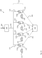
- Fig. 1A shows a charging system 100 according to the present invention, comprising a plurality 110 of charging stations 111, 112, 113, 114.
- the charging stations are each provided with a charging dispenser 111a, 112a, 113a, 114a that is adapted for charging an electric vehicle 121, 122, 123, 124.
- a charging system according to the invention may comprise tens or hundreds of charging stations, each with one or more charging dispensers.
- All charging dispensers are connected via a respective power cable 171, 172, 173, 174 to a common power line 170, which in turn is connected, via an overcurrent protection breaker 180 that is common to all charging dispensers of the system, to the electrical power grid 190.
- the breaker has a predefined maximum total current of 48 Ampere above which the breaker trips.
- each of the charging dispensers 111a, 112a, 113a, 114a is connected, via a charging cable as known in the art, to a corresponding electric vehicle 121, 122, 123, 124 for charging these vehicles.
- the charging dispensers are connected to a switch 160 via communications links 161, 162,163,164.
- each charging dispenser may transmit a message to all of the other dispensers via a broadcast message, and via which each charging dispenser may receive messages that have been transmitted by the other charging dispensers.
- a current budget has been assigned to each of the charging dispensers 111a, 112a, 113a, 124a in such a manner that a sum of the current budgets of all dispensers is less than the predefined maximum total current.
- each dispenser has been assigned a same current budget of 12 Ampere, obtained by dividing the predefined total maximum current of 48 Ampere by the total number of four charging dispensers in the system.
- the predefined total maximum current is defined by the breaker 180, it will be understood the total maximum current may additionally, or instead, be defined based on other factors, such a contract with an energy provider, availability of power from the grid 190, power cables used, and so on.
- Each of the EVs draws current from the charging dispenser it is connected to.
- the dispensers are adapted such that the total sum of current offered by the dispensers 111a, 112a,113a,114a, never exceeds the total current budget, in this manner substantially preventing the maximum current through the breaker 180 from exceeding the predefined maximum total current during normal operating circumstances.
- An example of steps for determining a current offered by each of the charging dispensers may be calculated will be provided below. These steps may also be denoted as an algorithm. Though many different algorithms may suffice, the same algorithm / steps should run on charging dispensers that can share current budget with each other, and each of these charging dispensers should receive the same data as input, e.g. for inputting into the algorithm, so that at each charging dispenser an offered current for said charging dispenser and offered currents for the other charging dispenser with which current can be shared, can be deterministically determined.
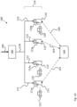
- Fig. 1B shows the charging system of Fig. 1A , in which no EV is connected to charging dispenser 113a.
- This charging dispenser 113a thus does not draw current for charging an EV, here indicated by showing the charging dispenser in solid black, as opposed to the other charging dispensers 111a, 112a and 114a which in Fig. 1B are used to charge EVs connected thereto.
- Each charging dispenser repeatedly checks the total current budget, and when appropriate, adapts its offered current, i.e. the current offered the charging dispenser for charging an EV connected thereto, if any.
- Each charging dispenser still has a current budget of 12 Ampere, so that the total current budget remains 48A.
- dispenser 113a does not use its current budget for charging an EV, its current budget can be shared among the dispensers to which an EV is connected for charging.
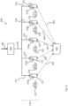
- Fig. 1C shows a charging system 100' according to the invention, in addition to comprising the same components as the charging system 100 of Fig 1A , further comprises an additional charging dispenser 115 that has been added after installation of the charging system 100 was completed. Regardless of how many dispensers the system 100'has, the predefined maximum total current that can be provided through power line 170 without tripping the breaker 180 remains 48 Ampere. In order to be able to add the additional charging dispenser 115a without risk of exceeding the predefined maximum total current, the current budget for the charging dispenser 115a is set to zero.
- the power cable 175 is connected between the charging dispenser 115a and the common power line 170, and the charging dispenser 115a is added to the local network via link 165 so that it may communicate with the other dispensers.
- the invention thus allows one or more additional charging dispenser to be added to a charging system that is already in operation, substantially without affecting operation of charging dispensers that were already present in the charging system before.
- electric vehicle 121 has finished charging, i.e. no longer draws current from charging dispenser 111a for charging.
- the total charging budget of 48 Ampere can be shared between the four other charging dispensers for charging the EVs connected thereto.
- Fig. 1D illustrates how the charging system of Fig. 1A can cope in case the communications link 162 (shown in Fig. 1A ) to charging dispenser 112a is out of order.
- the affected charging dispenser 112a is here shown using hatching to indicate a malfunction of it communications link.
- Each of the charging dispensers still has its assigned charging budget of 12 Ampere. However, due to the break in communication between dispenser 112a and the other dispensers 111a, 113a and 114a, no current budget can be shared between dispenser 112a and the other dispensers. Dispenser 112a however can continue to charging vehicle 122 connected thereto a current that is at most equal to the dispenser's current budget. The remaining dispenser which can still communicate with each other, can continue to share their charging budgets.
- Fig. 1E illustrates how the charging system of Fig. 1A can cope in case the power line 172 (shown in Fig. 1A ) to charging dispenser 112a is cut. In this case, charging dispenser 112a cannot provide any current for charging the EV 122 connected thereto. However, if communication between dispenser 112a and the other dispensers is still functioning, then the current budget that is assigned to dispenser 112a can still be communicated to the other charging dispensers and share it with the other dispensers. Thus, in Fig. 1A if the link 162 is still functioning, then dispensers 111a, 113a and 114a can calculate a total current budget of 48 Ampere and share this budget among dispensers 111a, 114a for charging an EV connected thereto.
- dispenser 112a If communications between dispenser 112a and the other dispensers has been disrupted, then the current budget of dispenser 112a is unknown to the other dispensers.
- Figs. 2A, 2B and 2C schematically show different embodiments of charging stations as may be used in the charging system of the invention.
- the charging station 111 shown in Fig. 2A comprises only a single dispenser 111a, and further comprises a memory storing instructions, and a processor connected to said memory, wherein the processor is configured, when executing the instructions for controlling the dispenser, in particular for controlling the dispenser to carry out steps i) - vi) of the independent claims.
- the charging station 117 of Fig. 2B comprises two charging dispensers 117a1, 117a2 in the same charging station.
- the charging station 117 further comprises a memory 117c storing instructions, and a processor 117b connected to said memory, wherein the processor is configured, when executing the instructions for controlling both of the dispensers 117a1, 117a2, in particular for controlling each of these dispensers to carry out steps i) - vi) of the independent claims.
- the charging station of 118 of Fig. 2C also comprises two charging dispensers 118a2, 118a2in the same charging station.
- each dispenser is provided with its own memory 118b1, 118b2 and processor 118c2,11cb, separate from the memory and processor of the other charging dispenser.
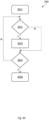
- Fig.3 shows a flow chart of steps that may be executed by each dispenser of a charging system of the present invention, in order to determine the offered current for one or more charging dispensers of said system. These steps together form an algorithm.
- the charging dispenser executing the algorithm is denoted as the local dispenser, and where appropriate any other charging dispenser of the system is denoted non-local charging dispenser.
- the local dispenser checks whether a requested charging current of a vehicle that is connected to the local dispenser is zero. If no electric vehicle is connected to the charging dispenser, or optionally, if an electric vehicle that is connected to the charging dispenser is not authorized to charge at said dispenser, then the requested charging current is considered to be zero. If the requested charging current for said local dispenser is zero or considered to be zero, then the offered current for the local dispenser is set to zero in step 380. Otherwise, in step 320 based on the messages that were received from charging dispensers in the network and accepted, the local dispenser generates a list of charging dispensers, wherein the local dispenser is also part of the list.
- next step 330 of checking whether a unidirectional network problem in communication between the local dispenser and any of the other dispensers from which messages were received and accepted is detected. For instance, a unidirectional network problem may be detected if it is found that the local charging dispenser can receive messages form the other dispensers, but is unable to transmit message via the network to other dispensers.
- step 330 If in optional step 330 such a unidirectional network problem is detected, then the offered current for the local dispenser is set to be equal to the local dispenser's current budget. Otherwise, or if step 330 is omitted altogether, then in step 340 it is checked whether the total current budget is greater than the predefined maximum total current. If so, then the offered current for the local dispenser is set to zero in step 380, to prevent that current drawn by the system from exceeding the predefined maximum total current. Otherwise, in step 350, the list is sorted to generate an ordered list. It is noted that an identical ordered list is typically generated not just by the local dispenser, but also by each dispenser from which the local dispenser received a message that was accepted by the local dispenser.
- the sorting order may be based for instance on the charging output value, and/or on factors such as a dispenser ID or amount of time a charging dispenser has been continuously charging, as may be included in messages that conform to the predetermined specification.
- the predetermined specification typically comprises a version number of the specification used and/or a version of firmware that is active on the charging dispenser that sent the message.
- step 360 a first traversal of the ordered list of charging dispensers is carried out in order, to distribute all or part of the total current budget in such a manner among the charging dispensers to ensure that an offered current for the charging dispensers can at least be equal to a minimum charging current with which the some or all of the dispensers in the ordered list can charge the EV connected thereto.
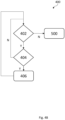
- Fig. 4A shows a flow chart of steps that may be carried out as substeps of step 360.
- any remaining budget of the total current budget can be distributed among the candidate offered currents that are associated with the charging dispensers in the ordered list. An example of how this may be done is described with reference to Fig. 4B .
- step 500 the local dispenser sets its offered current to be equal to the candidate offered current for the local dispenser.
- Fig. 4A shows a flow chart of steps that may be carried out as substeps of step 360 of Fig. 3 .
- step 361 the candidate offered currents that are associated with each dispenser in the list are initially set to zero.
- step 362 it is checked whether, for the charging dispenser, the total current budget is greater than the minimum charging current associated with said charging dispenser. If so, then in step 363, then the candidate offered current is set to said minimum charging current and the minimum charging current is subtracted from the total current budget.
- step 363 it is checked whether the entire ordered list has been traversed, If so, then the first traversal of the list is completed and next step 400 step may carried out. If tin step 364 it is determined that the list has not been traversed in its entirety, then the step 362 is proceeded with using the next charging dispenser in the ordered list.
- Fig. 4B shows a flow chart of steps that may be carried out as substeps of step 400.
- step 402 it is checked whether while the total current budget remaining is greater than a charging current increment associated with any of the charging dispensers in the list. If this is not the case, the step 500 of Fig. 3 is proceeded with. Otherwise, a further traversal of the ordered list is carried out.
- step 404 it is checked whether, for the charging dispenser, the total current budget is greater than the charging current increment associated with said charging dispenser and a sum of the charging current increment and the candidate offered current is less than a maximum charging current. If this is the case, then in step 406 the charging current increment is added to the candidate offered current and the charging current increment is subtracted from the total current budget. If this is not the case, or after step 406 has completed, step 402 is proceeded with using the next charging dispenser in the ordered list.
- the invention relates to a system for charging electric vehicles, said system comprising a plurality of charging stations which each comprise one or more charging dispensers that are connected to a common power line, wherein each of said charging dispensers has a current budget assigned thereto, wherein the sum of said current budgets is greater than zero and less than a predefined maximum total current that the system is allowed draw from the power line, wherein the charging dispensers are in communication with each other such that at each charging dispenser a total current budget can be calculated as a sum of all current budgets, and such that at each charging dispenser it can be determined what share of this total current budget is available to the dispenser for charging an electric vehicle connected thereto.
- Dispensers can be added to the system or removed therefrom, substantially without affecting regular operation of the other dispensers.
Landscapes
- Engineering & Computer Science (AREA)
- Power Engineering (AREA)
- Transportation (AREA)
- Mechanical Engineering (AREA)
- Charge And Discharge Circuits For Batteries Or The Like (AREA)
- Electric Propulsion And Braking For Vehicles (AREA)
Applications Claiming Priority (1)
| Application Number | Priority Date | Filing Date | Title |
|---|---|---|---|
| NL2035029A NL2035029B1 (en) | 2023-06-07 | 2023-06-07 | System for charging electric vehicles, a charging dispenser, and method for modifying said system |
Publications (1)
| Publication Number | Publication Date |
|---|---|
| EP4474209A1 true EP4474209A1 (fr) | 2024-12-11 |
Family
ID=87280371
Family Applications (1)
| Application Number | Title | Priority Date | Filing Date |
|---|---|---|---|
| EP24179656.4A Pending EP4474209A1 (fr) | 2023-06-07 | 2024-06-03 | Système de charge de véhicules électriques, distributeur de charge et procédé de modification dudit système |
Country Status (3)
| Country | Link |
|---|---|
| US (1) | US20240408992A1 (fr) |
| EP (1) | EP4474209A1 (fr) |
| NL (1) | NL2035029B1 (fr) |
Citations (5)
| Publication number | Priority date | Publication date | Assignee | Title |
|---|---|---|---|---|
| WO2012149965A1 (fr) | 2011-05-04 | 2012-11-08 | Siemens Aktiengesellschaft | Procédé et dispositif de fourniture d'énergie électrique |
| US20150165917A1 (en) * | 2011-12-29 | 2015-06-18 | Abb B.V. | Method, system and charger for charging a battery of an electric vehicle |
| DE102018209761A1 (de) * | 2018-06-18 | 2019-12-19 | Bayerische Motoren Werke Aktiengesellschaft | Verfahren zur Konfiguration eines Ladesystems und Ladesystem zum Laden des elektrischen Energiespeichers eines Fahrzeugs |
| WO2022097555A1 (fr) * | 2020-11-06 | 2022-05-12 | パナソニックIpマネジメント株式会社 | Dispositif de commande de charge, système de charge, procédé de commande de charge et programme |
| US20220314834A1 (en) | 2019-12-19 | 2022-10-06 | EVAR Inc. | Power supply method of charger for electric vehicle |
-
2023
- 2023-06-07 NL NL2035029A patent/NL2035029B1/en active
-
2024
- 2024-06-03 EP EP24179656.4A patent/EP4474209A1/fr active Pending
- 2024-06-06 US US18/735,573 patent/US20240408992A1/en active Pending
Patent Citations (6)
| Publication number | Priority date | Publication date | Assignee | Title |
|---|---|---|---|---|
| WO2012149965A1 (fr) | 2011-05-04 | 2012-11-08 | Siemens Aktiengesellschaft | Procédé et dispositif de fourniture d'énergie électrique |
| US20140084874A1 (en) * | 2011-05-04 | 2014-03-27 | Siemens Aktiengesellschaft | Method and apparatus for providing electrical energy |
| US20150165917A1 (en) * | 2011-12-29 | 2015-06-18 | Abb B.V. | Method, system and charger for charging a battery of an electric vehicle |
| DE102018209761A1 (de) * | 2018-06-18 | 2019-12-19 | Bayerische Motoren Werke Aktiengesellschaft | Verfahren zur Konfiguration eines Ladesystems und Ladesystem zum Laden des elektrischen Energiespeichers eines Fahrzeugs |
| US20220314834A1 (en) | 2019-12-19 | 2022-10-06 | EVAR Inc. | Power supply method of charger for electric vehicle |
| WO2022097555A1 (fr) * | 2020-11-06 | 2022-05-12 | パナソニックIpマネジメント株式会社 | Dispositif de commande de charge, système de charge, procédé de commande de charge et programme |
Also Published As
| Publication number | Publication date |
|---|---|
| US20240408992A1 (en) | 2024-12-12 |
| NL2035029B1 (en) | 2024-12-19 |
Similar Documents
| Publication | Publication Date | Title |
|---|---|---|
| US20160250942A1 (en) | Charging state management method, charging state management device, and program | |
| US8358102B2 (en) | System, charging device, and method of charging a power storage device | |
| US9209629B2 (en) | Charge-discharge control device, charge-discharge control system, and computer program product | |
| US9184601B2 (en) | Charge-discharge control device, charge-discharge monitoring device, charge-discharge control system, and computer program product | |
| US8384359B2 (en) | System, charging device, and method of charging a power storage device | |
| Esmaili et al. | Optimal charging of plug‐in electric vehicles observing power grid constraints | |
| EP3016238A1 (fr) | Procédé de gestion d'état de charge, dispositif de gestion d'état de charge et programme | |
| JP2013519354A (ja) | 電気車両の協調充電のための方法およびシステム | |
| US20220314831A1 (en) | Grid system, power transferring and receiving method, and storage medium | |
| JP2022098972A (ja) | サーバ、電力管理方法 | |
| CN115195476B (zh) | 车辆能量管理方法、装置、设备、可读存储介质及车辆 | |
| US20160164312A1 (en) | Power management system and power management method | |
| JP2024029489A (ja) | 充放電制御システム及び充放電制御プログラム | |
| CN117955140A (zh) | 功率分配方法、装置、储能电站及存储介质 | |
| EP4474209A1 (fr) | Système de charge de véhicules électriques, distributeur de charge et procédé de modification dudit système | |
| RU2608181C2 (ru) | Способ и устройство для контроля точки подвода энергии в сети энергосбережения | |
| CN106058899A (zh) | 储能系统的监控系统 | |
| JP2024022206A (ja) | 電力システム、制御装置、および電力システムの制御方法 | |
| Golshani et al. | PHEVs contribution to the self-healing process of distribution systems | |
| Jayashree et al. | Impact of hybrid electric vehicle penetration and its challenges on distribution system | |
| CN114709890A (zh) | 一种多机并联系统中电池电量的均衡方法及装置 | |
| KR20210044930A (ko) | 정전수용가의 전기공급 장치 및 그 방법 | |
| EP4641866A1 (fr) | Générateur de commande d'équilibre | |
| Szűcs et al. | Implementation and Simulation of a Load Balancing Solution for Electric Vehicle Charge Points | |
| JP7804521B2 (ja) | 充電装置、充電システム、制御方法及び制御プログラム |
Legal Events
| Date | Code | Title | Description |
|---|---|---|---|
| PUAI | Public reference made under article 153(3) epc to a published international application that has entered the european phase |
Free format text: ORIGINAL CODE: 0009012 |
|
| STAA | Information on the status of an ep patent application or granted ep patent |
Free format text: STATUS: THE APPLICATION HAS BEEN PUBLISHED |
|
| AK | Designated contracting states |
Kind code of ref document: A1 Designated state(s): AL AT BE BG CH CY CZ DE DK EE ES FI FR GB GR HR HU IE IS IT LI LT LU LV MC ME MK MT NL NO PL PT RO RS SE SI SK SM TR |
|
| STAA | Information on the status of an ep patent application or granted ep patent |
Free format text: STATUS: REQUEST FOR EXAMINATION WAS MADE |
|
| 17P | Request for examination filed |
Effective date: 20250611 |