EP4474230A1 - Dispositif d'actionnement pour un vehicule - Google Patents
Dispositif d'actionnement pour un vehicule Download PDFInfo
- Publication number
- EP4474230A1 EP4474230A1 EP23382569.4A EP23382569A EP4474230A1 EP 4474230 A1 EP4474230 A1 EP 4474230A1 EP 23382569 A EP23382569 A EP 23382569A EP 4474230 A1 EP4474230 A1 EP 4474230A1
- Authority
- EP
- European Patent Office
- Prior art keywords
- elastic means
- rocker
- actuation device
- pushing element
- target
- Prior art date
- Legal status (The legal status is an assumption and is not a legal conclusion. Google has not performed a legal analysis and makes no representation as to the accuracy of the status listed.)
- Granted
Links
Images





Classifications
-
- B—PERFORMING OPERATIONS; TRANSPORTING
- B60—VEHICLES IN GENERAL
- B60T—VEHICLE BRAKE CONTROL SYSTEMS OR PARTS THEREOF; BRAKE CONTROL SYSTEMS OR PARTS THEREOF, IN GENERAL; ARRANGEMENT OF BRAKING ELEMENTS ON VEHICLES IN GENERAL; PORTABLE DEVICES FOR PREVENTING UNWANTED MOVEMENT OF VEHICLES; VEHICLE MODIFICATIONS TO FACILITATE COOLING OF BRAKES
- B60T11/00—Transmitting braking action from initiating means to ultimate brake actuator without power assistance or drive or where such assistance or drive is irrelevant
- B60T11/04—Transmitting braking action from initiating means to ultimate brake actuator without power assistance or drive or where such assistance or drive is irrelevant transmitting mechanically
- B60T11/06—Equalising arrangements
-
- B—PERFORMING OPERATIONS; TRANSPORTING
- B60—VEHICLES IN GENERAL
- B60T—VEHICLE BRAKE CONTROL SYSTEMS OR PARTS THEREOF; BRAKE CONTROL SYSTEMS OR PARTS THEREOF, IN GENERAL; ARRANGEMENT OF BRAKING ELEMENTS ON VEHICLES IN GENERAL; PORTABLE DEVICES FOR PREVENTING UNWANTED MOVEMENT OF VEHICLES; VEHICLE MODIFICATIONS TO FACILITATE COOLING OF BRAKES
- B60T11/00—Transmitting braking action from initiating means to ultimate brake actuator without power assistance or drive or where such assistance or drive is irrelevant
- B60T11/10—Transmitting braking action from initiating means to ultimate brake actuator without power assistance or drive or where such assistance or drive is irrelevant transmitting by fluid means, e.g. hydraulic
- B60T11/16—Master control, e.g. master cylinders
- B60T11/18—Connection thereof to initiating means
-
- B—PERFORMING OPERATIONS; TRANSPORTING
- B60—VEHICLES IN GENERAL
- B60T—VEHICLE BRAKE CONTROL SYSTEMS OR PARTS THEREOF; BRAKE CONTROL SYSTEMS OR PARTS THEREOF, IN GENERAL; ARRANGEMENT OF BRAKING ELEMENTS ON VEHICLES IN GENERAL; PORTABLE DEVICES FOR PREVENTING UNWANTED MOVEMENT OF VEHICLES; VEHICLE MODIFICATIONS TO FACILITATE COOLING OF BRAKES
- B60T17/00—Component parts, details, or accessories of power brake systems not covered by groups B60T8/00, B60T13/00 or B60T15/00, or presenting other characteristic features
- B60T17/18—Safety devices; Monitoring
- B60T17/22—Devices for monitoring or checking brake systems; Signal devices
-
- B—PERFORMING OPERATIONS; TRANSPORTING
- B60—VEHICLES IN GENERAL
- B60T—VEHICLE BRAKE CONTROL SYSTEMS OR PARTS THEREOF; BRAKE CONTROL SYSTEMS OR PARTS THEREOF, IN GENERAL; ARRANGEMENT OF BRAKING ELEMENTS ON VEHICLES IN GENERAL; PORTABLE DEVICES FOR PREVENTING UNWANTED MOVEMENT OF VEHICLES; VEHICLE MODIFICATIONS TO FACILITATE COOLING OF BRAKES
- B60T7/00—Brake-action initiating means
- B60T7/02—Brake-action initiating means for personal initiation
- B60T7/04—Brake-action initiating means for personal initiation foot actuated
- B60T7/06—Disposition of pedal
-
- B—PERFORMING OPERATIONS; TRANSPORTING
- B60—VEHICLES IN GENERAL
- B60T—VEHICLE BRAKE CONTROL SYSTEMS OR PARTS THEREOF; BRAKE CONTROL SYSTEMS OR PARTS THEREOF, IN GENERAL; ARRANGEMENT OF BRAKING ELEMENTS ON VEHICLES IN GENERAL; PORTABLE DEVICES FOR PREVENTING UNWANTED MOVEMENT OF VEHICLES; VEHICLE MODIFICATIONS TO FACILITATE COOLING OF BRAKES
- B60T7/00—Brake-action initiating means
- B60T7/02—Brake-action initiating means for personal initiation
- B60T7/08—Brake-action initiating means for personal initiation hand actuated
- B60T7/10—Disposition of hand control
-
- G—PHYSICS
- G05—CONTROLLING; REGULATING
- G05G—CONTROL DEVICES OR SYSTEMS INSOFAR AS CHARACTERISED BY MECHANICAL FEATURES ONLY
- G05G1/00—Controlling members, e.g. knobs or handles; Assemblies or arrangements thereof; Indicating position of controlling members
- G05G1/30—Controlling members actuated by foot
- G05G1/38—Controlling members actuated by foot comprising means to continuously detect pedal position
-
- B—PERFORMING OPERATIONS; TRANSPORTING
- B60—VEHICLES IN GENERAL
- B60T—VEHICLE BRAKE CONTROL SYSTEMS OR PARTS THEREOF; BRAKE CONTROL SYSTEMS OR PARTS THEREOF, IN GENERAL; ARRANGEMENT OF BRAKING ELEMENTS ON VEHICLES IN GENERAL; PORTABLE DEVICES FOR PREVENTING UNWANTED MOVEMENT OF VEHICLES; VEHICLE MODIFICATIONS TO FACILITATE COOLING OF BRAKES
- B60T2250/00—Monitoring, detecting, estimating vehicle conditions
- B60T2250/06—Sensor zero-point adjustment; Offset compensation
-
- G—PHYSICS
- G05—CONTROLLING; REGULATING
- G05G—CONTROL DEVICES OR SYSTEMS INSOFAR AS CHARACTERISED BY MECHANICAL FEATURES ONLY
- G05G1/00—Controlling members, e.g. knobs or handles; Assemblies or arrangements thereof; Indicating position of controlling members
- G05G1/30—Controlling members actuated by foot
- G05G1/42—Controlling members actuated by foot non-pivoting, e.g. sliding
-
- G—PHYSICS
- G05—CONTROLLING; REGULATING
- G05G—CONTROL DEVICES OR SYSTEMS INSOFAR AS CHARACTERISED BY MECHANICAL FEATURES ONLY
- G05G5/00—Means for preventing, limiting or returning the movements of parts of a control mechanism, e.g. locking controlling member
- G05G5/03—Means for enhancing the operator's awareness of arrival of the controlling member at a command or datum position; Providing feel, e.g. means for creating a counterforce
Definitions
- the present invention relates to an actuation device for a vehicle, a vehicle incorporating said actuation device, and a method for detecting the failure of an elastic means applied in said actuation device.
- Actuation devices for vehicles in particular foot-operated actuation devices, in which the driver's action is measured by means of sensors that measure the position of the actuation device and/or the force with which the actuation device is being actuated at all times, are known.
- a control unit is in charge of interpreting the information from the sensors so as to act on the corresponding system, such that the driver's action on the actuation device is transmitted to the corresponding system without there having to be a direct mechanical connection between the actuation device and the system.
- braking systems known as "brake by wire” are known in which the braking actuation device is equipped with sensors and does not act directly on the braking system, but rather the sensors of the actuation device detect the position and/or the force with which the actuation device is being acted on at all times, and a control unit is in charge of interpreting the information from the sensors so as to act on the braking system.
- Braking actuation devices of this type require an ASIL D security level, which makes it necessary to combine at least two different types of sensors, such that a redundant measurement of the action on the braking actuation device is obtained.
- ASIL D security level which makes it necessary to combine at least two different types of sensors, such that a redundant measurement of the action on the braking actuation device is obtained.
- braking actuation devices of this type usually have, for the most part, three types of sensors: angular sensors, linear sensors, and/or force sensors.
- the object of the invention is to provide an actuation device for a vehicle, a vehicle incorporating said actuation device, and a method for detecting the failure of an elastic means applied in said actuation device, as defined in the claims.
- a first aspect of the invention relates to an actuation device for a vehicle.
- the actuation device comprises a pushing element that is displaced when a driver acts on the actuation device, a first elastic means and a second elastic means arranged in parallel, and a rocker.
- the pushing element When the pushing element is displaced, i.e., when a driver acts on the actuation device, the first elastic means and the second elastic means are compressed, exerting a force on the rocker, an incorrect operation of the first elastic means or of the second elastic means being detected when the rocker has an inclination other than a predetermined reference inclination.
- the first elastic means and the second elastic means form an elastic system exerting certain resistance to the driver's action on the actuation device such that the driver receives a suitable actuation sensation.
- Including a rocker on which the first elastic means and the second elastic means act, such that the inclination of said rocker reflects whether or not said elastic means work properly, makes it possible to detect a failure in the elastic system using a pair of linear sensors or an angular sensor which measures the inclination of said rocker, such that a failure of the elastic system can be detected without needing to use a force sensor.
- a second aspect of the invention relates to a vehicle incorporating an actuation device such as the one described in the first aspect of the invention.
- a third aspect of the invention relates to a method for detecting the failure of an elastic means in an actuation device such as the one described in the first aspect of the invention.
- the method for detecting the failure of an elastic means of an actuation device monitors the degree of inclination of the rocker such that if said degree of inclination differs from the predetermined degree of inclination, the failure of one of the elastic means is determined.
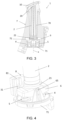
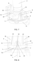
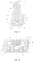
- Figures 1 to 14 show a preferred embodiment of the actuation device 1 according to the invention.
- Figures 3 to 5 show the actuation device 1 when in standby, i.e., when the driver does not act on the actuation device.
- Figures 6 to 8 show the actuation device 1 being actuated by the driver.
- Figures 11 to 14 show the actuation device, with the second elastic means 5 broken.
- the actuation device 1 is a foot-operated actuation device and can be of the pressure pad type, like the one shown in the preferred embodiment, a conventional pivotable pedal, or an organ-type pedal.
- the driver's action on the actuation device 1 is measured by means of sensors that measure the position of the actuation device, and a specific control unit or the central control unit of the vehicle is in charge of interpreting the information from the sensors so as to act on the corresponding system.
- the actuation device 1 is an electronic brake device, also known as a "brake by wire” device.
- the actuation device could be applied to be used as an accelerator or clutch.
- the actuation device 1 comprises a pushing element 2 that is displaced when a driver acts on the actuation device 1.
- the actuation device 1 comprises a plate 10, such that the driver acts with his/her foot on said plate 10.
- the pushing element 2 comprises a first end 20 coupled to the plate 10, such that when the driver acts on the plate 10 the pushing element 2 is displaced on an axis of displacement x.
- the plate can be coupled to the pushing element by means of an intermediate element.
- the actuation device 1 also comprises a first elastic means 4 and a second elastic means 5 arranged in parallel, and a rocker 6.
- the first elastic means 4 and the second elastic means 5 form an elastic system exerting certain resistance to the displacement of the pushing element 2 when the driver acts on the actuation device 1, such that the driver receives a suitable actuation sensation.
- the use of an elastic system to provide this opposition to the actuation of the actuation device 1 is also known as a "feel simulator".
- the actuation device 1 has a configuration such that it allows it to continue to be operative in the case of breakage of one of the elastic means 4, 5, such that although the driver may notice a change in the actuation sensation, he/she can continue acting on the actuation device 1 and therefore can continue to use the system associated with the actuation device 1.
- the rocker 6 comprises a support part 64, a first part 62 on a side of the support part 64 and a second part 63 on the other side of the support part 64.
- the first elastic means 4 exerts a force on the first part 62
- the second elastic means 5 exerts a force on the second part 63.
- only the other elastic means would exert a force on the rocker 6, obtaining an inclination of the rocker 6 other than the predetermined reference inclination.
- the support part 64 is arranged in the central part of the rocker 6, the first part 62 being a first half of the rocker 6 and the second part 63 being a second half of the rocker 6.
- the rocker 6 comprises in the support part 64 a semispherical protrusion 640 cooperating with a semispherical negative print of the actuating element 2.
- the displacement of the pushing element 2 compresses said first elastic means 4 and said second elastic means 5 to the same extent.
- the first elastic means 4 and the second elastic means 5 comprise substantially the same characteristics and are arranged such that the rocker 6 is arranged substantially perpendicular with respect to the axis of displacement x of the pushing element 2.
- the rocker 6 would be arranged at all times, i.e., both in standby (see Figure 5 ) and when the driver acts on the actuation device 1 (see Figure 8 ), perpendicular with respect to the axis of displacement x of the pushing element 2, and it can be considered that in this situation, the predetermined reference inclination of the rocker 6 would be 0°, making it possible to determine the breakage of the first elastic means 4 or of the second elastic means 5 if the rocker 6 was not arranged perpendicular (see Figure 14 ) with respect to the axis of displacement x of the pushing element 2, i.e., if the inclination of the rocker 6 were to differ from 0°, in standby and/or when the driver acts on the actuation device 1.
- the predetermined reference inclination could be one other than 0°, i.e., during the normal operation of the first elastic means and of the second elastic means in standby and/or when actuated by the driver, the rocker may not be arranged perpendicular with respect to the axis of displacement x of the pushing element.
- the actuation device 1 comprises a first target 30 and a second target 31 coupled to the rocker 6, a first linear sensor configured for measuring the displacement of the first target 30, and a second linear sensor configured for measuring the displacement of the second target 31, the inclination of the rocker 6 being determined depending on the measurement of said first linear sensor and said second linear sensor.
- the first linear sensor is an inductive sensor
- the second linear sensor is a magnetic linear sensor, the first target 30 being a metallic sheet and the second target 31 being a magnet.
- the rocker 6 comprises a first pivot 66 in which the first target 30 is pivotably coupled, and a second pivot 67 in which the second target 31 is pivotably coupled.
- the actuation device 1 also comprises an electronic assembly 8 comprising an electronic board in which the first linear sensor and the second linear sensor are arranged, a first guide channel 80 in which the first target 30 is movably housed, and a second guide channel 81 in which the second target 31 is movably housed.
- the actuation device could comprise different guiding means for the first target and the second target, or even dispense with guiding means provided that it is ensured that the reading of the sensors is suitable.
- the actuation device may comprise an angular sensor for measuring the inclination of the rocker.
- the rocker 6 is arranged between the pushing element 2 and the first elastic means 4 and the second elastic means 5, as shown in the figures of the preferred embodiment of the invention, with the pushing element 2 being arranged supported on the outer face 61 of the support part 64 of the rocker 6, the inner face of the first part 62 of the rocker 6 being supported on the first elastic means 4, and the inner face of the second part 63 of the rocker 6 being supported on the second elastic means 5. Therefore, the displacement of the pushing element 2 pushes the rocker 6, which is also displaced along the axis of displacement x of the pushing element 2, the rocker 6 compressing the first elastic means 4 and the second elastic means 5.
- the displacement of the pushing element 2 is determined, i.e., the driver's action on the actuation device 1 is determined depending on the displacement of the rocker 6. Therefore, by using only two linear sensors it would be possible both to detect the failure of one of the elastic means 4, 5 and to determine the driver's action on the actuation device 1, such that if said linear sensors are based on different technologies, for example one of them is an inductive sensor and the other one is a magnetic sensor, the ASIL D standard would also be met in the event that the actuation device 1 is used for applying a "brake by wire".
- FIG. 12 shows the arrangement of the rocker 6 of the preferred embodiment with the second elastic means 5 broken.
- the pressure exerted by the first elastic means 4 on the rocker 6 causes the outer face 60 of the first part 62 of the rocker 6 to abut with the pushing element 2, exerting pressure thereon and causing said pushing element 2 to have a tendency for the standby position exerting opposition against the driver's action on the actuation element 1 which will be less than that resulting from both elastic means 4, 5 when working properly.
- the actuation device 1 comprises a cover 71, shown in detail in Figure 10 , comprising a base 710 and a pair of arms 711 extending perpendicularly from said base 710, each arm 711 comprising a groove 712.
- the rocker 6 comprises a pair of coupling shafts 65, the coupling shafts 65 of the rocker 6 being movably coupled in the grooves 712 of the arms 711 of the cover 71.
- the rocker 6 is thereby arranged coupled to the cover 71 in a movable manner with respect to the axis of displacement x of the pushing element 2, and in a pivotable manner such that in the case of breakage of the first elastic means 4 or the second elastic means 5 the rocker 6 can pivot with respect to said axis of displacement x of the pushing element 2.
- the first elastic means 4 and the second elastic means 5 are arranged between the rocker 6 and the base 710 of the cover 71.
- the base 710 comprises a retaining element 713 for the first elastic means 4 and a retaining element 713 for the second elastic means 5, such that said retaining elements 713 fix the first elastic means 4 and the second elastic means 5 with respect to the base 710.
- the first elastic means 4 consists of a single spring and the second elastic means consists of a single spring.
- the actuation device 1 comprises a main support 7 comprising a guide housing 70 in which the pushing element 2 is movably housed, and a main housing 72 communicated with the guide housing 70 in which the rocker 6, the first elastic means 4, and the second elastic means 5 are arranged, the cover 71 being fixed to said main support 7, covering an opening of the main housing 72.
- the rocker can be arranged between a fixed base and the first elastic means and the second elastic means, the pushing element acting on a first end of the first elastic means and on a first end of the second elastic means, a second end of the first elastic means being supported on a first face of the first part of the rocker, a second end of the second elastic means being supported on the first face of the second part of the rocker, and a second face (opposite the first face) of the support part of the rocker being supported on the fixed base.
- Figures 15 to 17 show an alternative embodiment of the actuation device of the invention.
- Said alternative embodiment differs from the preferred embodiment in the configuration of the first elastic means 4 and the second elastic means 5.
- the remaining features are similar to those of the preferred embodiment and it is therefore not considered necessary to describe them again.
- both the first elastic means 4 and the second elastic means 5 comprise a main spring 40, 50 and a secondary spring 41, 51 connected in series, the secondary springs 41, 51 comprising an elastic constant less than that of the main springs 40, 50, the secondary springs 41, 51 being configured to prestress the rocker 6 when the actuation device 1 is not actuated by the driver.
- both the first elastic means 4 and the second elastic means 5 also comprise a support 42, 52.
- both the first elastic means 4 and the second elastic means 5 are arranged as follows between the base 710 and the rocker 6: the first end 401, 501 of the main spring 40, 50 is arranged supported at the base 710, the support 42, 52 is arranged supported at the second end 400, 500 of the main spring 40, 50, a first end 411, 511 of the secondary spring 41, 51 is housed in the support 42, 52, and a second end 410, 510 of the secondary spring 41,51 is supported against the rocker 6.
- a second aspect of the invention relates to a vehicle comprising at least one actuation device 1 like the one described above.
- a third aspect of the invention relates to a method for detecting the failure of an elastic means 4, 5 of an actuation device 1 like the one described above.
- the degree of inclination of the rocker 6 is monitored such that if said degree of inclination differs from the predetermined degree of inclination, the failure of one of the elastic means 4, 5 is determined.
Landscapes
- Engineering & Computer Science (AREA)
- Transportation (AREA)
- Mechanical Engineering (AREA)
- Physics & Mathematics (AREA)
- General Physics & Mathematics (AREA)
- Automation & Control Theory (AREA)
- Mechanical Control Devices (AREA)
- Valves And Accessory Devices For Braking Systems (AREA)
Priority Applications (1)
| Application Number | Priority Date | Filing Date | Title |
|---|---|---|---|
| EP23382569.4A EP4474230B1 (fr) | 2023-06-09 | 2023-06-09 | Dispositif d'actionnement pour un vehicule |
Applications Claiming Priority (1)
| Application Number | Priority Date | Filing Date | Title |
|---|---|---|---|
| EP23382569.4A EP4474230B1 (fr) | 2023-06-09 | 2023-06-09 | Dispositif d'actionnement pour un vehicule |
Publications (2)
| Publication Number | Publication Date |
|---|---|
| EP4474230A1 true EP4474230A1 (fr) | 2024-12-11 |
| EP4474230B1 EP4474230B1 (fr) | 2026-01-21 |
Family
ID=87378171
Family Applications (1)
| Application Number | Title | Priority Date | Filing Date |
|---|---|---|---|
| EP23382569.4A Active EP4474230B1 (fr) | 2023-06-09 | 2023-06-09 | Dispositif d'actionnement pour un vehicule |
Country Status (1)
| Country | Link |
|---|---|
| EP (1) | EP4474230B1 (fr) |
Citations (4)
| Publication number | Priority date | Publication date | Assignee | Title |
|---|---|---|---|---|
| JP2004050952A (ja) * | 2002-07-19 | 2004-02-19 | Kubota Corp | 乗用作業車の制動構造 |
| EP1731392A1 (fr) * | 2005-05-18 | 2006-12-13 | Kabushiki Kaisha Toyota Jidoshokki | Frein de stationnement |
| JP2016078612A (ja) * | 2014-10-16 | 2016-05-16 | ヤンマー株式会社 | 作業車両 |
| US20210213925A1 (en) * | 2018-05-22 | 2021-07-15 | Yanmar Power Technology Co., Ltd. | Brake System for Work Vehicles |
-
2023
- 2023-06-09 EP EP23382569.4A patent/EP4474230B1/fr active Active
Patent Citations (4)
| Publication number | Priority date | Publication date | Assignee | Title |
|---|---|---|---|---|
| JP2004050952A (ja) * | 2002-07-19 | 2004-02-19 | Kubota Corp | 乗用作業車の制動構造 |
| EP1731392A1 (fr) * | 2005-05-18 | 2006-12-13 | Kabushiki Kaisha Toyota Jidoshokki | Frein de stationnement |
| JP2016078612A (ja) * | 2014-10-16 | 2016-05-16 | ヤンマー株式会社 | 作業車両 |
| US20210213925A1 (en) * | 2018-05-22 | 2021-07-15 | Yanmar Power Technology Co., Ltd. | Brake System for Work Vehicles |
Also Published As
| Publication number | Publication date |
|---|---|
| EP4474230B1 (fr) | 2026-01-21 |
Similar Documents
| Publication | Publication Date | Title |
|---|---|---|
| US4888997A (en) | Control input device | |
| US10994707B2 (en) | Position and force sensor assembly for vehicle brake pedal | |
| EP2775373A1 (fr) | Dispositif pour détecter l'amplitude de la man uvre d'une pédale | |
| EP1892435B1 (fr) | Système de détection | |
| EP2003434B1 (fr) | Dispositif d'actionnement équipé d'un capteur de charge | |
| US20190163226A1 (en) | Pedal device | |
| EP1577184B1 (fr) | Appareil de freinage d'un véhicule | |
| EP2615519A1 (fr) | Appareil de détection d'amplitude de manipulation de pédale | |
| EP1394650A1 (fr) | Détecteur d'angle de rotation | |
| EP2741165A1 (fr) | Détecteur d'actionnement à pédale | |
| JP2005132216A (ja) | 踏力センサとそれを用いたペダル踏力検出装置 | |
| US20230302897A1 (en) | Device for detecting a driver demand | |
| JP2015212692A (ja) | 触覚又は聴覚フィードバックを利用するノギス測定力インジケータ | |
| EP4474230A1 (fr) | Dispositif d'actionnement pour un vehicule | |
| EP1733179A2 (fr) | Ensemble de conduite a commande electrique pourvu d'une jauge de contrainte | |
| KR102864253B1 (ko) | 이중 모드 감지 조이스틱 어셈블리 | |
| EP4155487A1 (fr) | Dispositif de détection et système de détection permettant d'activer au moins une fonction d'un appareil et appareil comprenant le système de détection | |
| JP5698502B2 (ja) | 力センサーを備えるアクチュエータ装置 | |
| WO2005098563A2 (fr) | Systeme de commandes electriques de conduite automobile a capteur de mesure de force | |
| US11091032B2 (en) | Pedal for a motor vehicle | |
| CN118457514A (zh) | 踏板总成、制动系统和车辆 | |
| JP4622818B2 (ja) | ブレーキ踏力検出装置およびブレーキ踏力検出方法 | |
| JP2022117118A (ja) | ペダルの踏力検出機構 | |
| JP7769550B2 (ja) | 車載用表示操作装置 | |
| CN120481941A (zh) | 一种踏板总成、制动系统和车辆 |
Legal Events
| Date | Code | Title | Description |
|---|---|---|---|
| PUAI | Public reference made under article 153(3) epc to a published international application that has entered the european phase |
Free format text: ORIGINAL CODE: 0009012 |
|
| STAA | Information on the status of an ep patent application or granted ep patent |
Free format text: STATUS: THE APPLICATION HAS BEEN PUBLISHED |
|
| AK | Designated contracting states |
Kind code of ref document: A1 Designated state(s): AL AT BE BG CH CY CZ DE DK EE ES FI FR GB GR HR HU IE IS IT LI LT LU LV MC ME MK MT NL NO PL PT RO RS SE SI SK SM TR |
|
| STAA | Information on the status of an ep patent application or granted ep patent |
Free format text: STATUS: REQUEST FOR EXAMINATION WAS MADE |
|
| 17P | Request for examination filed |
Effective date: 20250611 |
|
| GRAP | Despatch of communication of intention to grant a patent |
Free format text: ORIGINAL CODE: EPIDOSNIGR1 |
|
| STAA | Information on the status of an ep patent application or granted ep patent |
Free format text: STATUS: GRANT OF PATENT IS INTENDED |
|
| GRAS | Grant fee paid |
Free format text: ORIGINAL CODE: EPIDOSNIGR3 |
|
| INTG | Intention to grant announced |
Effective date: 20251110 |
|
| GRAA | (expected) grant |
Free format text: ORIGINAL CODE: 0009210 |
|
| STAA | Information on the status of an ep patent application or granted ep patent |
Free format text: STATUS: THE PATENT HAS BEEN GRANTED |
|
| AK | Designated contracting states |
Kind code of ref document: B1 Designated state(s): AL AT BE BG CH CY CZ DE DK EE ES FI FR GB GR HR HU IE IS IT LI LT LU LV MC ME MK MT NL NO PL PT RO RS SE SI SK SM TR |
|
| REG | Reference to a national code |
Ref country code: CH Ref legal event code: F10 Free format text: ST27 STATUS EVENT CODE: U-0-0-F10-F00 (AS PROVIDED BY THE NATIONAL OFFICE) Effective date: 20260121 |
|
| REG | Reference to a national code |
Ref country code: DE Ref legal event code: R096 Ref document number: 602023011002 Country of ref document: DE |
|
| REG | Reference to a national code |
Ref country code: IE Ref legal event code: FG4D |