EP4474538A1 - Dispositif d'étirage, poste de filage et procédé - Google Patents
Dispositif d'étirage, poste de filage et procédé Download PDFInfo
- Publication number
- EP4474538A1 EP4474538A1 EP24180095.2A EP24180095A EP4474538A1 EP 4474538 A1 EP4474538 A1 EP 4474538A1 EP 24180095 A EP24180095 A EP 24180095A EP 4474538 A1 EP4474538 A1 EP 4474538A1
- Authority
- EP
- European Patent Office
- Prior art keywords
- thread
- drafting device
- roller
- rollers
- designed
- Prior art date
- Legal status (The legal status is an assumption and is not a legal conclusion. Google has not performed a legal analysis and makes no representation as to the accuracy of the status listed.)
- Pending
Links
Images


Classifications
-
- D—TEXTILES; PAPER
- D01—NATURAL OR MAN-MADE THREADS OR FIBRES; SPINNING
- D01H—SPINNING OR TWISTING
- D01H5/00—Drafting machines or arrangements ; Threading of roving into drafting machine
- D01H5/18—Drafting machines or arrangements without fallers or like pinned bars
- D01H5/28—Drafting machines or arrangements without fallers or like pinned bars in which fibres are controlled by inserting twist during drafting
-
- D—TEXTILES; PAPER
- D01—NATURAL OR MAN-MADE THREADS OR FIBRES; SPINNING
- D01H—SPINNING OR TWISTING
- D01H4/00—Open-end spinning machines or arrangements for imparting twist to independently moving fibres separated from slivers; Piecing arrangements therefor; Covering endless core threads with fibres by open-end spinning techniques
- D01H4/48—Piecing arrangements; Control therefor
-
- D—TEXTILES; PAPER
- D01—NATURAL OR MAN-MADE THREADS OR FIBRES; SPINNING
- D01H—SPINNING OR TWISTING
- D01H13/00—Other common constructional features, details or accessories
- D01H13/32—Counting, measuring, recording or registering devices
-
- D—TEXTILES; PAPER
- D01—NATURAL OR MAN-MADE THREADS OR FIBRES; SPINNING
- D01H—SPINNING OR TWISTING
- D01H4/00—Open-end spinning machines or arrangements for imparting twist to independently moving fibres separated from slivers; Piecing arrangements therefor; Covering endless core threads with fibres by open-end spinning techniques
- D01H4/02—Open-end spinning machines or arrangements for imparting twist to independently moving fibres separated from slivers; Piecing arrangements therefor; Covering endless core threads with fibres by open-end spinning techniques imparting twist by a fluid, e.g. air vortex
-
- D—TEXTILES; PAPER
- D01—NATURAL OR MAN-MADE THREADS OR FIBRES; SPINNING
- D01H—SPINNING OR TWISTING
- D01H5/00—Drafting machines or arrangements ; Threading of roving into drafting machine
- D01H5/18—Drafting machines or arrangements without fallers or like pinned bars
- D01H5/32—Regulating or varying draft
-
- D—TEXTILES; PAPER
- D01—NATURAL OR MAN-MADE THREADS OR FIBRES; SPINNING
- D01H—SPINNING OR TWISTING
- D01H5/00—Drafting machines or arrangements ; Threading of roving into drafting machine
- D01H5/18—Drafting machines or arrangements without fallers or like pinned bars
- D01H5/60—Arrangements maintaining drafting elements free of fibre accumulations
-
- D—TEXTILES; PAPER
- D01—NATURAL OR MAN-MADE THREADS OR FIBRES; SPINNING
- D01H—SPINNING OR TWISTING
- D01H15/00—Piecing arrangements ; Automatic end-finding, e.g. by suction and reverse package rotation; Devices for temporarily storing yarn during piecing
Definitions
- the invention relates to a drafting device.
- the invention relates to a spinning station.
- the invention relates to a method.
- the invention relates to a control device.
- the invention relates to a textile machine.
- the invention relates to a computer program product.
- Drafting devices are known in the art. They are used in particular in textile machines, and in particular in air spinning machines for air spinning.
- a fiber sliver also called a drafting sliver
- the spinneret is in particular a functional device of a spinning station.
- a portion of the supplied fibers can be wound around the parallel fiber core using a rotational flow. This creates the air yarn-specific yarn structure of a yarn core made up of parallel fibers and wrapping fibers that are attached to the yarn core at a certain angle and can ensure the strength of the yarn.
- the sliver can become dented over time. Likewise, if the textile machine and/or the drafting system are shut down frequently, the sliver can be a potential source of error in the air spinning process. If a thread breaks, a thread is cut or a sliver breaks, piecing can be provided to resume spinning a thread. The denting of the sliver can make piecing more difficult and lead to a weak point in a thread produced from it.
- Spinning stations are known in the state of the art which can be used for piecing in addition to spinning a thread.
- a thread end is prepared for piecing, for example after a thread break, in order to be able to attach fibres to the thread again in order to continue spinning the thread.
- piecing is based in particular on bringing together a loosened thread end in the swirl chamber of the air spinneret with newly arriving fibres of the fibre band.
- the timing of a thread end return and of the speeds of the The drafting device and its times are important for spinning a thread. Spinning can lead to irregularities in the thread, especially if the timing is incorrect, which can have a negative impact on the yarn quality.
- the problem is solved by a drafting device with the features of claim 1.
- the problem is solved by a spinning station with the features of claim 9.
- the problem is also solved by a method with the features of claim 12.
- the problem is solved by a control device with the features of claim 13.
- the problem is further solved by a textile machine with the features of claim 14.
- the problem is solved by a computer program product with the features of claim 15.
- the object is achieved by a drafting device having the features of claim 1.
- a drafting device can be designed for a textile machine.
- the textile machine can in particular be an air spinning machine.
- the drafting device can have several pairs of rollers that can be driven differently from one another.
- the pairs of rollers can be designed and arranged to guide a fiber band between an upper roller and a lower roller of the respective pair of rollers during their operation in order to stretch the fiber band.
- the drafting device can be designed and set up to carry out a piecing process after the fiber band has been separated in the drafting device.
- the drafting device can be designed and set up to connect at least two pairs of rollers in a defined manner via their drive during the piecing process.
- the pairs of rollers can thus be controlled in a defined manner and operated accordingly in different operating modes. Different operating modes can differ by at least one parameter, as described elsewhere.
- the rollers can in particular have different speeds and/or different accelerations. This makes it possible, for example, to It is possible not to accelerate from a complete stop, i.e. from a standstill, to an operating state (linear) during a piecing process. This also means that the rollers do not have to warm up from a standstill mode. Instead, the rollers can be kept warm. This improves spinning, especially piecing, and the thread can be made more uniform, which means that resources for a spinning process can be reduced.
- a drafting device can also have a drafting system and/or be referred to as such.
- a drafting system can in particular have a number of roller pairs. These can in particular each have at least one active roller, which can be referred to as the active roller or the drive roller.
- the drive roller can preferably be an individually driven roller which is coupled to an individual drive for driving the roller. If only one roller of a roller pair is active, the other roller can follow the first, active roller and can be driven by it.
- the inactive roller is in particular a passive roller. A contact pressure can be formed between the two rollers in order to enable the force to be transferred between the drive roller, as the active roller, and the following roller, as the passive roller.
- a fiber band (also known as a fiber assembly) is a band of longitudinally parallel individual fibers that are held together by static friction. However, the fibers are not yet combined to form a thread, as described elsewhere.
- a portion of the fibers supplied from the fiber band can be wound around a fiber core made up of parallel fibers, which forms the yarn core, by means of a rotational flow. This creates the air-yarn-specific yarn structure of a yarn core made up of parallel fibers and, at a certain angle, surrounding wrapped fibers that wind around the yarn core, which can ensure the strength of the yarn.
- the spinneret can be a part (an active functional device) of a spinning station, as described elsewhere. Furthermore, the spinneret can be a part of a spinning chamber, or the spinneret can be referred to as a spinning chamber.
- a piecing process can be a process and/or a process step in which a sliver end is tied to a thread end in order to continue the spinning process.
- Piecing is based in particular on bringing together a loosened thread end in the spinning chamber/spinneret with newly arriving fibers from the supplied fiber sliver end.
- the timing of the returns, in particular of the loosened thread end, and the speeds and/or running times of the drafting device, in particular for feeding fibers in an amount that is advantageous for spinning, in particular piecing, can be carried out as described below.
- piecing is based in particular on bringing together a prepared thread end, in particular in a swirl chamber of the spinneret, which forms an air spinneret, with newly arriving fibers of the fiber band.
- a prepared thread end is understood to be a thread end that has been cut and then dissolved in order to bring the fiber ends of the thread end from a partially twisted into an almost complete, more preferably completely longitudinally parallelized arrangement.
- An almost completely longitudinally parallelized arrangement is an arrangement of the fiber ends in which, in the course of the dissolution process for the longitudinal parallelization of the fiber ends, not all fiber ends were longitudinally parallelized, but a small proportion of the fiber ends, due to tolerances, did not undergo longitudinal parallelization due to the process.
- the thread take-off comprises in particular a pair of rollers with an upper and a lower roller, of which at least one roller is an active roller and the other roller is a passive roller, as described above.
- the active roller can be driven by a single drive.
- the thread can be fed into the thread take-off (also referred to as take-up) from the thread end catching device. in the course of its movement to transfer the thread end carried along to the thread end preparation.
- the take-up can in particular be designed to take over the thread.
- the take-up can in particular take place by inserting the thread with a thread section from the thread end catching device into the take-up in the course of its movement and then clamping it by the latter, in particular after the thread end has been transferred from the thread end catching device to the thread end preparation.
- the thread rests with a thread section on a pair of scissors and/or is arranged with a thread section or the thread end in front of a receiving opening of a thread preparation tube.
- the thread take-off then clamps the thread.
- the scissors in particular cut the thread in order to produce a cut thread end in preparation for a subsequent step to unravel the thread end.
- the thread end can be unraveled without a previous step of cutting the thread.
- re-feeding Catching the end of the thread and guiding it in a direction opposite to the direction of the thread during the spinning process is referred to as re-feeding or re-guiding or thread re-feeding.
- the re-feeding can take place in one step or several sub-steps, in which case we speak of a first, second, ..., x-th re-feed.
- a thread loop can be placed in a pneumatic thread storage device, which is arranged in the direction of thread travel between the air spinneret and the take-up package or the take-up package holder for rotatably holding the take-up package, in particular between the take-up and the take-up package or the take-up package holder.
- the thread loop can serve as compensation, since the run-up times and accelerations of at least one of a drive shaft for contact-driving the take-up package, a take-up package, a drafting device and/or a take-up can be different.
- a second return of the thread follows. This takes place in particular into a vortex chamber (also referred to as a spinning chamber) so that the dissolved thread end can be caught by the air flow.
- the air flow can be introduced into the vortex chamber of the air spinneret via the spinnerets ending in the vortex chamber, which generates a suction flow in the thread withdrawal channel of the air spinneret, whereby the thread end can be sucked into the thread withdrawal channel and transported along to the vortex chamber of the air spinneret in such a way that the thread end is positioned in the vortex chamber between a fiber sliver guide element and a spinning cone (also referred to as a yarn formation element) of the spinneret in order to be caught by the vortex air flow.
- a vortex chamber also referred to as a spinning chamber
- the air spinneret is in particular usually constructed with a two-part housing, with one housing part carrying the fiber sliver inlet and the other housing part carrying the yarn formation element with the thread withdrawal channel.
- the two housing parts are designed to be movable relative to each other and, when coupled, form the vortex chamber formed between the sliver inlet and the yarn forming element.
- the input parameters for the run-up can in particular be one of an advance time, a piecing speed, a speed profile, a speed for a first stage, a duration of operation of a first stage and/or a total run-up time of the drafting device or of the at least three roller pairs arranged therein consisting of an input roller pair, a middle roller pair and an output roller pair.
- a pair of apron rollers can be provided which is arranged between the middle roller pair and the output roller pair. The pair of apron rollers can preferably follow the run-up profile of the output roller pair, in particular during run-up.
- a speed profile making up the run-up profile can in particular have at least one of four sub-parameters. This can be selected from a speed for a first stage, a duration of operation of a first stage, a total run-up time of the drafting device and a thread take-off acceleration, which in particular determines the total run-up time of the thread take-up.
- the yarn end can be held in the spinning chamber, which makes it possible to adjust the preparation of the drafting device in a defined manner.
- the thread take-off in particular runs up when its dwell time has elapsed according to a predetermined and/or entered acceleration.
- Running means the driven operation of the thread take-off.
- the drafting device can also run up.
- the thread is pulled out of the spinning chamber by means of the thread take-off for continuous spinning of the thread, whereby the piecing process is completed in particular after the run-up times have elapsed.
- roller pairs are selected for a defined addition from the list of the following roller pairs: an input roller pair, a middle roller pair and/or an apron roller pair.
- the remaining roller pairs of the drafting device can preferably be switched on in a defined manner in order to achieve a to start a defined drawing in and stretching of the fiber band.
- the connection can take place in particular after a first return step.
- the connection can take place after a thread loop has been laid.
- the connection can take place during or after a step of combing out the fiber band.
- the connection can take place during or after a step of keeping warm a drive of the output roller pair, in particular a drive of the output bottom roller, and/or the rubber cover of at least one of the output rollers.
- At least one of the aforementioned roller pairs in particular an output roller pair, further in particular an output bottom roller, can be switched on in a defined manner when a thread take-off runs up.
- a defined switching on of at least one of the roller pairs can take place, as also described elsewhere, in such a way that a fiber sliver is fed to a spinning station in a coordinated manner while a thread end is being unraveled and/or while it is part of a first and/or a second return and/or an x-th return.
- At least the run-up profile of a roller pair can have a so-called piecing ramp with at least two support points, as described elsewhere.
- a drafting device can in particular have an apron that rotates around an apron roller of a pair of apron rollers, in particular a bottom apron roller.
- One of the apron rollers, the bottom apron roller or the top apron roller, can be driven by an apron roller drive.
- the apron roller pair is arranged in particular between the middle roller pair and the output roller pair of the drafting device.
- Different adjustable peripheral speeds of roller pairs arranged directly one after the other in the fiber sliver transport direction enable a defined stretching of the fiber sliver between these two roller pairs.
- a Upper thread end up to a first return not only the output roller drive is left in operation to drive the output rollers, but also the apron roller drive can be switched on to drive the apron rollers, whereby in particular the belt bottom roller is actively driven, while the drives of the other roller pairs such as the input roller pair drive and/or the middle roller pair drive in particular remain stationary.
- This allows the fiber sliver to be separated between the middle roller pair and the apron roller pair, whereby the separated fiber sliver piece can be removed from the drafting device by the rotating apron and output rollers.
- the output roller drive and/or apron roller drive stop and the spinning station returns to its operating position, which corresponds to the normal spinning position (a spinning pressure is switched on, the air spinneret is closed).
- the next process steps can then take place as described elsewhere.
- the final return of the thread can follow and the active rollers of the drafting device can be accelerated using the parameters described.
- the parameters can be adjusted in such a way that they are used to transport the fiber sliver, in particular, into the vortex chamber in front of the yarn formation element of the air spinneret.
- piecing can take place when the drafting device is already running.
- the preferred aspects and embodiments described here and elsewhere allow minimally different starting times of the individual drafting roller drives, as well as slight deviations from target/actual parameters, such as target/actual speed(s), in particular the output roller drive, and in particular the output bottom roller drive, can be reduced or completely prevented.
- target/actual parameters such as target/actual speed(s), in particular the output roller drive, and in particular the output bottom roller drive
- the factors mentioned elsewhere as disadvantageous can be improved, for example by avoiding increased pressure forces of the drafting rollers. This can reduce or completely prevent incorrect drafts for piecing. This can also reduce or prevent the faltering acceleration of the apron roller pair, which was previously visible in high-speed camera recordings.
- the preferred aspects and embodiments described here and elsewhere enable different breakaway torques, in particular of the apron roller pair, to be circumvented and/or an (initial) target/actual speed deviation, in particular of the output roller drive, to be circumvented for different drafting system settings by means of software-based process adaptation.
- the software-based process adaptation can be carried out in particular in a control device, as described elsewhere, and/or by means of a computer program product, as described elsewhere, which can be executed in particular on a control device.
- the air spinneret can be designed and configured to assume at least one cleaning position.
- the cleaning position is a position of the air spinneret that is different from the operating position in which a normal spinning operation of the air spinneret takes place to produce the air-spun thread.
- the two housing parts of the air spinneret move relatively away from each other in a known manner, as described elsewhere, in order to assume an open housing position. This allows fragments of a fiber sliver to be discharged from the drafting device. This allows the piecing process to be improved and resources to be saved.
- the air spinneret Before or at the latest with the start of at least one of the remaining roller pairs without the output roller pair, in particular with the start of the apron roller pair, the air spinneret can be moved to the cleaning position.
- the operated Roller pairs are stopped and the air spinneret can return to the operating position in order to continue the piecing process, as described elsewhere, by defined starting of the drafting device.
- the described stopping of the output roller pair can be omitted, since the drafting device can already be stopped.
- the drafting device can be designed and configured to separate the fiber sliver by a coordinated connection of at least one pair of rollers, in particular of at least two of the pairs of rollers. This allows the fiber sliver to be actively separated in order to dispose of an already damaged and/or weakened fiber sliver end.
- separation can be achieved in the area between a middle roller pair and a pair of apron rollers, as described elsewhere. This can be done in particular by putting the pair of apron rollers into operation, in particular by driving the bottom apron roller, before the other pairs of rollers of the drafting device are switched on. This allows the pair of apron rollers to exert a tension on the fiber band, while the fiber band is clamped by at least one other pair of rollers, in particular arranged against a pulling direction of the pair of apron rollers. This allows the fiber band to be severed at a weak point.
- the drafting device can be designed and configured to coordinate the separation of the fiber sliver via a coordinated connection of at least one pair of rollers, in particular of at least two pairs of rollers, with a transfer of the air spinneret into the cleaning position. This makes it possible for the piecing to take place in a cleaned air spinneret.
- the pair of apron rollers can be put into operation before the other pairs of rollers of the drafting device are switched on in order to achieve a separation of the fiber sliver in the area between the middle roller pair and the pair of apron rollers, as described elsewhere.
- the air spinneret is moved into the cleaning position for removing the separated fiber sliver section. The cleaning can then be carried out accordingly, as described elsewhere.
- the process for separating the fiber sliver between the output roller pair and the apron roller pair can also be used for partial automation of the fiber sliver feed.
- the preferred aspects and embodiments described here can involve a partially automated fiber ribbon feed.
- a so-called partial automation of the fiber ribbon feed involves in particular the disposal of an "old" fiber ribbon end remaining in a drafting device after a spinning interruption and the feeding of a newly drawn fiber ribbon end to the air spinneret for piecing. In particular, the air spinneret is cleaned at the same time or in a time-coordinated manner, as described elsewhere.
- a partially automated option for a fiber ribbon feed is possible under the conditions described here. However, not every possible fiber ribbon feed can be partially automated.
- An example of a fiber ribbon feed that cannot be (partially) automated is the insertion (in the sense of re-inserting) of a new fiber ribbon.
- the machine operator can manually feed the fiber ribbon by pressing a button.
- Partial automation can be implemented in terms of software and processes, in particular as described elsewhere.
- the various roller pairs can also be switched on in a coordinated manner, as described elsewhere, in particular individually or in any combination.
- the preferred aspects, features and functions of a partially automated fiber sliver feeder can also be designed separately from the other preferred aspects.
- the sequence of warming up an output roller drive, stopping it and then accelerating it again from zero can support piecing.
- the other roller pairs can rotate at least partially.
- the rubber rollers solid rubber rollers and/or rollers with rubber coating
- the spinning station can be shut down due to quality defects, in particular in a thread and/or in a fiber band or similar.
- the drafting device can be designed and configured to specifically adapt at least one process parameter for driving at least one of the roller pairs over a defined period of time. This allows the various advantages described elsewhere to be implemented. Alternatively, a Process parameters for driving at least two of the roller pairs can be specifically adjusted over a defined period of time.
- a process parameter in particular can be designed as an S-shaped curve.
- the drives cannot be started up linearly over the entire start-up range. Rather, the drives that drive the roller pairs in particular are started up with a start-up profile in the form of an S-curve.
- the shape of the curve can be adjustable in a range of a minimum and/or in the range of a maximum. This avoids extreme accelerations in particular, which have a negative effect on the rollers or the drives and which can also have a negative effect on the rollers when there is contact with the fiber band.
- the S-shaped curve can be implemented for the thread take-off, which removes a spun thread from a spinning station and in particular feeds it to a bobbin or empty bobbin for winding the thread, in particular via a traversing device of a textile machine that produces winding bobbins.
- the S-shaped curve can (also) be implemented for the rollers of the drafting device. This can be used to feed the fibers into the air spinneret more moderately (i.e. defined by mass per time) in order to achieve a slow increase in the fiber mass.
- the term "slow” can refer here in particular to a coordinated increase in the fiber mass in order to enable coordination with a thread take-off and, as a result, coordination with the spinning speed. This can prevent the thread from being formed unevenly and/or the air spinneret from becoming clogged.
- a process parameter in particular can be a decoupling.
- the operation or run-up of the output roller pair, in particular the driven output lower roller can be coordinated in time separately from the other roller pairs of the drafting device in their operation (relative to each other).
- drives of the other roller pairs can be operated with a different parameter, as described elsewhere. This can eliminate fluctuations in the operation of the output roller pair, in particular the output lower roller.
- the fibers cannot be passed on in the same quantity as specified by the roller pairs of the rest of the drafting device. This could lead to additional distortion or a build-up of fibers. This can be compensated for by individually controlling the other roller pairs. This makes it possible to form a uniformly designed fiber band. This also enables fibers to be delivered to the air spinneret in a uniform manner. This also makes it possible to spin a continuously formed thread.
- the speed of the respective driven roller pairs or their driven lower rollers and/or upper rollers can be specifically adjusted over a defined period of time.
- the drafting device can be designed and configured to form at least two support points in the run-up profile during a piecing ramp. This makes it possible for the roller pairs, whose run-up can be described in particular by the piecing ramp, to form adapted accelerations. This also makes it possible to adapt the relative process parameters of the roller pairs to one another in order to support a piecing process.
- a piecing ramp can be the mathematical progression of a process parameter, for example in an X-Y diagram. This makes it possible to describe a ramp-up from more than just one point at which the process parameter changes. Such a point can be described as a support point. This is in particular a point in the process parameter space. This makes it possible to implement several support points during the piecing ramp of at least one driven roller of the drafting device.
- a ramp-up ramp with at least one driven roller of the drafting device can, in one embodiment in particular, be provided with three support points.
- support point means in particular a setting of a variable speed that is to be reached after a variable time. This change can prevent the piecing from tending towards a thin point after a binding zone, for example. In particular, a more flexible design of the fiber mass is created during piecing.
- the drafting device can be designed and configured to maintain a defined temperature of the rollers while a spinning station is inactive. This can be done in particular by a previously described type of continued operation of at least one drive of the roller pairs. This allows the drives and/or the rubber coverings of the rollers in question to be kept at a temperature for improved operation of a drafting device. This also allows warm-up times to be reduced or completely avoided.
- a spinning station can have at least one spinneret, in particular an air spinneret.
- the spinning station can have at least one thread end preparation.
- the spinning station can have at least one thread take-off.
- the spinneret and the thread end preparation can be arranged and designed to initiate piecing.
- the thread take-off can be arranged and designed to remove a thread from the spinneret after a spinning process.
- At least one pair of rollers of a drafting device in particular the drafting device as described elsewhere, can be switched on in a coordinated manner via the drive of the pair of rollers. This makes it possible to prevent the spinneret from becoming blocked, since a supply of fibers can be controlled, in particular coordinated with the removal of a thread to be formed. Alternatively or additionally, a uniform thread can be formed.
- the thread take-off is designed and set up, in particular, in such a way that it can be connected to the at least one pair of rollers in a coordinated manner.
- the at least one pair of rollers can have a run-up profile with a piecing ramp with at least two support points. This makes it possible to prevent the spinneret from becoming blocked, since, for example, a supply of fibers can take place in a controlled manner, in particular coordinated with the removal of a thread to be formed. Alternatively or additionally, a uniform thread can be formed.
- support point refers, as already described elsewhere, in particular to the setting of a variable speed that can be reached after a variable time. This change can be used to prevent the piecing from leaning towards a thin spot after a binding zone. This creates a more flexible Shaping the fiber mass during spinning.
- the piecing ramp can be a ramp-up of a driven output roller of the output roller pair.
- the driven output roller can preferably be the output bottom roller.
- the output roller pair serves in particular to transfer the fiber sliver from a drafting system, in particular as described elsewhere, into a spinneret of a spinning station in order to spin a thread. Other structures and devices can also be involved in such a transfer, such as a pre-compressor.
- the driven output roller, in particular the output bottom roller can - in other words - experience several accelerations over the course of a ramp-up to an operating speed and also reach several speeds at different times.
- the corresponding support points can be taken in a speed-over-time diagram.
- the ramp-up can take place starting from a full stop. Alternatively or at other times, the ramp-up can also take place starting from a hold-warm operation, i.e. starting from a type of basic speed.
- a piecing ramp between at least two adjacent support points can have an S-shaped shape, as described elsewhere. This also makes it possible to reduce breakaway torques and/or avoid high accelerations that can have a detrimental effect on the yarn quality or the fiber sliver quality. This makes it possible to improve a piecing process, as described elsewhere.
- Two support points are adjacent in a diagram, such as a speed-over-time diagram, and thus follow one another directly in a diagram. "Direct” here means that there is no support point in between.
- the spinneret can be designed and configured to assume at least one operating position and a cleaning position different therefrom, as described elsewhere.
- the yarn end preparation can be designed and configured to at least dissolve a yarn end by means of a compressed air supply, as described elsewhere. This can improve a piecing process. as already described elsewhere.
- the piecing is based in particular on bringing together a, in particular prepared, yarn end in a swirl chamber of the air spinneret with newly arriving fibers of the fiber sliver, as is also described elsewhere.
- the timing of the yarn end return and the speeds and/or running times of the drafting device are particularly important.
- a piecing process may comprise at least one of the following steps:
- an upper thread (thread on the surface of the thread-guiding winding package) can be caught from a winding package by a rotationally and/or translationally movable thread end catching device, in particular a pivotable suction nozzle that can be subjected to negative pressure, and transferred to a thread end preparation.
- a thread take-off can be opened in order to introduce the thread into the thread take-off.
- the thread take-off comprises in particular a pair of rollers with an upper and a lower roller, of which at least one roller is an active roller and the other roller is a passive roller, as described above.
- the active roller can be driven by a single drive.
- the thread can be inserted into the thread take-off (also referred to as take-up) by the thread end catching device in the course of its movement to transfer the thread end carried along to the thread end preparation.
- a take-up can in particular be designed to take over the thread. The takeover can be carried out in particular by the thread being placed with a thread section from the thread end catching device into the take-up during its movement and then clamped by it, in particular after the thread end has been transferred from the thread end catching device to the thread end preparation.
- the thread rests with a thread section on a pair of scissors and/or is arranged with a thread section or the thread end in front of a receiving opening of a dissolving tube of the thread end preparation.
- the thread take-off then clamps the thread.
- the scissors in particular cut the thread in order to produce a cut thread end in preparation for a subsequent step for dissolving the thread end.
- the dissolving of the thread end can take place without a prior The thread can be cut to a defined length during the cutting step. This can remove any errors in a spinning process.
- re-feeding Catching the end of the thread and guiding it in a direction opposite to the direction of the thread during the spinning process is referred to as re-feeding or re-guiding or thread re-feeding.
- the re-feeding can take place in one step or several sub-steps, in which case we speak of a first, second, ..., x-th re-feed.
- the (cut) thread end can be sucked into the dissolving tube by introducing a compressed air flow and dissolved in the dissolving tube.
- a first return of the thread can take place, in particular by reversing the take-up clamping the thread.
- the first return of the thread end to an outlet of a thread withdrawal channel of the air spinneret can be supported by introducing an air flow accompanying the thread end or the thread into a thread guide channel leading the dissolved thread end, wherein the thread guide channel can be part of the thread end preparation and in particular can comprise or form the dissolving tube and more preferably extends to the outlet of the thread withdrawal channel of the air spinneret.
- the thread end can be guided through the thread guide channel to the outlet of the thread withdrawal channel of the air spinneret.
- a thread loop in particular after the first return, can be placed in a pneumatic thread storage device, which is arranged in the direction of thread travel between the air spinneret and the winding package or the winding package holder for rotatably holding the winding package, in particular between the take-up and the winding package or the winding package holder.
- the thread loop can serve as compensation, since the run-up times and accelerations of at least one of a drive shaft for contact-driving the winding package, a winding package, a drafting device and/or a take-up (take-off) can be different.
- an output roller of the drafting device in particular the output bottom roller, rotates in order to comb out the fiber band clamped between the output bottom and top rollers and to drive the output roller, in particular the output bottom roller, and/or the rubber cover. to keep the output roller warm.
- the thread is returned for a second time.
- This takes place in particular into a swirl chamber (also referred to as a spinning chamber) so that the dissolved thread end can be caught by the air flow.
- the air flow can be introduced into the swirl chamber of the air spinneret via the spinnerets ending in the swirl chamber, which generates a suction flow in the thread take-off channel of the air spinneret, whereby the thread end can be sucked into the thread take-off channel and transported along to the swirl chamber of the air spinneret in such a way that the thread end is positioned in the swirl chamber between a sliver guide element and a spinning cone (also referred to as a yarn forming element) of the spinneret in order to be caught by the swirl air flow.
- a swirl chamber also referred to as a spinning chamber
- the air spinneret is usually constructed with a two-part housing, with one housing part carrying the sliver inlet and the other housing part carrying the yarn forming element with the thread take-off channel.
- the two housing parts are designed to be movable relative to each other and, when coupled, form the vortex chamber formed between the sliver inlet and the yarn forming element.
- the rotating output roller in particular the output bottom roller, is stopped.
- the drafting device can be started depending on input parameters, which is called run-up.
- the input parameters for the run-up can in particular be one of an advance time, a piecing speed, a speed profile, a speed for a first stage, a duration of operation of a first stage and/or a total run-up time of the drafting device or of the at least three roller pairs arranged therein consisting of an input roller pair, a middle roller pair and an output roller pair.
- a pair of apron rollers can be provided which is arranged between the middle roller pair and the output roller pair. The pair of apron rollers can preferably follow the run-up profile of the output roller pair, in particular during run-up.
- a speed profile making up the acceleration profile can in particular have at least one of four sub-parameters. This can be selected from a Speed for a first stage, a duration of operation of a first stage, a total start-up time of the drafting device and a thread take-off acceleration, which in particular determines the total start-up time of the thread take-up.
- the yarn end can be held in the spinning chamber, which makes it possible to adjust the preparation of the drafting device in a defined manner.
- the thread take-off in particular runs up when its dwell time has elapsed according to a predetermined and/or entered acceleration.
- Running means the driven operation of the thread take-off.
- the drafting device can also run up. The thread is thus drawn out of the spinning chamber in particular by means of the driven thread take-off, with the piecing process being completed in particular after the run-up times have elapsed.
- a spinneret in particular an air spinneret, can be designed and configured to assume at least one cleaning position, in particular as described elsewhere.
- fragments of a fiber sliver can be removed from the drafting device. This can improve the piecing process and save resources.
- the air spinneret Before or at the latest when the other roller pairs start, the air spinneret can be moved to a cleaning position in order to be able to remove the "old" fiber sliver.
- the roller pairs can then be stopped and the air spinneret can return to the operating position in order to continue the piecing process, as described elsewhere, by starting the drafting device in a defined manner.
- the described stopping of the output roller pair can be omitted, since the drafting device can already be stopped.
- the spinneret of a spinning station can be designed and configured to remove, in a cleaning position, fiber residues that may arise when the various roller pairs and/or drives are warmed up or when the roller pairs and/or drives are kept warm, in order in particular to prevent clogging of the spinneret.
- the aspects and/or embodiments of the spinning station described here can, in combination with the aspects and/or embodiments of the drafting device described elsewhere, optimize the operation of a textile machine by preparing the fiber sliver for entry into a spinneret, as described elsewhere.
- a return of a thread end can be improved and coordinated, in particular with a feed of a fiber sliver.
- the corresponding coordination of the timing of the roller pairs or their speeds and/or accelerations can be adapted to one another in such a way as to prevent the fiber sliver from being pulled apart or stretched too much.
- a damaged fiber sliver can also be replaced, whereby the entry of fibers into a spinneret of a spinning station can be optimized.
- this allows the thread to be produced in a spinneret to be formed evenly.
- the combination, as described, also makes it possible for the withdrawal of a spun thread to be coordinated in time with the incoming fibers. This allows the thread to be designed evenly, which can have a positive effect on textiles into which the thread can be incorporated.
- the spinning station can be designed on its own, i.e. without combination with the drafting device described here.
- a thread take-off of a thread can be adapted to an activity of the spinneret of a corresponding spinning station.
- a method can be designed.
- the method can have at least one step of separating a fiber band by coordinated connection of at least one pair of rollers, in particular of at least two pairs of rollers, of a drafting device, in particular a drafting device as described elsewhere.
- the method may alternatively or additionally comprise at least the step of piecing by coordinated connection of at least two pairs of rollers of the drafting device, in particular the drafting device as described elsewhere.
- the method can alternatively or additionally comprise at least the step of piecing by coordinated connection of at least one thread take-off of a spinning station.
- the spinning station can in particular be a spinning station as described elsewhere.
- the step of piecing can in particular be designed in such a way as to spinneret.
- the method can alternatively or additionally comprise at least the step of spinning a thread. This step can be carried out in particular after piecing has taken place.
- the spinning step can in particular comprise a coordinated connection of the thread take-off and at least one pair of rollers of the drafting device, in particular a drafting device as described elsewhere.
- the method can be described by the features, effects and advantages of the textile machine, by the features, effects and advantages of the drafting device, as well as by the features, effects and advantages of the control device.
- the textile machine, the drafting device and the method can be described by the features, effects and advantages of the control device.
- a control device can be designed and configured to carry out a method as described elsewhere.
- the control device can be described by the features, effects and advantages of the textile machine, by the features, effects and advantages of the drafting device and by the features, effects and advantages as set out in relation to the methods.
- the textile machine, the drafting device and the method can be described by the features, effects and advantages as set out in relation to the other categories.
- the control device can be described by the features, effects and advantages of the spinning station as described elsewhere.
- the features, effects and advantages of the control device can describe the spinning station as described elsewhere.
- a textile machine can have at least one stretching device as described elsewhere.
- the textile machine can have a spinning station as described elsewhere.
- it can have a control device as described above.
- the textile machine can be designed and configured to carry out a method as described elsewhere.
- the textile machine can be an air spinning machine.
- the textile machine can be described by the features, effects and advantages of the drafting device as well as the methods.
- the drafting device as well as the method can be described by the features, effects and advantages of the textile machine.
- the textile machine can be described by the features, effects and advantages of the spinning station, as described elsewhere.
- the features, effects and advantages of the textile machine can describe the spinning station, as described elsewhere.
- a computer program product can be designed to carry out a method as described above when it is carried out on a control device, in particular a control device as described above, of a textile machine, in particular as described above.
- a control device in particular a control device as described above
- a textile machine in particular as described above.
- the devices and methods can be described by the features, effects and advantages of the computer program product.
- the computer program product can be described by the features, effects and advantages of the spinning station as described elsewhere.
- the features, effects and advantages of the computer program product can describe the spinning station as described elsewhere.
- a computer program product is in particular a machine-readable code stored in a memory which can control and monitor a suitably configured textile machine or provides corresponding instructions in this regard in order to at least partially control the textile machine when the computer program product is executed on a computing unit of a control device.
- the sliver insertion is carried out in particular before the spinning station is started after a shutdown (quality defects, thread breaks) or a long downtime of the spinning station.
- the rollers or the roller pairs of the drafting device are controlled using an adjustable speed and a adjustable running time according to their draft (variable, as it depends on the yarn number being produced).
- a new part of the sliver is stretched and delivered in the direction of the spinneret and the old sliver with any irregularities is removed.
- the spinning station goes into a cleaning position. This allows superfluous fibers that arise during the sliver drawing in to be removed more effectively. This can prevent/prevent fiber clogging, particularly in a spinning station.
- the cleaning position is particularly variable and includes at least two different variants.
- the spinning pressure can be switched off and the spinneret in particular does not open.
- the fibers can then be sucked into a suction device, in particular either into an upper and/or lower suction device.
- the spinning pressure can be switched on and the spinneret can be opened.
- the fibers are sucked in through the fiber inlet and sucked out below the spinneret.
- partial automation of the fiber sliver insertion can be implemented by switching on an apron drive during the warm-up of the output roller pair, in particular the output bottom roller.
- This allows the fiber sliver to be separated in a so-called main drafting zone.
- the fiber sliver insertion is not carried out before the start of the piecing process, but rather after a warm-up.
- the fiber sliver insertion can take place in particular between the step of combing out and/or keeping warm an output roller drive and/or a rubber coating of at least one roller and a second return, as described elsewhere.
- the cleaning position takes place in particular in a step of a second return.
- the spinneret is briefly opened at the start of the return of the thread.
- the spinning pressure is already on, in particular at this part of the piecing process. This results in the second variant of the cleaning position, in particular at a later point in time.
- the fiber sliver draw-in depends in particular on the setting of a drafting device, i.e. depending on the set distances between the roller pairs, whereby the running time can be variably adjusted.
- the distance between the roller pairs can in particular be variably adjustable and support stretching of the fiber band.
- control device or the machine-readable code executed on it can be used to control an activity of a spinning station, in particular a spinneret and/or a yarn end preparation, in particular a compressed air supply for dissolving a yarn end and/or a dissolving tube for dissolving a yarn, in a coordinated manner, in particular together with at least one drivable roller, in particular a bottom roller of a drafting system.
- a spinning station in particular a spinneret and/or a yarn end preparation
- a compressed air supply for dissolving a yarn end and/or a dissolving tube for dissolving a yarn
- at least one drivable roller in particular a bottom roller of a drafting system.
- several support points can be formed for at least one drivable roller, in particular at least one bottom roller, in a start-up, as described elsewhere.
- the drivable roller can be an output roller, in particular an output bottom roller.
- Fig. 1 shows a schematic representation of a piecing process 100 in a textile machine, in particular an air spinning machine.
- a thread end of a thread deposited on a winding bobbin also referred to as upper thread
- the thread end can be caught by a movable thread end catching device such as a suction nozzle.
- a thread take-off formed by a pair of rollers can be opened to enable the thread to be introduced into the thread take-off.
- the thread can be inserted into the thread take-up, a so-called take-up, via deflection contours during the movement of the thread end catching device.
- the take-up can be designed in particular to take over the thread.
- the thread is arranged in a cutting area of a pair of scissors and/or in front of an opening of a dissolving tube of a thread end preparation, in particular at the end of the movement of the thread end catching device.
- the thread take-up clamps the thread in particular after the thread end has been arranged as described above.
- step 3 the thread can be cut using scissors. A defined length of the thread can be cut off.
- the thread end can be dissolved by introducing a compressed air flow into a dissolving tube.
- a first return of the thread can be supported by reversing the take-up clamping the thread and by introducing an air flow accompanying the thread end or the thread into a thread guide channel leading the dissolved thread end, wherein the thread guide channel can be part of the thread end preparation and in particular can comprise or form the dissolving tube and more preferably extends to the outlet of the thread withdrawal channel of the air spinneret
- the spinning pressure can be used for air-accompanying transport within the thread take-off channel; alternatively or additionally, the thread can be blown further within the thread guide channel by supplying compressed air.
- a step 6 of laying a thread loop in particular after step 5 of the first return, the step 6 of laying the thread loop in a pneumatic thread storage device can take place, which is arranged in the direction of thread travel between the air spinneret and the winding package or the winding package holder for rotatably holding the winding package, in particular between the take-up and the winding package or the winding package holder.
- the thread storage device can serve as compensation, since the run-up times and accelerations of at least one of a drive shaft, a winding package, a drafting device 101 and/or a take-up can be different.
- a pair of output rollers rotates by driving the output bottom roller 26 in order to comb out the fiber band 31 arranged between the output rollers and to keep the output bottom roller drive 36 and/or the rubber covering of the output rollers warm.
- step 7 in particular can be adapted.
- the remaining roller pairs of the drafting device 101 input roller pair, middle roller pair(s) and, if present, apron roller pair
- the air spinneret can be moved to a cleaning position (see the two variants, as described elsewhere) in order to be able to remove the "old" fiber sliver.
- roller pairs can then be stopped and the air spinneret in particular returns to the operating position in order to continue the piecing process, as described elsewhere, in particular by defined starting of the drafting device 101 (see step 9).
- the stopping of the output bottom roller drive 36 described elsewhere can be omitted, since the roller pairs of the drafting device 101 can already be stopped.
- the air spinning nozzle in particular is brought into the cleaning position for removing the separated fiber band section.
- the speeds of the respective driven rollers of the respective roller pairs, in particular the driven bottom rollers can be specifically adjusted over a defined period of time.
- the operation of a roller can in particular have at least two support points when starting up in a piecing ramp or in a run-up ramp of a run-up profile of the roller. This is described in detail elsewhere.
- a step 8 of a second return the thread is returned for the second time. This takes place in particular into a vortex chamber (also referred to as a spinning chamber) so that the thread end can be caught by the air flow.
- a vortex chamber also referred to as a spinning chamber
- a step 9 of stopping the output roller pair the rotation of the output rollers or the output roller pair is stopped.
- the drafting device 101 can then be started depending on input parameters.
- the input parameters for the run-up can in particular be one of an advance time, a piecing speed, a speed profile, a speed for a first stage, a duration of operation of a first stage and/or a total run-up time of the drafting device 101.
- the driven apron bottom roller 24, middle bottom roller 22 and/or input bottom roller 20 can follow the output bottom roller 26 during the run-up.
- a speed profile making up the run-up profile can in particular have at least one of four sub-parameters. These can be selected from a speed for a first stage, a duration of operation of a first stage, a total run-up time of the drafting device 101 and a thread take-off acceleration, which in particular determines the total run-up time of the thread take-off.
- the yarn end can be held in the spinning chamber, which makes it possible to adjust the preparation of the drafting device 101 in a defined manner.
- the thread take-off in particular runs up at the end of its dwell time according to a predetermined and/or entered acceleration.
- the drafting device 101 In a step 11 of running in a running time of the thread take-off, the drafting device 101 also runs up, in particular during this time. Running here is to be understood as the driven operation of the thread take-off. After being connected to the fiber band 31, the thread is pulled out of the spinning chamber by means of the driven thread take-off for continuous spinning of the thread, the piecing process being completed, in particular, after the run-up times have elapsed.
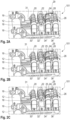
- Fig. 2A shows a view of a fiber sliver layer in an embodiment of a drafting device 101 after stopping the illustrated lower rollers 20, 22, 24, 26 of roller pairs, which are each composed of one of the lower rollers 20, 22, 24, 26 and a respective associated upper roller, in order to transport the intermediate fiber sliver 31 in a closed state during rotation of the roller pairs driven by the illustrated lower rollers 20, 22, 24, 26.
- an input lower roller 20 of an input roller pair, a middle lower roller 22 of a middle roller pair, an apron lower roller 24 of an apron roller pair and an output lower roller 26 of an output roller pair are shown in a row, which are part of the drafting device 101.
- the drafting device 101 is attached to a carrier 12 via a locking device 16.
- the input bottom roller 20 is driven in particular by an input bottom roller drive 30.
- the middle bottom roller 22 is driven in particular by a middle bottom roller drive 32.
- the apron bottom roller 24 is driven in particular by a belt bottom roller drive 34.
- the output bottom roller 26 is driven in particular by an output bottom roller drive 36.
- an apron 28 runs around the apron bottom roller 26, which can also be guided around an apron bridge 29 in order to build up tension in the aprons 28.
- the bottom rollers 20, 22, 24, 26 can be adjusted in their relative position to one another via an adjustment device 18.
- the lower part of the drafting device 101 shown here can be adjusted via a (not shown) top roller carrier, which carries the top rollers (not shown) of the respective roller pairs, wherein the top rollers form passive rollers due to the lack of their own drive.
- Fig. 2B shows a view of a start of the warm-up of the apron bottom roller 24 and/or the output bottom roller 26 in an embodiment of the drafting device 101, wherein the fiber band 31 is separated in a separation region 25.
- Fig. 2C shows a view of a fiber band layer after the end of the warm-up of the apron bottom roller 24 and/or output bottom roller 26 in an embodiment of the drafting device 101.
- the separation region 25 can be located in a region of a compressor which is located upstream of the apron bottom roller 24.
- the spinning station with the cleaning nozzle can go into the cleaning position. This allows superfluous fibers that are created during warm-up to be removed more easily without causing fiber blockages, particularly in a spinneret 40.
- the cleaning position is particularly variable and can have two different variants, as shown in the Figs. 3A and 3B shown and described below.
- Fig. 3A shows a view of a first cleaning position in an embodiment of the drafting device 101.
- a fiber band 31 is guided between an output upper roller 27 and an output lower roller 26 and transported by the rotation of the rollers.
- a spinning pressure within the spinneret 40 can be switched off and the spinneret 40 formed from two housing parts can be closed, i.e. not open.
- the fibers of the fiber band 31 or its fragments 14 can reach either the upper suction 13 or the lower suction 15, which are arranged in the area of the output roller pair formed by the output lower roller 26 and output upper roller 27 and are assigned to them, and can thus be sucked away.
- Fig. 3B shows a view of a second cleaning position in an embodiment of the drafting device 101.
- the spinning pressure can be switched on and the spinneret 40 can be cleaned by a relative movement in the direction of the double arrows of one of the two housing parts, which carries the spinning cone 42 of the spinneret 40, relative to the other housing part, which the fiber inlet 21 is opened and can be opened.
- the fibers of the fiber band 31 or its fragments 14 are sucked in particular through the fiber inlet 21 and via a fiber suction 23 communicating with the spinning chamber in the open position of the spinneret 40, i.e. in a spaced position of the spinning cone 42 to the fiber inlet 21 (not shown).
- step 7 of stopping the output bottom roller drive 36 and the apron bottom roller drive 34 the spinning station returns in particular to its normal spinning position (spinning pressure on, spinneret 40 closed as in Figure 3A shown).
- the next process steps then take place as described elsewhere.
- the second return 8 of the thread and the drafting device 101 or its lower rollers 20, 22, 24, 26 is/are accelerated using the parameters described elsewhere in step 9.
- the parameters in step 9 are particularly adapted so that they can be used to transport the fibers to the spinneret 40.
- significantly longer times are entered in particular.
- Fig. 4 The piecing ramp for this case is shown schematically (not to scale).
- Fig. 4 shows a schematic representation of a piecing ramp 420 of a driven output lower roller 26 compared to a piecing ramp 410 of a driven roller of a thread take-off.
- the time 415 is plotted on the X-axis in milliseconds (ms).
- the speed of the output lower roller 26 or the driven roller of the thread take-off is plotted on the Y-axis, approximately in units of revolutions per minute.
- a fiber band feed 400 is implemented in particular.
- the output lower roller 26 is already controlled in particular, which is why a piecing ramp 420 is already formed at this time.
- the thread take-off is still shut down at a zero point in time (selected as the starting point of the speed increase of the driven output lower roller 26 in a piecing ramp 420).
- a zero point in time selected as the starting point of the speed increase of the driven output lower roller 26 in a piecing ramp 420.
- the first start-up of the apron bottom roller drive 34 and the output bottom roller drive 36 without fiber sliver 31 takes place in this first time range. This prevents in particular the breakaway torque from having an effect in this zone.
- the piecing takes place when the drafting device 101 has already started up, which can reduce stress in the fiber sliver 31.
- Fig. 5 shows a schematic representation of a piecing ramp 530 with a support point 550.
- the speeds 505 are plotted against time 515. This results in piecing ramps 510 for a thread take-off roller drive or for the driven thread take-off roller, a piecing ramp 520 for an output bottom roller drive 36 or for the driven output bottom roller 26 and a piecing ramp 530 with a support point for an apron bottom roller drive 34 or for the driven apron bottom roller 24.
- a first speed stage 551 is formed in front of a first support point 550.
- the thread take-off can remain in a dwell time 540.
- the dwell time 540 of the thread take-off runs in particular in such a way that the thread end is held in the spinning chamber and enables the preparation of the drafting device 101 to be set. This is in step 10 in the Fig. 1 shown and described in this regard.
- the thread take-off runs up in particular when its dwell time 540 has elapsed in accordance with the entered acceleration, during which the drafting device 101 also runs up in particular.
- the thread is thereby drawn out of the spinning chamber in particular and the piecing process is ended in particular after the run-up times have elapsed.
- the total run-up time 560 of the drafting device 101 is indicated, as is the total run-up time 570 of the thread take-off.
- Fig. 6 shows a schematic representation of a piecing ramp 630 for an output bottom roller drive or for the driven output bottom roller 26 with S-grinding 610, 620 as an example of a process parameter.
- the speed 605 is plotted over time 615.
- the acceleration of the drives (of the bottom rollers 20, 22, 24, 26) is not exclusively linear, but with an S-curve that can be adjustable. This allows extreme accelerations to be avoided.
- the S-grinding 610, 620 can be implemented both for the thread take-off and for the drafting device 101 or its driven bottom rollers 20, 22, 24, 26.
- Fig. 7 shows acceleration ramps (speed 705 over time 715) of the drafting device 101, whereby only one support point 725 can be formed during acceleration, in the case of an acceleration ramp 710 of a thread take-off roller drive.
- An acceleration ramp 720 of an output lower roller 26 is shown, as is the acceleration ramp 730 of an input lower roller 20.
- Fig. 8 shows acceleration ramps (speed 705 over time 715) of the drafting device 101, whereby three support points 725, 735, 745 can be formed during acceleration at an acceleration ramp 720 of an output bottom roller 26.
- the three support points 725, 735, 745 mean in particular a setting of a variable speed 705, which can be reached after a variable time 715. This change can prevent, for example, the piecing device from leaning towards a thin point after the binding zone. This results in a more flexible design of the fiber mass during piecing.
- isolated features can also be selected from the combinations of features disclosed here and used in combination with other features to define the subject matter of the claim, dissolving any structural and/or functional connection that may exist between the features.
Landscapes
- Engineering & Computer Science (AREA)
- Mechanical Engineering (AREA)
- Textile Engineering (AREA)
- Spinning Or Twisting Of Yarns (AREA)
Applications Claiming Priority (1)
| Application Number | Priority Date | Filing Date | Title |
|---|---|---|---|
| LU504421A LU504421B1 (de) | 2023-06-06 | 2023-06-06 | Streckwerkvorrichtung, Spinnstelle und Verfahren |
Publications (1)
| Publication Number | Publication Date |
|---|---|
| EP4474538A1 true EP4474538A1 (fr) | 2024-12-11 |
Family
ID=86851629
Family Applications (1)
| Application Number | Title | Priority Date | Filing Date |
|---|---|---|---|
| EP24180095.2A Pending EP4474538A1 (fr) | 2023-06-06 | 2024-06-05 | Dispositif d'étirage, poste de filage et procédé |
Country Status (6)
| Country | Link |
|---|---|
| US (1) | US20240410089A1 (fr) |
| EP (1) | EP4474538A1 (fr) |
| JP (1) | JP2024175678A (fr) |
| CN (1) | CN119082952A (fr) |
| LU (1) | LU504421B1 (fr) |
| MX (1) | MX2024006779A (fr) |
Citations (2)
| Publication number | Priority date | Publication date | Assignee | Title |
|---|---|---|---|---|
| US5809764A (en) * | 1996-01-30 | 1998-09-22 | Murata Kikai Kabushiki Kaisha | Piecing method for a spinning machine |
| EP1072702A2 (fr) * | 1999-07-28 | 2001-01-31 | Murata Kikai Kabushiki Kaisha | Dispositif de filage et procédé à filer |
Family Cites Families (5)
| Publication number | Priority date | Publication date | Assignee | Title |
|---|---|---|---|---|
| DE4030100C2 (de) * | 1990-09-22 | 2000-03-23 | Schlafhorst & Co W | Verfahren und Einrichtung zum Bestimmen der Änderungen von Kriterien eines automatischen Anspinnvorgangs |
| JP2616428B2 (ja) * | 1994-01-25 | 1997-06-04 | 村田機械株式会社 | 紡績機の糸継ぎ方法 |
| JP2658901B2 (ja) * | 1994-09-05 | 1997-09-30 | 村田機械株式会社 | 紡績装置 |
| DE50111354D1 (de) * | 2000-12-22 | 2006-12-14 | Rieter Ag Maschf | Verfahren zum Ansetzen eines in einer Spinnstelle gebildeten Garnes oder zum Anspinnen, sowie zur Durchführung des Verfahrens ausgerüstete Spinnstelle |
| CH709953A1 (de) * | 2014-07-30 | 2016-02-15 | Rieter Ag Maschf | Verfahren zum Betrieb einer Luftspinnmaschine. |
-
2023
- 2023-06-06 LU LU504421A patent/LU504421B1/de active IP Right Grant
-
2024
- 2024-05-31 MX MX2024006779A patent/MX2024006779A/es unknown
- 2024-06-05 EP EP24180095.2A patent/EP4474538A1/fr active Pending
- 2024-06-05 CN CN202410724707.0A patent/CN119082952A/zh active Pending
- 2024-06-05 JP JP2024091055A patent/JP2024175678A/ja active Pending
- 2024-06-05 US US18/734,432 patent/US20240410089A1/en active Pending
Patent Citations (2)
| Publication number | Priority date | Publication date | Assignee | Title |
|---|---|---|---|---|
| US5809764A (en) * | 1996-01-30 | 1998-09-22 | Murata Kikai Kabushiki Kaisha | Piecing method for a spinning machine |
| EP1072702A2 (fr) * | 1999-07-28 | 2001-01-31 | Murata Kikai Kabushiki Kaisha | Dispositif de filage et procédé à filer |
Also Published As
| Publication number | Publication date |
|---|---|
| LU504421B1 (de) | 2024-12-06 |
| MX2024006779A (es) | 2025-01-09 |
| US20240410089A1 (en) | 2024-12-12 |
| JP2024175678A (ja) | 2024-12-18 |
| CN119082952A (zh) | 2024-12-06 |
Similar Documents
| Publication | Publication Date | Title |
|---|---|---|
| DE3744757A1 (de) | Verfahren und vorrichtung zum anspinnen einer mit einem pneumatischen drallorgan arbeitenden spinnvorrichtung | |
| EP3148913A1 (fr) | Procédé permettant de faire fonctionner une machine textile et machine textile servant à produire une mèche | |
| EP3140440B1 (fr) | Machine textile et procédé pour faire fonctionner une telle machine | |
| DE19815518A1 (de) | Verfahren und Vorrichtung zum Spinnen mit unterdrücktem Fadenballon | |
| DE3926227C2 (fr) | ||
| EP1774073B1 (fr) | Peigneuse | |
| EP0578955A1 (fr) | Procédé de préparation d'un enroulement de nappe | |
| EP3839114B1 (fr) | Procédé d'agencement d'une bande de fibre sur une unité de filage d'un métier à filer | |
| LU504421B1 (de) | Streckwerkvorrichtung, Spinnstelle und Verfahren | |
| EP4389947B1 (fr) | Poste de filage d'un métier à filer à jet d'air et procédé de mise en uvre d'un processus de filage sur un tel poste de filage | |
| EP2980284B1 (fr) | Procede de fabrication d'un fil produit par jet d'air | |
| DE102007038871A1 (de) | Verfahren zum Anspinnen an Textilmaschinen mit einer Mehrzahl von Spinnstellen | |
| EP3919659B1 (fr) | Procédé de filage d'un métier à filer à rotor à bout libre et métier à filer à rotor à bout libre | |
| DE3401316A1 (de) | Verfahren zum stillsetzen und wiederanfahren eines oe-friktionsspinnaggregates | |
| DE19821643B4 (de) | Verfahren und Offenend-Rotorspinnmaschine zum Anspinnen eines Fadenendes | |
| DE102021101809A1 (de) | Kämmmaschine und Verfahren zum Betrieb einer Kämmmaschine | |
| WO2001055490A2 (fr) | Procede de filature a fibres liberees, au moyen d"un rotor | |
| CH690009A5 (de) | Verfahren zum Anspinnen des Garnes an Offen-End-Spinnmaschinen und Vorrichtung zur Ausführung des Verfahrens. | |
| EP4389948B1 (fr) | Préparation de ruban de fibres | |
| EP4416326B1 (fr) | Peigneuse et procédé de fonctionnement d'une peigneuse | |
| DE10146608A1 (de) | Luftspinnvorrichtung | |
| CH691973A5 (de) | Verfahren zum Offenend-Spinnen. | |
| EP0826804A1 (fr) | Méthode et dispositif pour rattacher un fil dans un métier à filer à bout ouvert | |
| DE3342472A1 (de) | Verfahren zum anspinnen eines garnes an einem spinnaggregat einer oe-friktionsspinnmaschine und oe-friktionsspinnmaschine | |
| EP1564317A1 (fr) | Méthode pour obtenir une partie de fil rattachée de masse constante dans un procédé de filage à vortex |
Legal Events
| Date | Code | Title | Description |
|---|---|---|---|
| PUAI | Public reference made under article 153(3) epc to a published international application that has entered the european phase |
Free format text: ORIGINAL CODE: 0009012 |
|
| STAA | Information on the status of an ep patent application or granted ep patent |
Free format text: STATUS: THE APPLICATION HAS BEEN PUBLISHED |
|
| AK | Designated contracting states |
Kind code of ref document: A1 Designated state(s): AL AT BE BG CH CY CZ DE DK EE ES FI FR GB GR HR HU IE IS IT LI LT LU LV MC ME MK MT NL NO PL PT RO RS SE SI SK SM TR |
|
| STAA | Information on the status of an ep patent application or granted ep patent |
Free format text: STATUS: REQUEST FOR EXAMINATION WAS MADE |
|
| 17P | Request for examination filed |
Effective date: 20250611 |
|
| GRAP | Despatch of communication of intention to grant a patent |
Free format text: ORIGINAL CODE: EPIDOSNIGR1 |
|
| STAA | Information on the status of an ep patent application or granted ep patent |
Free format text: STATUS: GRANT OF PATENT IS INTENDED |
|
| INTG | Intention to grant announced |
Effective date: 20251209 |
|
| GRAS | Grant fee paid |
Free format text: ORIGINAL CODE: EPIDOSNIGR3 |
|
| GRAA | (expected) grant |
Free format text: ORIGINAL CODE: 0009210 |
|
| STAA | Information on the status of an ep patent application or granted ep patent |
Free format text: STATUS: THE PATENT HAS BEEN GRANTED |