EP4474577A1 - Planierer - Google Patents
Planierer Download PDFInfo
- Publication number
- EP4474577A1 EP4474577A1 EP23178505.6A EP23178505A EP4474577A1 EP 4474577 A1 EP4474577 A1 EP 4474577A1 EP 23178505 A EP23178505 A EP 23178505A EP 4474577 A1 EP4474577 A1 EP 4474577A1
- Authority
- EP
- European Patent Office
- Prior art keywords
- tool
- grader
- chassis
- adjustment mechanism
- arm
- Prior art date
- Legal status (The legal status is an assumption and is not a legal conclusion. Google has not performed a legal analysis and makes no representation as to the accuracy of the status listed.)
- Withdrawn
Links
Images



Classifications
-
- E—FIXED CONSTRUCTIONS
- E01—CONSTRUCTION OF ROADS, RAILWAYS, OR BRIDGES
- E01C—CONSTRUCTION OF, OR SURFACES FOR, ROADS, SPORTS GROUNDS, OR THE LIKE; MACHINES OR AUXILIARY TOOLS FOR CONSTRUCTION OR REPAIR
- E01C19/00—Machines, tools or auxiliary devices for preparing or distributing paving materials, for working the placed materials, or for forming, consolidating, or finishing the paving
- E01C19/22—Machines, tools or auxiliary devices for preparing or distributing paving materials, for working the placed materials, or for forming, consolidating, or finishing the paving for consolidating or finishing laid-down unset materials
- E01C19/42—Machines for imparting a smooth finish to freshly-laid paving courses other than by rolling, tamping or vibrating
Definitions
- the invention relates to a machine for leveling a concrete surface.
- grader For the purpose of leveling a surface of unset (or unhardened) concrete, it is known to use a machine, called a “grader”, equipped with a tool dedicated to this purpose, called a “leveling tool”.
- the invention relates to graders for which the tool is mechanically coupled to a mechanical tool-carrying structure arranged in a cantilever manner at one end of a chassis of the grader, such that the chassis and the tool move together, following each other in this order along a movement path of the grader, at an essentially constant distance from each other as the surface is leveled.
- This type of grader is typically small in size and light in weight.
- the chassis is mounted on wheels, which are designed to move across unleveled concrete, pulling the implement while leveling the surface.
- Publications US 2003/068200 A1 And US 8,038,366 B2 hereinafter referred to as D1 and D2 respectively, disclose such graders.
- the leveling tool may be height adjusted by one or more jacks. These may be arranged along masts supported at the tool carrier structure (reference 318 of Figure 16 of D1 and reference 330 of Figure 17 of D2) and between the chassis and the tool carrier structure (reference 321 of Figure 16 of D1 and reference 230 of Figure 11 of D2). Jacks at these two separate locations are used in D1 such that the height of the leveling tool is primarily determined by the jack arranged between the chassis and the tool carrier structure, with the jack(s) arranged along masts at the tool carrier structure being used for minor height adjustments.
- Maintaining the orientation of the leveling tool by means of a tensioner or support bar is also known from the prior art (reference 325 of figure 16 of D1 and reference 234 of figure 11 of D2).
- a tensioner is mounted between the frame and the tool-carrying structure.
- one or more structure arms also extend between the frame and the tool-carrying structure for the purpose of supporting the leveling tool (reference 323 of Figure 16 of D1 and reference 232 of Figure 11 of D2).
- An object of the invention is to provide a grader for leveling a concrete surface which is sufficiently light for such applications.
- the grader according to the invention allows an advantageous mass distribution inducing a reduced weight compared to similar graders of the prior art.
- the orientation adjustment mechanisms and height adjustment mechanisms are not arranged between the chassis and the tool-carrying structure; they are mounted on either side of the front end of the arm, which makes it possible to offset one of the two, preferably the height adjustment mechanism, at the chassis, in front of the arm, and thus to reduce the weight behind the chassis, between the chassis and the tool-carrying structure. This consequently makes it possible to reduce the overall weight of the grader.
- this weight is at most 800 kg, and more preferably, it is approximately 750 kg for a machine whose tool has a useful width of at least 3 m.
- This weight reduction allows the grader to operate on meshes or insulations that have low crushing resistance.
- it can be used in the manufacture of a concrete surface intended for a refrigerated area or a hybrid concrete surface, comprising for example recycled fibers, or even a concrete surface on a mesh having a small thickness of concrete, for example about ten centimeters, surmounting the mesh.
- grade is interchangeable with the terms “levelling machine” or more generally with the terms “treating machine” in the case where the treatment includes levelling of unset concrete, this operation being known under the English name of "screed".
- concrete generally refers, in an unset (or unhardened) state, to a flexible paste of variable homogeneity, preferably comprising a mixture of sand and cement, intended to be cast in a dedicated space prior to its hardening. This occurs after a setting time.
- the dedicated space is, for example, a support, a mold or a cavity.
- Concrete is a very widely known construction material which makes it possible to form coatings and construction elements of great strength.
- the concrete is preferably cast so as to form a concreted surface.
- surface is not to be understood in this document as referring to a strictly two-dimensional (mathematical) object.
- a concrete surface necessarily has a certain thickness of concrete.
- the term "surface” is used in view of the fact that in general, the exterior surface of the concrete once set and leveled is that which is visible externally, typically when designing a concrete covering, floor or slab.
- the unset concrete poured into the space dedicated to the formation of the surface generally includes irregularities and variations in thickness forming a relief, hence the need to level this surface with a grader intended for this purpose. This concrete therefore does not extend only in a two-dimensional way. More generally, in the context of this document, the term “surface” is interchangeable with the term "extent”.
- the chassis of the grader comprises a rear chassis end and a front chassis end.
- the movement of the grader is generally carried out such that the front end precedes the rear end according to the trajectory followed when leveling the concrete surface.
- the terms "front” and “rear” preferably refer in this context to a positioning in this regard.
- an element is behind (resp. in front of) another if it precedes (resp. follows) the latter according to a vector directed from the rear chassis end to the front chassis end or, in other words, according to said trajectory.
- the leveling tool is preferably arranged behind the chassis such that it is pulled by the grader when leveling a concrete surface. It is preferably coupled to the chassis via the aforementioned rear chassis end.
- the terms “height adjustment” refer preferentially in this document to an adjustment of a distance separating the tool and the tool-carrying structure from the concrete surface, or alternatively, of a plane on which the wheels rest (“wheel support plane”), or alternatively, of a plane along which the chassis extends.
- the term “height” has in particular the entirely usual meaning that a person skilled in the art would give it in the technical context of the invention.
- the height adjustment mechanism allows the relative height of the tool and the tool holder to be changed relative to the chassis depending on the type of leveling desired, for example, depending on the thickness of the underlying concrete.
- the height adjustment mechanism preferably allows a variation amplitude to be obtained in height of at least 25 cm, preferably about 40 cm. This height varies for example from about 5 cm (to within 2.5 cm) above the wheel support plane for small concrete thicknesses, to about 40 cm (to within 2.5 cm) above the wheel support plane for large concrete thicknesses.
- orientation adjustment preferably refer in this document to an adjustment of an angle of attack of the concrete surface by the tool.
- this angle is for example that between a plane according to which a contact surface of the rule with the concrete surface ("operating surface of the rule") and the support plane of the wheels or, alternatively, the angle between the operating surface of the rule and a plane according to which the chassis extends.
- the term "orientation” has in particular the entirely usual meaning that a person skilled in the art would give it in the technical context of the invention.
- the orientation adjustment mechanism preferably makes it possible to obtain an amplitude of variation of said angle of at least 30°, and preferably of approximately 45°.
- the orientation adjustment mechanism makes it possible to modify this angle according to the type of leveling desired. It is generally used in combination with the height adjustment mechanism. Indeed, as the two mechanisms are mounted (in series) on either side of the front end of the arm, a modification of the aforementioned height in most embodiments of the invention is likely to affect the orientation of the arm, of the orientation adjustment mechanism and therefore of the tool and of the tool-holder structure.
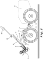
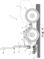
- the orientation adjustment mechanism then makes it possible to re-establish the orientation of the tool and of the tool-holder structure so that the aforementioned angle remains constant as shown in figures 3 And 4 hereinafter introduced.
- the orientation adjustment mechanism can also be used for other purposes such as to orient the tool transversely towards an operator as much as possible for the purpose of cleaning the tool. This application is particularly illustrated in figure 2 hereinafter introduced.
- the height (or orientation) adjustment mechanism comprises, and preferably essentially corresponds to, a cylinder, preferably hydraulic, and preferably arranged linearly, without the invention being limited thereto.
- a cylinder preferably hydraulic, and preferably arranged linearly
- Other types of actuators may be used within the scope of the invention.
- such a cylinder has the advantage of being simple to implement, while being able to develop a significant force, and to allow movement of the tool and the tool-holder structure in height (resp. in orientation) within a determined interval.
- the height-holding arm (called “the arm”) preferably corresponds to a rigid mechanical structure intended to support and/or maintain the mechanical coupling between, on the one hand, the tool-carrying structure (and the tool coupled thereto) and, on the other hand, the chassis.
- the arm makes it possible in particular to support and/or maintain the height and orientation adjustment mechanisms mounted on its front end.
- the arm may have various shapes. It extends from the tool-carrying structure on which it is mounted, up to the chassis level. It thus extends "from the back to the front" of the grader according to the previous introduction of these two terms, so that it has a rear end mounted on the tool-carrying structure and a front end opposite the rear end, in particular in the front-rear direction.
- the arm also preferably extends in height, so that it has a partly oblique shape.
- the front end overhangs the rear end. This advantageously makes it possible to mount the orientation and height adjustment mechanisms on the front end of the arm overhanging the tool and the tool-carrying structure, and therefore to control the movements of these from above.
- the arm has a substantially pyramidal shape.
- This shape has the advantage of giving it good rigidity while providing space in this shape for arranging various hydraulic and electrical components.
- This shape can be more precisely described as follows.
- the arm may have two oblique extension flaps mirrored one another along two trapezoidal or triangular surfaces which meet at the front end.
- the surfaces make it possible to increase the rigidity of the arm. They are hollowed out with an internal orifice to limit the weight of the arm according to an optional embodiment.
- the surfaces are preferably each extended by a retaining bar whose end rear is mounted on the tool-carrying structure. Each bar is a "lower" extension of a surface in the sense that the surface surmounts the bar. The bar at this location reinforces the rigidity of the arm, by helping to lighten the part of the arm facing rearward, i.e. towards the tool-carrying structure.
- the rear end of the arm then comprises two separate parts formed by the rear end of each bar.
- the arm and more precisely its rear end, is preferably mounted on the tool-carrying structure by means of a pivot connection.
- This pivot connection is double and arranged at the rear end of the bars in the aforementioned embodiment. It makes it possible to implement a relative rotation of the tool-carrying structure with respect to the arm, i.e. its pitching.
- the arm is also (and obviously) mechanically coupled to the chassis in the grader according to the invention.
- This coupling is preferably achieved by means of a pivot connection, so that the arm is mounted on the chassis via this pivot connection.
- the part of the arm thus connected to the chassis is typically in front of the arm, without however corresponding to the front end.
- the connection is preferably provided at the front end of each bar, the latter then being surmounted or overhung by the front (overall) end of the arm.
- the pivot connection is therefore double in this case.
- the pivot connection between the arm and the chassis more generally makes it possible to implement a relative rotation of the arm relative to the chassis when the height adjustment mechanism is actuated.
- the terms "on either side” are used to physically locate elements, including height and orientation adjustment mechanisms, on either side of another element, these sides preferably being opposite.
- the orientation adjustment mechanism is mounted on a rear side of the front end of the arm, while the height adjustment mechanism is mounted on a front side, opposite said rear side, of the front end of the arm.
- the orientation adjustment mechanism is mounted on the one hand on the front end of the arm, and on the other hand on the tool-carrying structure.
- the height adjustment mechanism is mounted on the one hand on the frame, and on the other hand on the front end of the arm.
- these embodiments induce a series of successive couplings from the tool-carrying structure to the chassis via the orientation adjustment mechanism, the front end of the arm, and the height adjustment mechanism.
- These couplings make it possible to move the tool (and the tool-carrying structure) in height and to orient it adequately while offsetting part of the mechanisms at the chassis level, i.e. further forward, compared with a configuration in which the arms and the orientation and height adjustment mechanisms would all be at the same level, between the tool-carrying structure and the chassis, which induces a much better distribution of weight at the level of each wheel of the grader, and between the front and rear axles or half-axles supporting the wheels, hence a gain in overall weight of the grader.
- the two aforementioned forms have a common side which is defined by the arm and they can be considered in a coplanar manner.
- This advantageous mechanical arrangement induces good rigidity of the coupling between the tool-carrying structure and the chassis while remaining simple to implement according to the technical objectives described in terms of the weight of the grader.
- the actuation of the orientation adjustment mechanism affects the geometry of the aforementioned first shape, while the actuation of the height adjustment mechanism affects the geometry of the aforementioned second shape and the positioning of the aforementioned first shape, by tilting the latter without deforming or modifying it.
- the pivot connections of the arm with the tool-holder structure and the chassis allow these movements to be carried out.
- a chassis comprising two parts mechanically coupled by an articulation.
- Such a chassis is more lightweight without losing maneuverability because the front part of the chassis guides the rear part via the articulation and/or a directional cylinder. It is also not necessary to provide a large space between the chassis and the wheels in order to arrange steering means, which also contributes to lightening the grader.
- Such an articulated chassis also makes it possible to maintain regular mechanical contact between the wheels and the ground on which they move even if the ground has reliefs or irregularities. Such a chassis is therefore advantageous in this respect for moving the grader on a trellis for example.
- the height adjustment mechanism is preferably mounted at the articulation.
- the mounting of this mechanism on the grader chassis is done at the front end of the rear part of the chassis, or as far as possible from the tool-carrying structure, which again contributes to a better mass distribution of the grader.
- the grader comprises a mechanism for adjusting the height of the tool relative to the tool-carrying structure.
- This preferably involves one or two lifting cylinders carrying the tool which are arranged on either side of the tool-carrying structure.
- this arrangement can be achieved by supporting the cylinders by means of one or two lifting masts.
- the cylinder(s) are typically hydraulic cylinders. Other cylinders, such as electric actuators, would however not depart from the scope of the invention.
- the height adjustment mechanism is configured to adjust the relative height of the tool relative to the tool-carrying structure, for example according to the quality and flowability of the concrete, the desired leveling tolerance and/or additional parameters.
- the height adjustment is preferably made possible with an adjustment amplitude of the same order as an adjustment amplitude obtained by the height adjustment mechanism.
- the adjustment amplitude may be between 75 and 125% of the adjustment amplitude or vice versa.
- Respective values for these amplitudes are for example 30 and 40 cm, or 35 and 35 cm.
- the determination of the height of the tool is therefore distributed between the actions of the height adjustment mechanism and those of the mechanism height adjustment, which distributes the weights associated with these mechanisms while limiting the height of the masts and jacks arranged on the tool-carrying structure if applicable. It is therefore easier to use the grader in underground car parks with a generally limited height because the height is not determined only at the level of the tool-carrying structure, which would require a greater height of mast and jacks.
- adjustment and height adjustment amplitudes of the same order make it possible to limit the manipulations of the height and orientation adjustment mechanisms during each leveling operation.
- the adjustment amplitude is large enough to allow the height of the tool to be adequately adjusted between successive concrete surfaces to be leveled under defined technical conditions (location, type of concrete, etc.).
- the height of the tool and the tool-holder structure is adjusted globally according to the operations to be carried out, possibly adjusting the height of the tool via the adjustment mechanism between successive concrete surfaces (for example, if the fluidity of the concrete varies throughout the day).
- a height adjustment mechanism comprising two cylinders arranged on either side at the level of the tool-carrying structure makes it possible to tilt the tool by an angle of up to 10° relative to the tool-carrying structure. To do this, it is sufficient to adjust the height of one side of the tool positively by means of one cylinder, and the height of the other side of the tool negatively by means of the other cylinder. Thus, it is made possible to easily carry out leveling on a slope relative to the path of the grader.
- the determination of the height (or elevation) of the tool generally relies on a laser system as is known to a person skilled in the art. More precisely, a reference plane is generated in the operating area of the grader by means of a source of one or more laser beams. This reference plane can then be captured by receivers mounted on the tool-carrying structure, for example, on the elevation masts when it comprises them. It is thus possible to ensure that the tool (but not necessarily the tool-carrying structure) remains at a desired height relative to this reference plane, and therefore that the leveling is made according to the desired flat surface. In the event of deviation from this, the height adjustment mechanism allows the height of the tool to be adjusted, without it being necessary to intervene on the height adjustment mechanism. Leveling by means of a laser-generated reference plane is generally referred to as "laser screed". This is a preferred embodiment of the invention, so that the leveler is preferably provided with the aforementioned laser receivers mounted on the tool-carrying structure.
- the elevation cylinders are preferably each equipped with a position sensor.
- the height of the tool can be modeled on its last known position value(s) thanks to the position sensor(s) via the corresponding elevation cylinder(s).
- the mechanical coupling of the rule to the tillage implement is typically such that it allows the rule to move in a floating manner on the concrete surface while being subjected to few constraints.
- the tool is generally equipped with an inclinometer in order to monitor the orientation of the tool, and therefore the slope of the concrete surface leveled by it.
- This inclinometer is preferably placed at a distance from the rule, on the tillage implement, because it can be disturbed by the vibrations of the rule.
- the mechanical coupling of the rule with the tillage implement so as to constrain minimally is conducive to the at least partial transmission of the vibrations of the rule, so that the inclinometer and therefore the leveling result is likely to be affected. Beyond these considerations, it is also preferable not to subject the instrument, and therefore too many mechanical elements of the grader, to vibrations which are likely to affect their operation or even their service life.
- the grader tool is such that the rule is mechanically coupled in a cantilever manner to the tillage implement by an elastic suspension by which a first (mechanical) axis integral with the rule engages in a support comprising an elastomeric material, for example rubber.
- This engagement is such that the part of this axis engaged in the support is surrounded at least partially by the elastomeric material, which advantageously dampens the vibrations of the rule, and reduces their transmission to the tillage instrument, therefore to the possible inclinometer.
- Elastomeric materials are known to those skilled in the art and have a high elastic resistance to compression and extension. They have the advantage of withstanding deformations without breaking while being able to easily return to their initial shape. This mechanical coupling is therefore resistant, while allowing the rule to float partially behind the tillage instrument, transmitting less vibration to it.
- a second axis integral with the tillage implement engages in the support.
- This engagement is preferably also such that the part of this second axis engaged in the support is at least partially surrounded by the elastomeric material, which provides advantages symmetrical to those described above at the level of the agricultural implement.
- the engagement of the second axis in the support allows a degree of variation in height within the elastomeric material and the engagement of the first axis in the support allows a degree of variation in orientation in the elastomeric material.
- the first and second axes engage in separate orifices of the support provided for this purpose, the support making it possible to rigidly maintain the two orifices at a distance from each other.
- Each of the orifices is bordered by the elastomeric material.
- a POSTA ® elastic guide arm of the AS-PV type is an example of such a support.
- the first axis is mechanically fixed to a stop mounted on the tillage implement.
- This stop aims to constrain the possible movement of the rule and therefore, advantageously, to further limit the vibrations that it can transmit to the tillage implement, while maintaining a movement of the rule on the partially floating concrete surface.
- the grader is distinguished from the machines cited in the prior art in that it is preferably fully electric. More specifically, the grader preferably comprises an electrical power supply, for example one or more batteries, coupled to at least one electric motor and a hydraulic system for powering functionalities of the grader, these features including any movement of the wheels and the tool. Preferably, all the features of the machine are thus powered.
- an electrical power supply for example one or more batteries, coupled to at least one electric motor and a hydraulic system for powering functionalities of the grader, these features including any movement of the wheels and the tool.
- all the features of the machine are thus powered.
- the hydraulic system preferably comprises hydraulic motors and/or actuators as known to those skilled in the art.
- This hydraulic system makes it possible, for example, to induce a modification of the height and orientation of the tool and the tool-holder structure by the height and orientation adjustment mechanisms as detailed above.
- the invention finally provides a method of manufacturing a concrete surface comprising using a grader according to the invention to level the concrete surface.
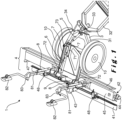
- the grader 1 comprises a basic chassis 3 mounted on a pair of wheels 12 called “front” and a pair of wheels 10 called “rear”.
- the front wheels 12 (resp. rear wheels 10) are arranged at the chassis 3 by aligned half-axles as can be seen from the figure 6 for example.
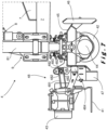
- Chassis 3 comes in two parts: a part called “front” 32, and a part called “rear” 31, visible in figures 1 And 6 . These parts 31, 32 are articulated together by a joint 33 which is itself coupled to one or more steering cylinders 34.
- a chassis 3 has the advantage of being light and steerable without providing space between the chassis 3 and the wheels 10, 12 to arrange a steering mechanism there.
- the joint 33 allows the wheels 10, 12 to be more easily in contact with a ground on which the grader 1 operates, even if this ground has a relief.
- the grader 1 is provided with a leveling tool 4 arranged behind the rear chassis part 31.
- the grader 1 preferably moves forward, that is to say so that its rear chassis part 31 follows its front chassis part 32 along its trajectory.
- the tool 4 is then pulled by the rest of the grader 1.
- the grader moves according to the vector V illustrated in figure 6 oriented from rear to front, as discussed in the disclosure of the invention.
- the terms "front” and “rear” are used to define a positional relationship of two elements with respect to the vector V. A grader 1 that would move in the opposite direction, however, does not depart from the scope of the invention.
- the aforementioned tool 4 is mechanically coupled in a cantilever manner to the chassis 3 by means of a tool-carrying structure 9 supporting the tool 4.
- This support is for example produced by two lifting masts 81 of the tool 4 arranged symmetrically on either side of the tool-carrying structure 9 and on which are mounted lifting cylinders constituting a height adjustment mechanism 8 of the tool relative to the tool-carrying structure 9.
- the tool 4 is thus supported at its ends.
- each elevation cylinder is surmounted by a laser receiver 82 for detecting a laser reference plane generated in the operating environment of the grader 1.
- the elevation cylinders are controlled on the basis of signals emitted by these receivers 82, so as to adjust the height of the tool 4 relative to the reference plane and to ensure that the leveling is done according to the desired slope and/or plane.
- These receivers 82 are typically coupled by a junction element 83 to the ends of the elevation masts 81 or directly to the ends of the tool 4.
- the tool-carrying structure 9 is in the form of a beam comprising attachments oriented upwards or downwards, perpendicular to a main direction of extension of the beam.
- the mechanical coupling of the tool 4 to the chassis 3 via the tool-carrying structure 9 is carried out via an arm 7 for maintaining the height of the tool-carrying structure 9 and the tool 4 relative to the chassis.
- This arm 7 has a substantially pyramidal shape having two trapezoidal flaps in mirror symmetry extending from the rear to the front, and in height.
- the arm 7 has two lower extensions in the form of mechanical bars extending the aforementioned flaps.
- Each bar comprises a rear end linked by a pivot connection 72 to a downwardly oriented attachment of the tool-carrying structure 9, and a front end linked by a pivot connection 73 to the chassis. It follows that the arm 7 can undergo a rotation relative to the chassis 3 and the tool-carrying structure 9 can undergo a rotation relative to the arm 7.
- the arm 7 has a rear end consisting of the rear ends of the aforementioned bars (at the positions of the pivot connections 72) and a front end at the junction of the two aforementioned flaps and around which a mounting part 71 is arranged.
- the rear end of the arm 7 is formed by the segments of the arm 7 furthest to the rear and the front end of the arm 7 is formed by the segment of the arm 7 furthest to the front. This second overhangs this first, and overcomes the direction of alignment of the two half-axles of the rear wheels 10, the latter being at the same level according to the vector V as the front end of the arm 7.
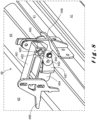
- the tool 4 and the tool-carrying structure 9 can be adjusted in orientation and in height relative to the frame 3 by means of an orientation adjustment mechanism 6 and a height adjustment mechanism 5, which consist of hydraulic cylinders.
- These adjustment mechanisms 5, 6 are mounted on either side of the front end of the arm 7. They are each fixedly held on one side on the front end of the arm 7 by the mounting part 71.
- the other side of the height adjustment mechanism 5 is mounted on the frame 3, for example at the joint 33, and the other side of the orientation adjustment mechanism 6 is mounted on a fastener facing upwards of the tool-carrying structure 9, at center thereof.
- the two hydraulic cylinders constituting these adjustment mechanisms 5, 6 extend in particular parallel to the vector V.
- the tool 4 is therefore mechanically coupled to the chassis 3 via the bars of the arm 7 on the one hand, and the orientation adjustment mechanism, the front end of the arm 7 and the height adjustment mechanism 5 on the other hand.
- the height adjustment mechanism 5 and the orientation adjustment mechanism 6 are arranged on either side of the direction of alignment of the half-axles of the rear wheels 10.
- This configuration makes it possible in particular to use a height adjustment mechanism 5 at the chassis 3, further forward, without unbalancing the grader 1 given the weight of the tool 4.
- the weight of the grader 1 at each wheel 10, 12 is thus better distributed, and lower because the elements of the mechanical coupling of the tool 4 with the chassis 3 having a weight carried at the rear require less compensation at the front.
- This compensation is carried out in a known manner by arranging heavier mechanical elements 11 such as a motor in front of the grader 1.
- the height adjustment mechanisms 5 and orientation 6 preferably operate synergistically when leveling a concrete surface so as to keep the elevation masts 81 in a vertical position and to validly exploit the signals from the receivers 82.
- the cylinder of the height adjustment mechanism 5 is retracted, and the cylinder of the orientation adjustment mechanism 6 is extended to keep the lifting masts 81 vertical, and therefore maintain an appropriate angle of attack of the concrete 2 with the tool 4.
- the cylinder of the height adjustment mechanism 5 is extended to bring the tool 4 sufficiently low, while the cylinder of the orientation adjustment mechanism 6 is retracted to keep the elevation masts 81 vertical, and thus maintain an appropriate angle of attack of the concrete with the tool 4.
- the adjustment mechanisms 5, 6 can however also operate in such a way as not to maintain a vertical position of the lifting masts 81. This is the case for example in figure 2 where the jacks constituting these adjustment mechanisms 5, 6 are retracted to the maximum, which makes it easier to clean the tool 4 by raising it on the one hand, and tilting it on the other hand. It is thus very easy for an operator facing the tool 4 to clean the lower base of the latter which is generally in contact with the concrete 2.
- the tool 4 comprises from front to back a scraper 46 for predefining a slope of the concrete surface 2; a tillage implement 42, 45 surmounted by the tool-carrying structure 9 and arranged to more finely define the concrete surface 2; and a rule 41 for leveling the concrete surface 2 and mechanically coupled in a cantilever manner to the tillage implement 42, 45 by an elastic suspension 48.
- a motor 43 is mounted on the rule 41 to induce vibrations thereof, so as to compact and smooth the concrete 2.
- the rule 41 finalizes the concrete surface 2.
- the tillage implement 42, 45 comprises a screw (endless) 42 induced in rotation about an axis orthogonal to the vector V by a rotary motor 44.
- the screw 42 is surrounded laterally and surmounted by a protective box 45 on which the lifting masts 81 are mounted.
- This box 45 has a projecting end 47 making it possible to deport outside the concrete surface 2 the surplus concrete 2 carried by the screw 42.
- the aforementioned elastic suspension 48 defining the mechanical coupling of the rule 41 to the ploughing instrument 42, 45 is detailed in figures 7 And 8 according to two views on either side of the elastic suspension 48.
- This comprises a support 481 in the form of a rectangular structure comprising two end orifices within which are arranged elements of elastomer material 482, for example, to border the orifices.
- the movements of the vibrating rule 41 are thus damped by the elastomer material 482.
- a stop 484 can further be mounted on the box 45 and fixed to the first axis 485 via another fixing part 487, capable to constitute an extension of the aforementioned fixing part 488. The stop 484 thus implemented further limits the movements of the rules 41.
- the aforementioned elastic suspension 48 is particularly advantageous when an inclinometer is mounted on the box 45 to minimize the transmission of vibration or other movements of the rule 41 to the inclinometer.
- the invention relates to a grader 1 for leveling a concrete surface 2.
- the grader 1 is provided with a leveling tool 4 adjustable both in height and in orientation by means of mechanisms 5, 6 arranged in such a way as to make it possible to lighten the grader 1.
Landscapes
- Engineering & Computer Science (AREA)
- Architecture (AREA)
- Civil Engineering (AREA)
- Structural Engineering (AREA)
- On-Site Construction Work That Accompanies The Preparation And Application Of Concrete (AREA)
Priority Applications (1)
| Application Number | Priority Date | Filing Date | Title |
|---|---|---|---|
| EP23178505.6A EP4474577A1 (de) | 2023-06-09 | 2023-06-09 | Planierer |
Applications Claiming Priority (1)
| Application Number | Priority Date | Filing Date | Title |
|---|---|---|---|
| EP23178505.6A EP4474577A1 (de) | 2023-06-09 | 2023-06-09 | Planierer |
Publications (1)
| Publication Number | Publication Date |
|---|---|
| EP4474577A1 true EP4474577A1 (de) | 2024-12-11 |
Family
ID=86760208
Family Applications (1)
| Application Number | Title | Priority Date | Filing Date |
|---|---|---|---|
| EP23178505.6A Withdrawn EP4474577A1 (de) | 2023-06-09 | 2023-06-09 | Planierer |
Country Status (1)
| Country | Link |
|---|---|
| EP (1) | EP4474577A1 (de) |
Citations (6)
| Publication number | Priority date | Publication date | Assignee | Title |
|---|---|---|---|---|
| US20030068200A1 (en) | 2001-10-09 | 2003-04-10 | Quenzi Philip J. | Light weight apparatus for screeding and vibrating uncured concrete surfaces |
| KR100995727B1 (ko) * | 2010-05-18 | 2010-11-19 | 손강국 | 콘크리트 바닥 시공용 평탄 작업장치 |
| US8038366B2 (en) | 2004-07-26 | 2011-10-18 | Somero Enterprises, Inc. | Wheeled concrete screeding device |
| FR2996865A1 (fr) * | 2012-10-17 | 2014-04-18 | Yves Blandin | Dispositif de compensations electriques et electroniques pour nivellements et compactages |
| EP2891750A1 (de) * | 2014-01-07 | 2015-07-08 | Stehr Baumaschinen GmbH | An einem trägergerät verstellbar angeordneter plattenverdichter |
| CN115233521A (zh) * | 2021-04-23 | 2022-10-25 | 广东博智林机器人有限公司 | 整平机器人 |
-
2023
- 2023-06-09 EP EP23178505.6A patent/EP4474577A1/de not_active Withdrawn
Patent Citations (6)
| Publication number | Priority date | Publication date | Assignee | Title |
|---|---|---|---|---|
| US20030068200A1 (en) | 2001-10-09 | 2003-04-10 | Quenzi Philip J. | Light weight apparatus for screeding and vibrating uncured concrete surfaces |
| US8038366B2 (en) | 2004-07-26 | 2011-10-18 | Somero Enterprises, Inc. | Wheeled concrete screeding device |
| KR100995727B1 (ko) * | 2010-05-18 | 2010-11-19 | 손강국 | 콘크리트 바닥 시공용 평탄 작업장치 |
| FR2996865A1 (fr) * | 2012-10-17 | 2014-04-18 | Yves Blandin | Dispositif de compensations electriques et electroniques pour nivellements et compactages |
| EP2891750A1 (de) * | 2014-01-07 | 2015-07-08 | Stehr Baumaschinen GmbH | An einem trägergerät verstellbar angeordneter plattenverdichter |
| CN115233521A (zh) * | 2021-04-23 | 2022-10-25 | 广东博智林机器人有限公司 | 整平机器人 |
Similar Documents
| Publication | Publication Date | Title |
|---|---|---|
| EP3364123B1 (de) | Solar tracker mit kinematischer kupplung | |
| FR2757440A1 (fr) | Plateforme hexapode et dispositifs d'articulation spherique utilisables pour sa realisation | |
| US10458077B2 (en) | Vibratory plate compactor with grading means | |
| WO2001053145A1 (fr) | Vehicule pour terrain accidente | |
| FR2543854A1 (fr) | Mecanisme pour engendrer des vibrations dans un compacteur | |
| EP3263768B1 (de) | Fahrzeug für schienenarbeiten und herstellungsverfahren eines bahngleises | |
| FR2693278A1 (fr) | Dispositif comportant un vibrateur fixé à un véhicule pour produire des vibrations sismiques. | |
| EP4000837B1 (de) | Baumaschine mit versetzter vibrationsquelle | |
| FR2498218A1 (fr) | Machine pour le bourrage et le nivellement d'une voie ferree, comprenant un dispositif de stabilisation | |
| EP2147779B1 (de) | Rüttelpresse für die Herstellung von Bauelementen und Herstellungsverfahren von Bauelementen | |
| FR2985526A3 (fr) | Unite de bourrage perfectionnee pour le ballast de voies ferrees | |
| EP4332303B1 (de) | Maschine zur bearbeitung einer betonoberfläche, verfahren zur bearbeitung einer folge von betonoberflächen und verfahren zur herstellung einer betonoberfläche | |
| FR2763347A1 (fr) | Dispositif de transmission et de repartition de la vibration et des contraintes exercees par un vibrateur sur des objets en vue de leur enfoncement | |
| CH616187A5 (de) | ||
| FR2542024A1 (fr) | Machine a creuser et a curer les fosses | |
| FR2725932A1 (fr) | Outillage adaptable a l'extremite du bras articule d'un engin de travaux publics et permettant d'assurer la finition de parois, voutes et/ou sols d'ouvrages divers | |
| BE1027856B1 (fr) | Système et méthode de nivellement | |
| WO1991000392A1 (fr) | Machine finisseuse niveleuse multifonction pour la construction de remblais routiers et autres | |
| FR2771426A1 (fr) | Dispositif de compactage du sol | |
| FR3111147A1 (fr) | Machine pour augmenter la résistance d’ancrage d’une voie ferrée | |
| EP0419388B1 (de) | Bodenbereitungsmaschine | |
| EP1568912A1 (de) | Herstellungsverfahren für ein Gelenk mit unterschiedlichen elastischen Massen | |
| EP1961646B1 (de) | Selbstfahrendes Gerät mit Gelenkrahmen | |
| FR2773371A1 (fr) | Vibrateur pour le foncage de tubes de grands diametres | |
| FR2977901A1 (fr) | Procede de compactage en surface, outils, modules et engins pour sa mise en oeuvre |
Legal Events
| Date | Code | Title | Description |
|---|---|---|---|
| PUAI | Public reference made under article 153(3) epc to a published international application that has entered the european phase |
Free format text: ORIGINAL CODE: 0009012 |
|
| STAA | Information on the status of an ep patent application or granted ep patent |
Free format text: STATUS: THE APPLICATION HAS BEEN PUBLISHED |
|
| AK | Designated contracting states |
Kind code of ref document: A1 Designated state(s): AL AT BE BG CH CY CZ DE DK EE ES FI FR GB GR HR HU IE IS IT LI LT LU LV MC ME MK MT NL NO PL PT RO RS SE SI SK SM TR |
|
| STAA | Information on the status of an ep patent application or granted ep patent |
Free format text: STATUS: THE APPLICATION IS DEEMED TO BE WITHDRAWN |
|
| 18D | Application deemed to be withdrawn |
Effective date: 20250612 |