EP4474663A1 - Lageranordnung für ein rotierendes bauteil einer windenergieanlage - Google Patents
Lageranordnung für ein rotierendes bauteil einer windenergieanlage Download PDFInfo
- Publication number
- EP4474663A1 EP4474663A1 EP23178381.2A EP23178381A EP4474663A1 EP 4474663 A1 EP4474663 A1 EP 4474663A1 EP 23178381 A EP23178381 A EP 23178381A EP 4474663 A1 EP4474663 A1 EP 4474663A1
- Authority
- EP
- European Patent Office
- Prior art keywords
- bearing
- pretension
- ring
- actuation device
- actuation
- Prior art date
- Legal status (The legal status is an assumption and is not a legal conclusion. Google has not performed a legal analysis and makes no representation as to the accuracy of the status listed.)
- Pending
Links
Images



Classifications
-
- F—MECHANICAL ENGINEERING; LIGHTING; HEATING; WEAPONS; BLASTING
- F16—ENGINEERING ELEMENTS AND UNITS; GENERAL MEASURES FOR PRODUCING AND MAINTAINING EFFECTIVE FUNCTIONING OF MACHINES OR INSTALLATIONS; THERMAL INSULATION IN GENERAL
- F16C—SHAFTS; FLEXIBLE SHAFTS; ELEMENTS OR CRANKSHAFT MECHANISMS; ROTARY BODIES OTHER THAN GEARING ELEMENTS; BEARINGS
- F16C19/00—Bearings with rolling contact, for exclusively rotary movement
- F16C19/54—Systems consisting of a plurality of bearings with rolling friction
- F16C19/546—Systems with spaced apart rolling bearings including at least one angular contact bearing
- F16C19/547—Systems with spaced apart rolling bearings including at least one angular contact bearing with two angular contact rolling bearings
- F16C19/548—Systems with spaced apart rolling bearings including at least one angular contact bearing with two angular contact rolling bearings in O-arrangement
-
- F—MECHANICAL ENGINEERING; LIGHTING; HEATING; WEAPONS; BLASTING
- F16—ENGINEERING ELEMENTS AND UNITS; GENERAL MEASURES FOR PRODUCING AND MAINTAINING EFFECTIVE FUNCTIONING OF MACHINES OR INSTALLATIONS; THERMAL INSULATION IN GENERAL
- F16C—SHAFTS; FLEXIBLE SHAFTS; ELEMENTS OR CRANKSHAFT MECHANISMS; ROTARY BODIES OTHER THAN GEARING ELEMENTS; BEARINGS
- F16C25/00—Bearings for exclusively rotary movement adjustable for wear or play
- F16C25/06—Ball or roller bearings
-
- F—MECHANICAL ENGINEERING; LIGHTING; HEATING; WEAPONS; BLASTING
- F03—MACHINES OR ENGINES FOR LIQUIDS; WIND, SPRING, OR WEIGHT MOTORS; PRODUCING MECHANICAL POWER OR A REACTIVE PROPULSIVE THRUST, NOT OTHERWISE PROVIDED FOR
- F03D—WIND MOTORS
- F03D80/00—Details, components or accessories not provided for in groups F03D1/00 - F03D17/00
- F03D80/70—Bearing or lubricating arrangements
- F03D80/703—Shaft bearings
-
- F—MECHANICAL ENGINEERING; LIGHTING; HEATING; WEAPONS; BLASTING
- F16—ENGINEERING ELEMENTS AND UNITS; GENERAL MEASURES FOR PRODUCING AND MAINTAINING EFFECTIVE FUNCTIONING OF MACHINES OR INSTALLATIONS; THERMAL INSULATION IN GENERAL
- F16C—SHAFTS; FLEXIBLE SHAFTS; ELEMENTS OR CRANKSHAFT MECHANISMS; ROTARY BODIES OTHER THAN GEARING ELEMENTS; BEARINGS
- F16C2229/00—Setting preload
-
- F—MECHANICAL ENGINEERING; LIGHTING; HEATING; WEAPONS; BLASTING
- F16—ENGINEERING ELEMENTS AND UNITS; GENERAL MEASURES FOR PRODUCING AND MAINTAINING EFFECTIVE FUNCTIONING OF MACHINES OR INSTALLATIONS; THERMAL INSULATION IN GENERAL
- F16C—SHAFTS; FLEXIBLE SHAFTS; ELEMENTS OR CRANKSHAFT MECHANISMS; ROTARY BODIES OTHER THAN GEARING ELEMENTS; BEARINGS
- F16C2233/00—Monitoring condition, e.g. temperature, load, vibration
-
- F—MECHANICAL ENGINEERING; LIGHTING; HEATING; WEAPONS; BLASTING
- F16—ENGINEERING ELEMENTS AND UNITS; GENERAL MEASURES FOR PRODUCING AND MAINTAINING EFFECTIVE FUNCTIONING OF MACHINES OR INSTALLATIONS; THERMAL INSULATION IN GENERAL
- F16C—SHAFTS; FLEXIBLE SHAFTS; ELEMENTS OR CRANKSHAFT MECHANISMS; ROTARY BODIES OTHER THAN GEARING ELEMENTS; BEARINGS
- F16C2360/00—Engines or pumps
- F16C2360/31—Wind motors
-
- Y—GENERAL TAGGING OF NEW TECHNOLOGICAL DEVELOPMENTS; GENERAL TAGGING OF CROSS-SECTIONAL TECHNOLOGIES SPANNING OVER SEVERAL SECTIONS OF THE IPC; TECHNICAL SUBJECTS COVERED BY FORMER USPC CROSS-REFERENCE ART COLLECTIONS [XRACs] AND DIGESTS
- Y02—TECHNOLOGIES OR APPLICATIONS FOR MITIGATION OR ADAPTATION AGAINST CLIMATE CHANGE
- Y02E—REDUCTION OF GREENHOUSE GAS [GHG] EMISSIONS, RELATED TO ENERGY GENERATION, TRANSMISSION OR DISTRIBUTION
- Y02E10/00—Energy generation through renewable energy sources
- Y02E10/70—Wind energy
- Y02E10/72—Wind turbines with rotation axis in wind direction
Definitions
- the invention relates to a bearing arrangement for a rotating component of a wind turbine.
- Wind turbines with wind turbine rotor blades (hereinafter also referred to as rotor blades) are well known in the prior art and are used to generate energy and are used to convert wind energy into electrical energy.
- a technical challenge for wind turbines of this type which are designed for a power range of several megawatts of electrical power, for example, is the provision of a bearing arrangement that meets high technical requirements, such as high bending stiffness, a clearance-free bearing arrangement, low-wear kinematics and the simplest possible assembly combined with high cost-efficiency.
- roller bearings e.g. tapered roller bearings
- Some roller bearings such as tapered roller bearings are designed to work in pairs.
- These tapered roller bearings are pretensioned, which means that even with no external load they have a minimum load to allow all rolling elements of the roller bearings to interact with the raceways. This is advantageous in terms of load distribution and contributes to an improved lifetime.
- This pretension should be kept within narrow limits so that, on the one hand, the positive effect of all rolling elements being in contact with the raceways is ensured and, on the other hand, the roller bearings are not overloaded.
- One task underlying the invention is to develop a concept for a bearing arrangement to support a rotating element of a wind turbine, which contributes to an efficient adjustment of the level of pretension.
- a bearing arrangement is disclosed, in particular a rotor bearing arrangement, for a rotating component of a wind turbine, in particular for a rotor shaft.
- the bearing arrangement comprises a first roller bearing and a second roller bearing.
- the bearing arrangement comprises the rotating component having a rotational axis, wherein the rotating component is supported by the first roller bearing and the second roller bearing.
- a bearing housing is provided to support the first roller bearing and the second roller bearing.
- the first roller bearing, the second roller bearing, the rotating component and the bearing housing are arranged to form a pretension circuit.
- the first roller bearing comprises a first bearing inner ring, a first bearing outer ring and rolling elements arranged between the first bearing inner ring and the first bearing outer ring.
- the first bearing outer ring is axially moveable along the rotational axis with respect to the bearing housing and/or radially deformable with respect to the rotational axis.
- An actuation device is provided, which extends through an opening of the bearing housing and is accessible from outside the bearing housing, wherein upon actuation the actuation device causes an axial movement and/or a radial deformation of the first bearing outer ring to adjust the pretension of the bearing arrangement.
- a pretensioning mechanism which enables the outer ring of one bearing to be moved while the inner rings of both bearings and the other outer ring of the other bearing are fixed.
- a predetermined pretension of the bearing arrangement is necessary as indicated above and is initially set, e.g. during assembly or installation in the field.
- a mean value of pretension is used as a reference value.
- an adjustment of the pretension can be necessary, for example due to wear. Therefore, it is necessary and advantageous to control and adjust the level of pretension, not only during the production/mounting, but even during operation/maintenance.
- the invention provides an easy adjustment of the pretension, not only during assembly of the bearing arrangement, but in particular during operation/maintenance of an installed wind turbine in order to set a desired level of pretension.
- the actuation device is actuated, whereby a force is transferred onto the first bearing outer ring for its movement. For example, if a deviation from the predetermined pretension is detected, it can be easily corrected via the actuation device.
- the inventive bearing arrangement has several advantages, for example:
- the first roller bearing and the second roller bearing can be distant from one another in the axial direction.
- the first roller bearing is preferably the rear bearing, meaning that the first roller bearing is arranged at a gear box side, facing the gear box of the wind turbine.
- the second bearing comprises a second bearing inner ring, a second bearing outer ring, and rolling elements therebetween.
- the second roller bearing is preferably facing the rotor side.
- the pretension circuit means that the two roller bearings, e.g. tapered roller bearings, the rotating component and the bearing housing are formed and configured such that these elements can be/are pretensioned against each other.
- the bearing housing is the outer housing, being arranged facing the outside of the bearing arrangement. In other words, the bearing housing is arranged away from the rotational axis.
- the mentioned opening goes through an entire wall (portion) of the bearing housing, e.g. in contrast to a blind hole.
- the opening is designed such that actuation of the actuation device is possible. In other words, the opening needs to be large enough to allow actuation, i.e. movement, of the actuation device.
- the opening is slit-shape and runs over at least a portion of the bearing housing circumferentially around the rotational axis.
- the first bearing outer ring is axially moveable along the rotational axis, which means along a direction parallel to the rotational axis.
- the first bearing outer ring is deformed in a radial direction with respect to the rotational axis.
- the movement or deformation is caused by actuation of the actuation device, wherein a mechanical force is transferred onto the first bearing outer ring, either directly or indirectly.
- the actuation device is or comprises a moveable element.
- a force is transferred to the first bearing outer ring.
- the actuation device is actuated to act on a further element within the bearing housing, in order that a force acting on the first bearing outer ring is adjusted or set.
- the actuation device is a tool comprising a lever to set or adjust the pretension.
- the actuation device is moved circumferentially and/or radially with respect to the rotational axis.
- the force which is provided by the further element onto the first bearing outer ring, remains after actuation of the actuation device, since the force depends on the further element, e.g. its movement and set position.
- actuation devices can be provided, e.g. arranged along the circumference of the first bearing outer ring.
- the actuation device is located between the first roller bearing and the second roller bearing with respect to the rotational axis. This contributes to the above-mentioned advantages, in particular the actuation device can be easily accessed from outside the bearing housing and it is not necessary to access the actuation device from the gear box side.
- a pretension ring is provided within the bearing housing, the pretension ring being in threaded engagement with the bearing housing, wherein upon actuation the actuation device causes an axial movement and/or a radial deformation of the first bearing outer ring by turning the pretension ring around the rotational axis.
- the pretension ring is a separate element withing the bearing housing, which is threadedly engaged with the bearing housing, e.g. on an outer side facing way from the rotational axis.
- a screw axis of the pretension ring is at least parallel to the rotational axis, preferable coaxial with the rotational axis.
- this embodiment provides a very precise and reliable solution for pretensioning the bearing arrangement.
- actuation devices only a little number of actuation devices is needed, for example only one or two, the latter spaced apart by 180° aroung the rotational axis.
- actuation device only few, e.g. one, actuation device needs to be operated for adjusting the bearing pretension. This would be very easy for a technician in case of a manual operation.
- the pretension ring is arranged between the bearing housing and the first bearing outer ring.
- the pretension ring is in contact on the one hand with the bearing housing and on the other hand with the first bearing outer ring.
- the pretension ring is arranged between the first roller bearing and the second roller bearing in an axial direction with respect to the rotational axis. This contributes to the above functions and advantages.
- the actuation device is connected to the pretension ring via a screw connection or a form-fitting connection. This enables a detachable mechanical connection, wherein the actuation device could be easily dismantled, e.g. to be replaced, to be used for another bearing arrangement or the like. As the pretension ring maintains the pretension of the bearing arrangement, the actuation device does not need to remain connected to the pretension ring after actuation.
- the pretension ring comprises an outer threaded surface
- the bearing housing comprises an inner threaded surface engaging with the outer threaded surface, wherein the outer threaded surface and the inner threaded surface extend in an axial direction with respect to the rotational axis.
- a force transfer element is provided between the pretension ring and the first bearing outer ring, such that a force, which is set or adjusted upon actuation of the actuation device, can be transferred between the actuation device and the first bearing outer ring.
- a force generated by actuating the actuation device and thereby moving the pretension ring is transferred from the force transfer element to the first bearing outer ring.
- the force transfer element is a ring-shaped element surrounding the rotational axis, in particular a pressure ring or washer.
- the pretension ring and the force transfer element together comprise a contact interface which is inclined with regard to the rotational axis.
- the inclined contact surface serves the purpose of diverting the direction of movement in another direction via the oblique interface upon actuation of the actuation device.
- the pretension ring and the force transfer element interact together in a form-fit manner causing the force transfer element and thus the bearing outer ring to deform in another direction than the direction of movement of the pretension ring upon actuation of the actuation device.
- the pretension ring and the force transfer element have a wedge-shaped surface (interface) at their common interface.
- the axial movement of the pretension ring (due to actuation of the actuation device) is converted at least partially a radial deformation of the bearing outer ring.
- a radial deformation of the first bearing outer ring can be adjusted. At least partially means that only a radial deformation or a combination of a radial deformation and an axial movement of the first bearing outer ring can be generated.
- the actuation device essentially extends in a radial direction with respect to the rotational axis.
- the actuation device extends in radial direction out of the bearing housing with respect to the rotational axis.
- an angled orientation of the actuation device is also conceivable.
- the actuation device may be oriented radially, axially, or oblique with respect to the rotational axis.
- the design and manufacturing process of the bearing arrangement is very flexible, wherein, for example, depending on the environment of the bearing arrangement, the orientation of the actuation device can be adapted.
- the actuation device comprises a connecting element and an actuation element.
- the connecting element extends through the opening of the bearing housing.
- the actuation element is, for example, a hydraulic cylinder, a spring element or a turnbuckle and can be operated automatically or manually.
- the connecting element is, for example a lever or a rod.
- the actuation device is configured to be turned circumferentially around the rotational axis, as already indicated above.
- the opening extends circumferentially in the bearing housing round the rotational axis, as already indicated above.
- a further actuation device wherein, upon actuation, the further actuation device causes an axial movement and/or a radial deformation of the first bearing inner ring to adjust the pretension of the bearing arrangement.
- both actuation devices (or even more) are connected to the pretension ring to move it.
- more points of attack are given to move, i.e. turn, the pretension ring, for example.
- an abutment element is provided at the bearing housing in the region of the actuation device or at the actuation device itself, so that actuation of the actuation device is geometrically limited.
- the movement, e.g. turning, of the actuation device is geometrically limited.
- the geometric limitation enables a defined rotation of the actuation device, e.g. a defined rotation angle.
- a defined movement of the pretension ring is achieved, i.e. a. This leads at least to a defined displacement of the first bearing outer ring (optionally to a defined displacement of a force transfer element) and results in a defined preload path, e.g. 0.02 mm.
- the opening defines or forms the abutment element.
- the opening thus automatically limits the movement, e.g. the turn angle, of the actuation device.
- Another advantage is that the flange to accommodate the threads can be designed smaller with less additional material.
- the actuation device or the pretension ring comprises a sensor for measuring a parameter representative for a pretensioning state of the bearing arrangement, wherein in particular the sensor is designed as a strain gauge.
- the sensor is arranged at or within the actuation device and is configured to measure a parameter representative for a pretensioning state of the bearing arrangement during actuation of the actuation device.
- the sensor is arranged at or within the pretension ring and is configured to measure a parameter representative for a pretension state of the bearing arrangement before, during and/or after actuation of the actuation device.
- a plurality of actuation devices is provided relative to the circumference of the first bearing outer ring.
- the bearing pretension is adjusted by actuating the plurality of actuation devices, as indicated above.
- an adjustment device wherein the adjustment device, upon actuation, causes an axial movement and/or a radial deformation of the first bearing inner ring to adjust the pretension of the bearing arrangement.
- the first bearing inner ring is axially moveable.
- a combination of adjustments is provided, wherein the first bearing inner ring and the first bearing outer ring can be adjusted on an individual basis.
- the adjustment may selectively be carried out via the actuation device or via adjustment device, depending on the circumstances.
- the adjustment may be carried out via the actuation device during operation/maintenance of the installed wind turbine, in particular when the gearbox is in an installation state.
- the adjustment may be carried out via the adjustment device during production and/or assembly of the bearing arrangement, in particular when the gearbox is not in an installation state.
- the actuation device, the pretension ring and/or the force transfer element and/or the bearing housing has a marking for a specific angle of rotation.
- actuating the actuation device e.g. turning, can be done precisely with the help of the marking to indicate a correct position of the actuation device and thus a correct pretension.
- Figure 1 shows a schematic view of a wind turbine 100, which comprises a tower 102.
- the tower 102 is fixed to the ground by means of a foundation 104.
- a nacelle 106 is rotatably mounted.
- the nacelle 106 for example, comprises a generator which is coupled to a rotor 108 via a rotor shaft (not shown).
- the rotor 108 comprises one or more (wind turbine) rotor blades 110, which are arranged on a rotor hub 112.
- the rotor 108 is set in rotation by an air flow, for example wind. This rotational movement is transmitted to the generator via the rotor shaft and, if necessary, a gearbox.
- the generator converts the kinetic energy of the rotor 108 into electrical energy.
- Fig. 2 shows a simplified representation of an exemplary embodiment of a bearing arrangement 114 within wind turbine 100.
- the bearing arrangement 114 extends in the longitudinal direction 116 along an axis of rotation R from a front rotor side 118 to a rear side 120 (gearbox/generator side).
- the bearing arrangement 114 generally has a rotor shaft 124 connected to the rotor hub 112 (not illustrated) at the front rotor side 118 of the bearing arrangement 114.
- the bearing arrangement 114 generally has a bearing housing 126 connected to a machine frame 122.
- the rotor shaft 124 and the bearing housing 126 are rotatably mounted on one another via two bearings, namely a gearbox-side bearing 128 (first bearing) and a rotor-side bearing 130 (second bearing).
- the two bearings are tapered roller bearings.
- the machine frame 122 supports the whole bearing housing 126, which can be differently in other solutions.
- the rotor shaft 124 rotates in operation about the axis of rotation R, whereas the bearing housing 126 is fixedly connected to the machine frame 122.
- the rotor shaft 124 is connected to a gearbox 132, in particular to a gearbox input shaft (not shown).
- the bearing housing 126 is connected to the gearbox 132, in particular to a housing of the gearbox 132, via a torque support arrangement 131.
- the presence of the torque support arrangement between the bearing housing 126 and the gearbox 132 renders an access to the bearing arrangement from the gearbox side difficult or impossible.
- the gearbox 132 is connected to a generator (not shown) via an output shaft 134 of the gearbox 132.
- the bearing housing 126 is connected to a gearbox-generator assembly via a torque support arrangement.
- the gearbox-generator assembly corresponds in particular to a gearbox in which a generator is integrated.
- the wind turbine 100 does not comprise any gearbox (direct drive concept), such that the bearing housing 126 is connected to a generator via a torque support arrangement.
- a pretensioning member designed as a pretension ring 136 which acts on the respective first bearing 128 in the longitudinal direction 116 with a biasing force, so that the entire bearing arrangement 114 is biased and thus no clearance is provided in both the axial direction and in the radial direction with respect to the axis of rotation R.
- the pretensioning member may alternatively be designed e.g. as a shaft nut. The pretensioning force generated by the pretension ring 136 is transmitted via the respective first bearing 128 on the bearing housing 126, from there via the opposite second bearing 130 on the rotor shaft 124.
- the rotor shaft 124 typically comprises a shoulder 137 which serves as an axial abutment for the second bearing 130 on the front rotor side 118.
- the pretensioning force is then transmitted from the rotor shaft 124back to the first bearing 128.
- a pretension circuit 138 is formed by these components, which is exemplified by the dotted lines in Fig. 2 .
- the bearing arrangement 114 including rotor shaft 124, bearing housing 126, bearings 128, 130 and pretension ring 136 is typically a preassembled unit, which is typically supplied in the assembled state to the site of the wind turbine and is finally mounted there with the rotor hub 112 and the machine frame 122. Alternately, at least part of the components of the bearing arrangement 114 may be separately supplied to the site of the wind turbine and assembled to the remaining components of the bearing arrangement 114 on site.
- Fig.2 illustrates the issue of accessibility to the inner ring of bearing 128.
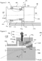
- Fig. 3 shows a schematic bearing arrangement 114 according to an embodiment of the invention.
- the bearing arrangement 114 is generally of the type as described with reference to Fig. 2 above.
- the bearing arrangement 114 has a bearing housing 126, a rotor shaft 124 (corresponding to a rotating component), a first roller bearing 128 and a second roller bearing 130 (not shown for the sake of overview).
- the bearing arrangement 114 has a longitudinal axis 116 and the rotor shaft 124 rotates around a rotational axis R.
- the bearing housing 126 supports the first and the second roller bearings 128 and 130.
- the first and the second roller bearings 128 and 130 support the rotor shaft 124.
- the first roller bearing 128 and the second roller bearing 130 are tapered roller bearings and arranged in the so-called "O"-arrangement.
- the first roller bearing 128 is arranged at the rear side 120 (generator side or gearbox side). At the rear side, the rotor shaft 124 is connected to a gearbox (not shown).
- the first roller bearing 128 comprises a first bearing inner ring 140, a first bearing outer ring 142 and a plurality of rolling elements 143 arranged and supported between the first bearing inner ring 140 and the first bearing outer ring 142.
- the bearing arrangement 114 is operated such that a rotation of the rotor 108 drives the rotor shaft 124.
- the rotation of the rotor shaft 124 is transferred to the gearbox, via which a generator is driven to generate electrical energy.
- the bearing arrangement 114 of Fig. 3 is generally pretensioned as described above and in accordance with Fig. 2 .
- the first roller bearing 128, the second roller bearing 130, the rotor shaft 124 and the bearing housing 126 are designed and arranged to form a pretension circuit 138.
- the first bearing outer ring 142 can be axially moved.
- the bearing arrangement 114 comprises an actuation device 144 and a pretension ring 146.
- the actuation device 144 comprises a connecting element 148 and an actuation element 150.
- the connecting element 148 is a lever or a shaft.
- the actuation element 150 is a hydraulic cylinder.
- the actuation device 144 essentially extends in a radial direction with respect to the rotational axis (R).
- the actuation device 144 is mechanically and fixedly connected to the pretension ring 146, e.g. via a screw connection or a form-fit connection.
- the connecting element 148 extends radially through an opening 152 of the bearing housing 126.
- the pretension ring 146 is a ring-shaped element, e.g. washer-like, and is arranged withing the bearing housing 126.
- the pretension ring 146 surrounds the rotor shaft 124.
- the pretension ring 146 is provided between the bearing housing 126 and the first bearing outer ring 142 along the axial direction.
- the pretension ring 146 is in threaded engagement with the bearing housing 126.
- the pretension ring 146 comprises an outer threaded surface 154.
- the pretension ring 146 comprises an outer surface with an outer thread.
- the bearing housing 126 comprises an inner threaded surface 156.
- the bearing housing 126 comprises an inner surface with an inner thread.
- the actuation device 144 Upon actuation the actuation device 144 an axial movement of the first bearing outer ring 142 is caused. More precisely, the actuation of the actuating element 150 turns the connecting element 148 around the rotational axis R. Due to the connection to the pretension ring 146, the movement of the connecting element 148 directly turns the pretension ring 146 circumferentially around the rotational axis R. Thus, torque is applied to the pretension ring 146. Due to the threaded connection, the turning of the pretension ring 146 causes an axial movement of the pretension ring 146. Thus, an axial force F is exerted on the first bearing outer ring 142, due to direct contact of the pretension ring 146 and the first bearing outer ring 142. The pretension ring 146 is configured to distribute the load evenly on the first bearing outer ring 142.
- the pretension ring 146 is actuated (turned) such that it is moved (further) against the first bearing outer ring 142 (towards the right in Fig. 3 ). This causes an axial movement/displacement of the first bearing outer ring 142 and thus impacts the pretension circuit 138. The pretension of the bearing arrangement 114 is thus adjusted.
- the pretension ring 146 can be actuated such that it is moved away from the first bearing outer ring 142 (towards the left in Fig. 3 ), meaning that the pretension can be reduced.
- the opening 152 in the bearing housing 126 is slit-like and extends circumferentially over a portion of the bearing housing 126 around the rotational axis R.
- the dimensions of the opening 152 are larger than the width of the connecting element 148, such that the connecting element 148 can be moved within the opening 152 along the circumferential direction.
- the opening 152 may allow a turning of the connecting element 148 within a range of 10° along the circumferential direction.
- the actuation device 144 is arranged between the first roller bearing 128 and the second roller bearing.
- the actuation device 144 is easily accessible from outside 158 of the bearing arrangement 114.
- For adjustment of the pretension it is thus not necessary to gain access from the rear (gearbox) side 120, which is particularly problematic after the bearing arrangement 114 has been installed in the wind turbine 100 and/or during operation of the wind turbine 100.
- a very precise adjustment of the pretension is possible by the thread of the pretension ring 146.
- a fine thread is used to allow fine tuning of the pretension, i.e. only fractions of a mm.
- Figure 4 shows a further embodiment of the invention, which differs regarding the actuation device 144 and the adjustment of the pretension.
- the above description of the features similarly applies, unless otherwise stated below.
- not all reference signs may necessarily be reproduced in the figures and described again.
- the pretension ring 146 is provided between the bearing housing 126 and the first bearing outer ring 142 mainly along the radial direction.
- the pretension ring 146 comprises a shoulder 162, which partially surrounds the first bearing outer ring 142 and thereby forms a form-fit engagement in the axial direction with respect to the rotational axis R.
- the axial movement of the pretension ring 146 causes the axial movement of the first bearing outer ring 142 due to the engagement of the shoulder 162.
- FIG. 5 shows a further embodiment of the invention, which differs regarding the actuation device 144 and the adjustment of the pretension.
- the above description of the features similarly applies, unless otherwise stated below.
- not all reference signs may necessarily be reproduced in the figures and described again.
- the embodiment according to Fig. 5 essentially resembles the embodiment according to Fig. 3 , wherein further a force transfer element 164 is arranged between the pretension ring 146 and the first bearing outer ring 142.
- the force transfer element 164 is arranged axially between the respective components with respect to the rotational axis R.
- the force transfer element 156 is a ring-shaped member extending circumferentially around the rotational axis R.
- the force transfer element 156 is washer-like and can also be called a pressure ring.
- the force transfer element 156 is axially moveable. Since the force transfer element 156 is moveable parallel to the rotational axis R, the force F generated by actuating the pretension ring 146 is transferred onto the first bearing outer ring 142.
- FIG. 6 shows a further embodiment of the invention, which differs regarding the actuation device 144 and the adjustment of the pretension.
- the above description of the features similarly applies, unless otherwise stated below.
- not all reference signs may necessarily be reproduced in the figures and described again.
- the embodiment according to Fig. 6 essentially resembles the embodiment according to Fig. 4 , wherein again a force transfer element 164 is provided.
- the pretension ring 146 and the force transfer element 164 are arranged and designed such that these elements form together a contact interface 166 which is inclined with regard to the rotational axis R.
- the contact interface 166 is a contact area running inclined with respect to extension direction of the actuation element 144, which is radial.
- the force transfer element 164 and the pretension ring 146 contact each other in a wedge-shaped manner.
- the transfer element 164 comprises an optional inner shoulder 168 (also named step or ring section) to fix the first bearing outer ring 142 in axial direction, in particular against the bearing housing 126.
- the pretension ring 146 is turned, wherein due to the inclined contact interface 166 a generated force is redirected such that the force transfer element 156 radially transfers a resulting force F onto the first bearing outer ring 142 in order to move / displace the first bearing outer ring 142 radially.
- the pretension of the bearing arrangement 114 can be adjusted, analogously as described above.
- the embodiment thus provides for an adjustment of pretension by radially compressing the force transfer element 164 and thus the first bearing outer ring 142.
- the axial position of the first bearing outer ring 142 is preferably stationarily fixed.
- a fine tuning of pretension is provided by the wedged contact surface 166.
- the force transfer element 164 could be formed in segments, as one-piece ring of large diameter may lead to undesired deformations due to their own weight. Furthermore, the segmenting of the force transfer element 164 could provide a better handling. The segments could be spaced from one another. The gap width between two neighboring segments would then be dependent on the deformation of the segments in circumferential direction. Alternatively, the segments could be connected to one another via flexible connectors.
- the actuation device 144 is constantly connected to the pretension ring 146.
- the actuation device 144 may only be connected to the pretension ring 146 when the actuation device 144 is meant to be operated for adjusting the pretension.
- the actuation device 144 extends radially, at least the connecting element 148.
- an angle ⁇ with respect to the rotational axis R is 90°.
- an angled orientation of the actuation device 144 is also conceivable.
- the actuation device 144 may be oriented radially, axially, or oblique with respect to the rotational axis R.
- one or more abutment elements are provided at the bearing housing 126 in the region of the actuation device 144 or at the actuation device 144 itself, so that actuation of the actuation device is geometrically limited.
- the movement, e.g. turning, of the actuation device 144 is geometrically limited.
- the opening 152 defines or forms the abutment element, e.g. by its surrounding walls. The opening 152 thus automatically limits the movement, e.g. the turn angle, of the actuation device 144, in particular the connecting element 148.
- a described actuation device 144 may comprise a sensor 160, as exemplarily indicated in Fig. 3 .
- the sensor 160 is, for example, a strain gauge and configured to measure a parameter representative for a pretensioning state of the bearing arrangement 114. Based on the sensor's measurement, the pretension of the bearing arrangement 114 is adjusted as described above, which can either be manually or automatically. Additionally or alternatively, the sensor 160 is provided at the pretension ring 146.
- an adjustment device e.g. a screw, grub screw, nut, pretension ring, hydraulic device
- the adjustment device is provided to act on the first bearing inner ring 140 as described above (see for example the pretension ring 136 according to Fig. 2 ).
- several adjustment device can be provided.
- actuation device 144 Although reference is made to only one actuation device 144, a plurality of actuation devices 144 can be provided, as described in the introductory section. For example, two actuation devices 144 being distant to each other about 180° along the circumference of the bearing housing 126, are provided, each of them being connected to the pretension ring 146 as described above. Thus, for example, moving of the pretension ring 146 and thus adjusting the pretension is made easier.
- the described embodiments are not restricted to special details of the bearings and/or the bearing arrangement, for example concerning the design of the shaft 124 or the design of the bearing housing 126.
- the provision of one or more actuation devices 144 which allow for easy adjustment of the bearing pretension from outside the bearing housing is essential, even after an initial installation in the wind turbine or during operation of the wind turbine.
Landscapes
- Engineering & Computer Science (AREA)
- General Engineering & Computer Science (AREA)
- Mechanical Engineering (AREA)
- Life Sciences & Earth Sciences (AREA)
- Sustainable Development (AREA)
- Sustainable Energy (AREA)
- Chemical & Material Sciences (AREA)
- Combustion & Propulsion (AREA)
- Mounting Of Bearings Or Others (AREA)
Priority Applications (2)
| Application Number | Priority Date | Filing Date | Title |
|---|---|---|---|
| EP23178381.2A EP4474663A1 (de) | 2023-06-09 | 2023-06-09 | Lageranordnung für ein rotierendes bauteil einer windenergieanlage |
| US18/737,792 US20240410420A1 (en) | 2023-06-09 | 2024-06-07 | Bearing arrangement for a rotating component of a wind turbine |
Applications Claiming Priority (1)
| Application Number | Priority Date | Filing Date | Title |
|---|---|---|---|
| EP23178381.2A EP4474663A1 (de) | 2023-06-09 | 2023-06-09 | Lageranordnung für ein rotierendes bauteil einer windenergieanlage |
Publications (1)
| Publication Number | Publication Date |
|---|---|
| EP4474663A1 true EP4474663A1 (de) | 2024-12-11 |
Family
ID=86760141
Family Applications (1)
| Application Number | Title | Priority Date | Filing Date |
|---|---|---|---|
| EP23178381.2A Pending EP4474663A1 (de) | 2023-06-09 | 2023-06-09 | Lageranordnung für ein rotierendes bauteil einer windenergieanlage |
Country Status (2)
| Country | Link |
|---|---|
| US (1) | US20240410420A1 (de) |
| EP (1) | EP4474663A1 (de) |
Citations (8)
| Publication number | Priority date | Publication date | Assignee | Title |
|---|---|---|---|---|
| GB2172939A (en) * | 1985-03-25 | 1986-10-01 | Torrington Co | Variable preload bearing assembly |
| JP2006177268A (ja) * | 2004-12-24 | 2006-07-06 | Nsk Ltd | 風力発電装置用回転支持装置 |
| EP1745221A2 (de) * | 2004-05-07 | 2007-01-24 | The Timken Company | Festlageranordnung für windturbinengetriebewelle |
| EP2290250A2 (de) * | 2009-08-12 | 2011-03-02 | Romax Technology Limited | Lagerpatrone |
| WO2011033256A1 (en) * | 2009-09-15 | 2011-03-24 | Ricardo Uk Ltd. | Bearing for wind turbine |
| US20140199004A1 (en) * | 2012-01-16 | 2014-07-17 | Romax Technology Limited | Bearing Retainer |
| WO2017147766A1 (en) * | 2016-03-01 | 2017-09-08 | The Timken Company | Apparatus and method for preloading bearing assemblies |
| WO2023045294A1 (zh) * | 2021-09-26 | 2023-03-30 | 新疆金风科技股份有限公司 | 用于轴系的支撑装置及风力发电机组 |
Family Cites Families (3)
| Publication number | Priority date | Publication date | Assignee | Title |
|---|---|---|---|---|
| US4571097A (en) * | 1985-01-24 | 1986-02-18 | The Timken Company | Tapered roller bearing with pressurized rib ring |
| DE102013226552B3 (de) * | 2013-12-19 | 2015-05-13 | Aktiebolaget Skf | Montagevorrichtung für ein Wälzlager |
| CN111919043B (zh) * | 2018-02-07 | 2022-09-20 | 铁姆肯公司 | 用于在预负载操作期间定位轴承组件的滚动元件的组装工具和方法 |
-
2023
- 2023-06-09 EP EP23178381.2A patent/EP4474663A1/de active Pending
-
2024
- 2024-06-07 US US18/737,792 patent/US20240410420A1/en active Pending
Patent Citations (8)
| Publication number | Priority date | Publication date | Assignee | Title |
|---|---|---|---|---|
| GB2172939A (en) * | 1985-03-25 | 1986-10-01 | Torrington Co | Variable preload bearing assembly |
| EP1745221A2 (de) * | 2004-05-07 | 2007-01-24 | The Timken Company | Festlageranordnung für windturbinengetriebewelle |
| JP2006177268A (ja) * | 2004-12-24 | 2006-07-06 | Nsk Ltd | 風力発電装置用回転支持装置 |
| EP2290250A2 (de) * | 2009-08-12 | 2011-03-02 | Romax Technology Limited | Lagerpatrone |
| WO2011033256A1 (en) * | 2009-09-15 | 2011-03-24 | Ricardo Uk Ltd. | Bearing for wind turbine |
| US20140199004A1 (en) * | 2012-01-16 | 2014-07-17 | Romax Technology Limited | Bearing Retainer |
| WO2017147766A1 (en) * | 2016-03-01 | 2017-09-08 | The Timken Company | Apparatus and method for preloading bearing assemblies |
| WO2023045294A1 (zh) * | 2021-09-26 | 2023-03-30 | 新疆金风科技股份有限公司 | 用于轴系的支撑装置及风力发电机组 |
Also Published As
| Publication number | Publication date |
|---|---|
| US20240410420A1 (en) | 2024-12-12 |
Similar Documents
| Publication | Publication Date | Title |
|---|---|---|
| US9284949B2 (en) | Bearing arrangement of a wind turbine and method for adjusting the preload of a bearing arrangement | |
| US6866423B2 (en) | Roller bearing | |
| DK2553264T3 (en) | Windmill | |
| EP2372151B1 (de) | Windturbine | |
| RU2523515C2 (ru) | Устройство с подвижным силовым цилиндром для управления ориентацией лопатками вентилятора турбовинтового двигателя | |
| US9011010B2 (en) | Hybrid wind turbine blade bearing | |
| EP1995453B1 (de) | Vorrichtung zum Einstellen des Einstellwinkels eines Rotorblattes einer Windenergieanlage | |
| WO2012146751A2 (en) | Pitch drive system and method | |
| JP2010508470A (ja) | シール取付装置 | |
| EP2481926A1 (de) | Phasenänderungsverfahren und Phasenänderungsvorrichtung für ein Schaufellager | |
| US10495070B2 (en) | Gearbox for a wind turbine | |
| RU2527919C2 (ru) | Устройство регулирования шага лопастей ветрогенератора | |
| EP1995454B1 (de) | Vorrichtung zum Einstellen des Neigungswinkels eines Rotorblattes einer Windenergieanlage | |
| EP4474663A1 (de) | Lageranordnung für ein rotierendes bauteil einer windenergieanlage | |
| DE102020133993A1 (de) | Lageranordnung für ein rotierendes Bauteil einer Windenergieanlage sowie Windenergieanlage | |
| CA2114724C (en) | Compensation for kinematic foreshortening effect in pitch control system for rotary wing aircraft | |
| EP4474642A1 (de) | Lageranordnung für ein rotierendes bauteil einer windenergieanlage | |
| EP4575251A1 (de) | Lageranordnung für ein rotierendes bauteil einer windenergieanlage | |
| EP2531725B1 (de) | Hybridlager für ein Windturbinenblatt | |
| CN120712406A (zh) | 用于降低和/或提升风力涡轮机的转子叶片的方法以及用于维修风力涡轮机的转子叶片的方法 | |
| CN110701006B (zh) | 偏航轴承布置结构 | |
| WO2025242256A1 (de) | Gleitlageranordnung zum gleitlagern einer rotorwelle einer windenergieanlage | |
| CN121760888A (zh) | 传动装置、传动系统、风力发电机组及维护方法 | |
| Poll et al. | 2.6 Monitoring of Mechanical Components (WP 6) |
Legal Events
| Date | Code | Title | Description |
|---|---|---|---|
| PUAI | Public reference made under article 153(3) epc to a published international application that has entered the european phase |
Free format text: ORIGINAL CODE: 0009012 |
|
| STAA | Information on the status of an ep patent application or granted ep patent |
Free format text: STATUS: THE APPLICATION HAS BEEN PUBLISHED |
|
| AK | Designated contracting states |
Kind code of ref document: A1 Designated state(s): AL AT BE BG CH CY CZ DE DK EE ES FI FR GB GR HR HU IE IS IT LI LT LU LV MC ME MK MT NL NO PL PT RO RS SE SI SK SM TR |
|
| STAA | Information on the status of an ep patent application or granted ep patent |
Free format text: STATUS: REQUEST FOR EXAMINATION WAS MADE |
|
| 17P | Request for examination filed |
Effective date: 20250604 |
|
| STAA | Information on the status of an ep patent application or granted ep patent |
Free format text: STATUS: EXAMINATION IS IN PROGRESS |
|
| 17Q | First examination report despatched |
Effective date: 20260109 |