EP4474809A1 - Système de détection ultrasonore à réseau à commande de phase - Google Patents
Système de détection ultrasonore à réseau à commande de phase Download PDFInfo
- Publication number
- EP4474809A1 EP4474809A1 EP23275087.7A EP23275087A EP4474809A1 EP 4474809 A1 EP4474809 A1 EP 4474809A1 EP 23275087 A EP23275087 A EP 23275087A EP 4474809 A1 EP4474809 A1 EP 4474809A1
- Authority
- EP
- European Patent Office
- Prior art keywords
- phased array
- array ultrasonic
- images
- weld
- morphological
- Prior art date
- Legal status (The legal status is an assumption and is not a legal conclusion. Google has not performed a legal analysis and makes no representation as to the accuracy of the status listed.)
- Pending
Links
- 239000000523 sample Substances 0.000 claims abstract description 105
- 238000011156 evaluation Methods 0.000 claims abstract description 18
- 230000001066 destructive effect Effects 0.000 claims abstract description 17
- 230000000877 morphologic effect Effects 0.000 claims description 81
- 238000000034 method Methods 0.000 claims description 36
- 238000006073 displacement reaction Methods 0.000 claims description 15
- 238000005314 correlation function Methods 0.000 claims description 13
- 230000010339 dilation Effects 0.000 claims description 13
- 230000003628 erosive effect Effects 0.000 claims description 10
- 239000000463 material Substances 0.000 description 25
- 238000007689 inspection Methods 0.000 description 19
- 238000005259 measurement Methods 0.000 description 11
- 238000012545 processing Methods 0.000 description 11
- 230000006870 function Effects 0.000 description 8
- 230000004807 localization Effects 0.000 description 6
- 230000008569 process Effects 0.000 description 6
- 230000007547 defect Effects 0.000 description 5
- 230000008901 benefit Effects 0.000 description 4
- 238000004519 manufacturing process Methods 0.000 description 4
- 238000003466 welding Methods 0.000 description 4
- 238000001816 cooling Methods 0.000 description 3
- 229910001338 liquidmetal Inorganic materials 0.000 description 3
- 229910000746 Structural steel Inorganic materials 0.000 description 2
- 239000003086 colorant Substances 0.000 description 2
- 238000011161 development Methods 0.000 description 2
- 230000018109 developmental process Effects 0.000 description 2
- 238000010586 diagram Methods 0.000 description 2
- 239000012636 effector Substances 0.000 description 2
- 230000036541 health Effects 0.000 description 2
- 230000007774 longterm Effects 0.000 description 2
- 238000012360 testing method Methods 0.000 description 2
- 238000012549 training Methods 0.000 description 2
- 229910000975 Carbon steel Inorganic materials 0.000 description 1
- 229910000831 Steel Inorganic materials 0.000 description 1
- 238000003491 array Methods 0.000 description 1
- 238000013473 artificial intelligence Methods 0.000 description 1
- 230000009286 beneficial effect Effects 0.000 description 1
- 239000010962 carbon steel Substances 0.000 description 1
- 238000003486 chemical etching Methods 0.000 description 1
- 230000000295 complement effect Effects 0.000 description 1
- 238000005336 cracking Methods 0.000 description 1
- 238000005520 cutting process Methods 0.000 description 1
- 238000013135 deep learning Methods 0.000 description 1
- 230000007123 defense Effects 0.000 description 1
- 238000013461 design Methods 0.000 description 1
- 238000001514 detection method Methods 0.000 description 1
- 230000000916 dilatatory effect Effects 0.000 description 1
- 238000005516 engineering process Methods 0.000 description 1
- 230000004927 fusion Effects 0.000 description 1
- 231100001261 hazardous Toxicity 0.000 description 1
- 238000010438 heat treatment Methods 0.000 description 1
- 238000003384 imaging method Methods 0.000 description 1
- 238000012625 in-situ measurement Methods 0.000 description 1
- 238000011065 in-situ storage Methods 0.000 description 1
- 238000011835 investigation Methods 0.000 description 1
- 239000007788 liquid Substances 0.000 description 1
- 239000006249 magnetic particle Substances 0.000 description 1
- 230000007246 mechanism Effects 0.000 description 1
- 238000005457 optimization Methods 0.000 description 1
- 230000002085 persistent effect Effects 0.000 description 1
- 238000005498 polishing Methods 0.000 description 1
- 238000012805 post-processing Methods 0.000 description 1
- 238000002601 radiography Methods 0.000 description 1
- 238000002407 reforming Methods 0.000 description 1
- 230000003252 repetitive effect Effects 0.000 description 1
- 230000004044 response Effects 0.000 description 1
- 230000011218 segmentation Effects 0.000 description 1
- 230000035945 sensitivity Effects 0.000 description 1
- 238000000926 separation method Methods 0.000 description 1
- 239000007787 solid Substances 0.000 description 1
- 238000007711 solidification Methods 0.000 description 1
- 230000008023 solidification Effects 0.000 description 1
- 239000010959 steel Substances 0.000 description 1
- 238000003860 storage Methods 0.000 description 1
- 238000001931 thermography Methods 0.000 description 1
- 238000011179 visual inspection Methods 0.000 description 1
Images




Classifications
-
- G—PHYSICS
- G01—MEASURING; TESTING
- G01N—INVESTIGATING OR ANALYSING MATERIALS BY DETERMINING THEIR CHEMICAL OR PHYSICAL PROPERTIES
- G01N29/00—Investigating or analysing materials by the use of ultrasonic, sonic or infrasonic waves; Visualisation of the interior of objects by transmitting ultrasonic or sonic waves through the object
- G01N29/22—Details, e.g. general constructional or apparatus details
- G01N29/26—Arrangements for orientation or scanning by relative movement of the head and the sensor
- G01N29/262—Arrangements for orientation or scanning by relative movement of the head and the sensor by electronic orientation or focusing, e.g. with phased arrays
-
- G—PHYSICS
- G01—MEASURING; TESTING
- G01N—INVESTIGATING OR ANALYSING MATERIALS BY DETERMINING THEIR CHEMICAL OR PHYSICAL PROPERTIES
- G01N29/00—Investigating or analysing materials by the use of ultrasonic, sonic or infrasonic waves; Visualisation of the interior of objects by transmitting ultrasonic or sonic waves through the object
- G01N29/04—Analysing solids
- G01N29/043—Analysing solids in the interior, e.g. by shear waves
-
- G—PHYSICS
- G01—MEASURING; TESTING
- G01N—INVESTIGATING OR ANALYSING MATERIALS BY DETERMINING THEIR CHEMICAL OR PHYSICAL PROPERTIES
- G01N29/00—Investigating or analysing materials by the use of ultrasonic, sonic or infrasonic waves; Visualisation of the interior of objects by transmitting ultrasonic or sonic waves through the object
- G01N29/04—Analysing solids
- G01N29/06—Visualisation of the interior, e.g. acoustic microscopy
- G01N29/0609—Display arrangements, e.g. colour displays
-
- G—PHYSICS
- G01—MEASURING; TESTING
- G01N—INVESTIGATING OR ANALYSING MATERIALS BY DETERMINING THEIR CHEMICAL OR PHYSICAL PROPERTIES
- G01N29/00—Investigating or analysing materials by the use of ultrasonic, sonic or infrasonic waves; Visualisation of the interior of objects by transmitting ultrasonic or sonic waves through the object
- G01N29/04—Analysing solids
- G01N29/06—Visualisation of the interior, e.g. acoustic microscopy
- G01N29/0654—Imaging
-
- G—PHYSICS
- G01—MEASURING; TESTING
- G01N—INVESTIGATING OR ANALYSING MATERIALS BY DETERMINING THEIR CHEMICAL OR PHYSICAL PROPERTIES
- G01N29/00—Investigating or analysing materials by the use of ultrasonic, sonic or infrasonic waves; Visualisation of the interior of objects by transmitting ultrasonic or sonic waves through the object
- G01N29/22—Details, e.g. general constructional or apparatus details
- G01N29/26—Arrangements for orientation or scanning by relative movement of the head and the sensor
- G01N29/265—Arrangements for orientation or scanning by relative movement of the head and the sensor by moving the sensor relative to a stationary material
-
- G—PHYSICS
- G01—MEASURING; TESTING
- G01N—INVESTIGATING OR ANALYSING MATERIALS BY DETERMINING THEIR CHEMICAL OR PHYSICAL PROPERTIES
- G01N2291/00—Indexing codes associated with group G01N29/00
- G01N2291/10—Number of transducers
- G01N2291/106—Number of transducers one or more transducer arrays
-
- G—PHYSICS
- G01—MEASURING; TESTING
- G01N—INVESTIGATING OR ANALYSING MATERIALS BY DETERMINING THEIR CHEMICAL OR PHYSICAL PROPERTIES
- G01N2291/00—Indexing codes associated with group G01N29/00
- G01N2291/26—Scanned objects
- G01N2291/267—Welds
Definitions
- Non-destructive evaluation of welds of components can be performed using a phased array ultrasonic probe.
- the phased array ultrasonic probe typically includes a plurality of ultrasonic transmitters and receivers to transmit ultrasonic signals and receive their reflections.
- the weld can be evaluated by generating images using the ultrasonic reflections if the transmitted signal is incident on the weld itself. It is therefore necessary to find an initial position for the phased array ultrasonic probe that will enable the probe to detect the weld.
- Embodiments of the present invention are intended to improve on the prior art.
- a phased array ultrasonic sensing system comprising: a phased array ultrasonic probe for sending and receiving phased array ultrasonic signals; a processor configured to generate phased array ultrasonic images using the received phased array ultrasonic signals; a display for displaying direction indications to guide a user in moving the phased array ultrasonic probe during a non-destructive evaluation of a weld of a component; and a controller configured to control the display to display the direction indications to guide the user in moving the phased array ultrasonic probe based on a position of the weld in the generated phased array ultrasonic images.
- the controller being configured to compare the morphological images to the weld mask comprises the controller being configured to determine a similarity between the morphological images and the weld mask as a function of displacement between a weld in the morphological image and the weld in the weld mask.
- the controller being configured to determine a similarity between the morphological images and the weld mask as a function of displacement between a weld in the morphological images and the weld in the mask comprises the controller being configured to calculate a cross-correlation function between the morphological images and the weld mask.
- the controller being configured to control the display to display the direction indications to guide the user to reduce a displacement between a position of the phased array ultrasonic probe and an ideal position of the phased array ultrasonic probe based on the comparison comprises the controller being configured to determine a position of maximum cross-correlation in the morphological images and to measure a distance between the position of maximum cross-correlation and the ideal weld position.
- the generating the morphological images comprises the controller being configured to apply a plurality of steps including: normalising the phased array ultrasonic images to convert the phased array ultrasonic images into grayscale images; thresholding, using a threshold value, the grayscale images to convert the grayscale images into binary images; applying morphological opening to the binary images; applying an erosion step to the morphologically opened binary images to form a single binary object; applying dilation to the single binary object until a number of pixels is constant; and then multiplying the dilated single binary object with the thresholded binary image.
- the applying morphological opening to the binary images comprises applying a 3 x 3 structuring element, and optionally applying the structuring element horizontally and then vertically.
- the applying image dilation to the binary images comprises applying a 3 x 50 structuring element.
- the controller being configured to generate the morphological images comprises the controller being configured to apply a further plurality of steps after applying the plurality of steps, the further plurality of steps including: normalising the phased array ultrasonic images to convert the phased array ultrasonic images into grayscale images; thresholding, using a different threshold value than the threshold value of the plurality of step, the grayscale images to convert the grayscale images into binary imaged; applying morphological opening to the binary images; applying an erosion step to the morphologically opened binary images to form a single binary object; applying dilation to the single binary object until a number of pixels is constant; and then multiplying the dilated single binary object with the thresholded binary image.
- the controller being configured to generate the morphological images comprises the controller being configured to combine the plurality of steps with the further plurality of steps.
- the direction indications include a plurality of coloured lights, and/or wherein the direction indications include a plurality of arrows indicating a direction to move the phased array ultrasonic probe.
- a method of performing non-destructive evaluation of a weld of a component using a phased array ultrasonic probe comprising: sending and receiving, using a phased array ultrasonic probe, phased array ultrasonic signals; generating phased array ultrasonic images using the received phased array ultrasonic signals; displaying, by a display, direction indications to guide a user of the phased array ultrasonic probe in moving the phase array ultrasonic probe based on a position of the weld in the generated phased array ultrasonic images.
- the displaying, by a display, direction indications to guide a user of the phased array ultrasonic probe in moving the phase array ultrasonic probe based on a position of the weld in the generate images comprises: generating morphological images from the generated phased array ultrasonic images; comparing the morphological images to a weld mask including an ideal weld position relative to the phased array ultrasonic probe; and displaying the direction indications to guide the user to reduce a displacement between a position of the phased array ultrasonic probe and an ideal position of the phased array ultrasonic probe based on the comparison.
- the comparing the morphological images to the weld mask comprises the controller being configured to determine a similarity between the morphological images and the weld mask as a function of displacement between a weld in the morphological image and the weld in the weld mask.
- the determining a similarity between the morphological images and the weld mask as a function of displacement between a weld in the morphological image and the weld in the mask comprises calculating a cross-correlation function between the morphological images and the weld mask.
- the calculating a cross-correlation function between the morphological images and the weld mask comprises parsing the weld mask along the morphological images in a direction perpendicular to the weld and calculating the cross-correlation function at each increment of the morphological images that are parsed.
- the displaying the direction indications to guide the user to reduce a displacement between a position of the phased array ultrasonic probe and an ideal position of the phased array ultrasonic probe based on the comparison comprises determining a position of maximum cross-correlation in the morphological images and measuring a distance between the position of maximum cross-correlation and the ideal weld position.
- the applying morphological opening to the binary images comprises applying first a 3 x 3 structuring element, and optionally applying the structuring element horizontally and then vertically.
- the applying image dilation to the binary images comprises applying a 3 x 50 structuring element.
- the generating the morphological images applying a further plurality of steps after applying the plurality of steps including: normalising the phased array ultrasonic images to convert the phased array ultrasonic images into grayscale images; thresholding, using a different threshold value than the threshold value of the plurality of step, the grayscale images to convert the grayscale images into binary imaged; applying morphological opening to the binary images; applying an erosion step to the morphologically opened binary images to form a single binary object; applying dilation to the single binary object until a number of pixels is constant; and then multiplying the dilated single binary object with the thresholded binary image.
- the generating the morphological images comprises combining the plurality of steps with the further plurality of steps.
- the direction indications include a plurality of coloured lights, and/or wherein the direction indications include a plurality of arrows indicating a direction to move the phased array ultrasonic probe.
- the present disclosure relates generally to an image processing-based localization system for remote non-destructive evaluation of welds within industrial assets.
- Manual ultrasonic inspection of large-scale structures is often repetitive and time consuming and benefits greatly from robotic support, however, these systems are often fixed to a single purpose, lack self-awareness, and can be limited to simple geometry.
- surface features for automated tracking such as the laser profiling of a weld cap.
- a more sensitive method is required.
- the proposed system utilizes information already available to a non-destructive inspector in the form of live phased array ultrasonic images to estimate the location of the weld using non-surface, volumetric data.
- Data is captured using a 64 element, 10 MHz phased array probe mounted to the end-effector of a small robotic manipulator which increases the scope of applications due to its heightened flexibility.
- Morphological operations are applied to the ultrasonic data to reduce the noise apparent from regions of parent material and promote the data reflected from grain boundaries within the weld material.
- image processing techniques it is possible to predict the position of a weld under inspection with a mean positional error of 0.8 mm. From this study, the localization system is to be embedded within a remote system for extensive data acquisition of welds on large structures.
- the system includes a robot 10 is used to perform non-destructive evaluation of a component 12.
- the robot 10 includes a body mounted to the component 12, an actuator 14 for moving the phased array ultrasonic probe during non-destructive evaluation, a controller 16 configured to control the actuator to move the phased array ultrasonic probe based on a position of the weld in the generated phased array ultrasonic images to maintain a predetermined distance from the weld during the non-destructive evaluation.
- the actuator 14 may be configured to move the probe 22 itself, e.g. by moving the arm, or may be configured to move the robot 10.
- the robot 10 also includes a processor 18, an arm 20, a phased array ultrasonic probe 22.
- the component 12 includes a first part 24, a second part 26, and a weld 28 connecting the first part to the second part.
- NDE Non-Destructive Evaluation
- NDE is routinely used in the manufacture of maritime vehicles due to the criticality of ensuring a sound structural condition for extending the working life of these assets and to assure the safety of those onboard.
- NDE techniques exist and are utilized on site to fully assess the status of these vehicles, including: visual inspection, magnetic particle inspection, dye penetrant, ultrasonic testing (UT), electromagnetic based methods, thermography, and radiography.
- UT is the method of choice due its non-hazardous application, its ability to perform volumetric inspections, and increased detection capabilities.
- UT inspection often uses the pulse-echo technique which involves using the probe 32 first as a transmitter to generate a wave 34 into the material 35, then as a receiver to detect any reflections 36.
- PAUT Phased Array Ultrasonic Testing
- the probe 22 of Figure 1 is a phased array ultrasonic probe using the techniques shown in Figure 3 .
- PAUT For the investigation of butt welded structural steel plates, the use of PAUT allows an inspector to capture data faster than previously possible with single element transducers. They can be further supported through robotic systems scaling from large fixed setups to smaller teleoperated ariel and surface dwelling solutions.
- Large scale industrial settings typically see the implementation of robotic crawlers to conduct remote inspection in unreachable or confined areas to reduce the time to inspect the material and improve the health and safety of the inspector.
- Current on-the-market products are often built for a specific purpose and maintain the need for an operator to control and position the crawler appropriately, although weld profile trackers are available, they require the presence of a physical weld cap to function. Situations where a weld cap has been removed through grinding therefore possess a problem for such systems.
- the next level of remote inspection lies in the advancement of crawler autonomy and their alignment with NDE 4.0, improving their situational awareness.
- Image processing is advantageous in this scenario as it can be applied to the data already available to the NDE inspector and no additional sensors require housing on the remote base. This also minimizes the cost associated with building the system and any additional time investment configuring and integrating additional sensors.
- Image processing techniques have been used with NDE data in differing capacities but this has predominantly been for the identification and classification of defects for ultrasonic and other NDE methods rather than weld material.
- weld segmentation does exist from Provencal and Laperrière who utilized artificial intelligence (AI) with a fully convolutional network and deep learning to train a model to segment both defects and weld geometry. Although accurate and requiring minimal PAUT measurements to train the model, it is an example of an AI-generated rule-based system which will see implementation, e.g.
- the main contributions of this disclosure include: the implementation of image processing for live in-situ localization of structural steel welds; the development of a human-generated rule-based decision-making system for automated data acquisition; and advancements towards general-purpose multi-usage inspection solutions.
- a high strength NQ grade steel butt weld sample is assessed ultrasonically.
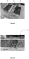
- a component, or a sample is a 300 x 200 x 43 mm section of plate with a double-V weld running through its centre and the weld cap removed through a series of grinding and polishing.
- a weld after its cap has been removed may be termed a "dressed-weld".
- the sample retains no discernible surface features visible to the naked eye or to a sensor due to the cap removal.
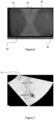
- FIG. 7 an example of a sectorial scan attained from the sample is given in using a ZETEC phased array probe in pulse-echo mode with a 55° shear wave wedge.
- the probe details and software configuration for capturing data are shown below in Table 1.
- a higher frequency probe and the use of shear waves is beneficial for the application due to its increased resolution and sensitivity to signals from the weld material.
- the software settings also defined within the table were selected based on an optimization study ran to maximize the weld response signal to 4.75 dB when compared to the surrounding background noise.
- the sectorial scan from Figure 7 may be considered to be a phased array ultrasonic image 37 generated by the processor 18 ( Figure 1 ) using the received phased array ultrasonic signals.
- the actual mechanisms for returning an ultrasonic signal lie in a difference of microstructure between weld and parent material.
- liquid metal is deposited between two plates forming a liquid pool which cools and solidifies as a welding torch passes across the sample.
- the liquid metal forms new grains in a unique columnar structure in the direction of the heat gradient.
- the sample assessed here is also a multi-pass weld meaning the reforming process is repeated during every pass thus a new microstructure is produced as seen in Figure 6 . Faint signs of directionality are apparent but are limited in size due to the nature of carbon steel during the cooling period after welding.
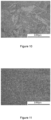
- FIG. 8 Microscopic images of the unique regions are displayed across Figure 8, Figure 9 , Figure 10, and Figure 10 .
- the parent material of Figure 8 exhibits a fine equiaxial grain structure.
- the structure of the weld material seen in Figure 9 is more undefined but its previously stated slight directionality and anisotropy are likely sources of the signal seen in Figure 7 .
- HAZ 1 is formed through the extreme heating of parent material directly next to the weld pool but does not itself liquify. The high-temperature cooling that follows creates the larger, coarse, anisotropic grains of Figure 10 . This particular structure would cause greater levels of attenuation than any other region of the weld and results in the darker outline of the PAUT weld profile.
- HAZ 2 is formed similarly to that of HAZ 1 but does not reach as high a temperature due to the distance to the weld pool. The resulting grains of Figure 11 are therefore much finer than any other region.
- the controller is configured to generate morphological images 50 from the generated phased array ultrasonic images 47.
- the goal of applying morphological operations on the PAUT data is to minimize the presence or influence of signals received from areas outside of the weld material on the estimation of weld position. These operations are applied through a series of eroding and dilating pixels within a binary image to remove the noise from parent material and encourage growth within the weld region. The steps are detailed below;
- the generating the morphological images comprises the controller being configured to apply a plurality of steps including:
- the applying morphological opening to the binary images comprises applying first a 3 x 3 structuring element, and optionally applying the structuring element horizontally and then vertically.
- the applying image dilation to the binary images comprises applying a 3 x 50 structuring element.
- the controller being configured to generate the morphological images comprises the controller being configured to apply a further plurality of steps after applying the plurality of steps, the further plurality of steps including:
- the controller being configured to generate the morphological images comprises the controller being configured to combine the plurality of steps with the further plurality of steps.
- the process described above is repeated twice on the same scan using different threshold values.
- a high threshold results in a lower number of pixels within the binary image but are more likely to be located within the weld region.
- a lower threshold produces a larger binary image but is more likely include the parent material.
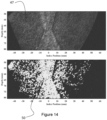
- the controller can be supported in its task by removing areas of high amplitude by setting an area of interest by cropping the data to focus solely on the full-skip region of the PAUT scan.
- the cropping applied in top part of Figure 14 is taken 5 mm from either surface of the weld to ensure that signals from the sample's surface are removed completely.
- the resultant binary image is shown in the bottom part of Figure 14 , although some indications of the parent material remains, the pixel density associated with weld matter is much higher.
- the CCF is a signal processing and image processing technique for comparing the similarity between two data series.
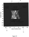
- a weld mask is overlayed over a morphological weld image.
- the weld mask is a binary image representing the ideal location of the weld to achieve full coverage of the weld.
- the mask is parsed along the index axis of the morphological image and the correlation between the two stored at every step. The point of maximum correlation can provide an estimation of the weld position and its offset to the ideal measurement location.
- the controller may be configured to compare the morphological images to a weld mask including an ideal weld position relative to the phased array ultrasonic probe; and control the actuator to move the phased array ultrasonic probe to reduce a displacement between a position of the phased array ultrasonic probe and an ideal position of the phased array ultrasonic probe based on the comparison.
- the controller may be configured to determine a similarity between the morphological images and the weld mask as a function of displacement between a weld in the morphological image and the weld in the weld mask. For instance, the controller may be configured to calculate a cross-correlation function between the morphological images and the weld mask. For instance, the controller may be configured to parse the weld mask along the morphological images in a direction perpendicular to the weld and to calculate the cross-correlation function at each increment of the morphological images that are parsed.
- the controller may be configured to determine a position of maximum cross-correlation in the morphological images and to measure a distance between the position of maximum cross-correlation and the ideal weld position.
- the physical location of the weld can be estimated using the Cross-Correlation Function (CCF).
- the CCF is a signal processing and image processing technique for comparing the similarity between two data series.
- a weld mask 52 is overlayed over a morphological weld image 50.
- the weld mask is a binary image representing the ideal location of the weld to achieve full coverage of the weld.
- the mask is parsed along the index axis of the morphological image and the correlation between the two stored at every step.
- the point of maximum correlation at the actual weld centerline 54) can provide an estimation of the weld position and its offset to the ideal measurement location 56.
- the present invention provides a novel weld localization algorithm is detailed for the automated acquisition of PAUT data of large industrial structures with remote inspection solutions.
- the present invention improves the current standard of remote crawler systems in terms of their accuracy, robustness, self-awareness, and range of inspection applications.
- the positional accuracy of remote systems for NDT is important to ensure that data is collected in accordance with on-site procedures to minimize the chance of missing defects, a task which is made harder when operating at greater lengths.
- the proposed algorithm is intended to support a remote crawler's vehicle positioning system by providing fine measurements regarding the location of the inspection site.
- the steps to deployment are also reduced as the decision making is defined by a set of human-generated rules which are not marred by legislation.
- the system relies on a difference in microstructure between parent material and weld material which is created during the welding process.
- the solidification of liquid metal causes the growth of new small grains with many boundaries.
- a series of morphological operations allow for the estimation of weld location with a mean positional error of 0.8 mm.
- the system is developed for the application of structures relate to maritime manufacturing but the method could be applied in a number of industries such as nuclear, oil & gas, renewables, aerospace etc.
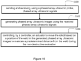
- the foregoing methods of performing NDE of a weld of a component using the robot 10 may be summarised as including the following steps: sending and receiving S100, using a phased array ultrasonic probe, phased array ultrasonic signals; generating S102 phased array ultrasonic images using the received phased array ultrasonic signals; controlling S104, by a controller, an actuator to move the robot based on a position of the weld in the generated phased array ultrasonic images to maintain a predetermined distance from the weld during the non-destructive evaluation.
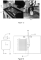
- the invention may be extended to cover a system such as shown in Figure 17 .
- Features of the system 100 that are common with the features of the robot have reference signs prefixed with a 1. Any features not described below in relation to the system are taken to have the same or equivalent function as the like features of the robot.
- a phased array ultrasonic sensing system 100 comprises a phased array ultrasonic probe 122 for sending and receiving phased array ultrasonic signals, a processor 118 configured to generate phased array ultrasonic images using the received phased array ultrasonic signals, a display 111 for displaying direction indications to guide a user in moving the phased array ultrasonic probe during a non-destructive evaluation of a weld 128 of a component 112, and a controller 116 configured to control the display to display the direction indications to guide the user in moving the phased array ultrasonic probe based on a position of the weld in the generated phased array ultrasonic images.
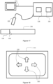
- the direction indications include a plurality of arrows 125 indicating a direction to move the phased array ultrasonic probe 122.
- the direction arrows 125 may include an up arrow, a right arrow a down arrow, and a left arrow.
- the arrow indicates that the probe 122 needs to move in that direction to become ideally placed relative to the weld 128.
- the probe 122 should not be moved in that direction.
- the probe is at an ideal location for performing a complete scan of the weld 128, no arrows are illuminated.
- the arrows may be distinguished in other ways than by brightness, e.g. they may be coloured differently, using colours explained with reference to Figure 19 below, for example.
- the direction indications include a plurality of coloured lights 127.
- the light colours may be different, e.g. red, amber, and green, to indicate relative placement of the probe 122 to the weld 128.
- the red light may indicate that the probe 122 is too far from the weld 128 to scan the weld 128.
- the green light may indicate that the probe 122 is in a correct position for scanning the weld 128.
- the amber light may mean that the probe 122 is able to partially scan the weld 128 but is not ideally located for a complete scan of the weld.
- a method of performing NDE of a weld of a component using a phased array ultrasonic probe 122 is summarised as including the following steps: sending and receiving S200, using a phased array ultrasonic probe, phased array ultrasonic signals; generating S202 phased array ultrasonic images using the received phased array ultrasonic signals; displaying S204, by a display, direction indications to guide a user of the phased array ultrasonic probe in moving the phase array ultrasonic probe based on a position of the weld in the generated phased array ultrasonic images.
- Terms such as 'component', 'module', 'processor' or 'unit' used herein may include, but are not limited to, a hardware device, such as circuitry in the form of discrete or integrated components, general processing units (GPUs), a Field Programmable Gate Array (FPGA) or Application Specific Integrated Circuit (ASIC), which performs certain tasks or provides the associated functionality.
- the described elements may be configured to reside on a tangible, persistent, addressable storage medium and may be configured to execute on one or more processors.
- These functional elements may in some embodiments include, by way of example, components, such as software components, object-oriented software components, class components and task components, processes, functions, attributes, procedures, subroutines, segments of program code, drivers, firmware, microcode, circuitry, data, databases, data structures, tables, arrays, and variables.
- components such as software components, object-oriented software components, class components and task components, processes, functions, attributes, procedures, subroutines, segments of program code, drivers, firmware, microcode, circuitry, data, databases, data structures, tables, arrays, and variables.
Landscapes
- Physics & Mathematics (AREA)
- Health & Medical Sciences (AREA)
- Life Sciences & Earth Sciences (AREA)
- Chemical & Material Sciences (AREA)
- Analytical Chemistry (AREA)
- Biochemistry (AREA)
- General Health & Medical Sciences (AREA)
- General Physics & Mathematics (AREA)
- Immunology (AREA)
- Pathology (AREA)
- Acoustics & Sound (AREA)
- Investigating Or Analyzing Materials By The Use Of Ultrasonic Waves (AREA)
Priority Applications (4)
| Application Number | Priority Date | Filing Date | Title |
|---|---|---|---|
| EP23275087.7A EP4474809A1 (fr) | 2023-06-07 | 2023-06-07 | Système de détection ultrasonore à réseau à commande de phase |
| PCT/GB2024/051433 WO2024252133A1 (fr) | 2023-06-07 | 2024-06-03 | Système de détection ultrasonore à réseau à commande de phase |
| EP24732354.6A EP4724803A1 (fr) | 2023-06-07 | 2024-06-03 | Système de détection ultrasonore à réseau à commande de phase |
| AU2024285581A AU2024285581A1 (en) | 2023-06-07 | 2024-06-03 | Phased array ultrasonic sensing system |
Applications Claiming Priority (1)
| Application Number | Priority Date | Filing Date | Title |
|---|---|---|---|
| EP23275087.7A EP4474809A1 (fr) | 2023-06-07 | 2023-06-07 | Système de détection ultrasonore à réseau à commande de phase |
Publications (1)
| Publication Number | Publication Date |
|---|---|
| EP4474809A1 true EP4474809A1 (fr) | 2024-12-11 |
Family
ID=86732548
Family Applications (1)
| Application Number | Title | Priority Date | Filing Date |
|---|---|---|---|
| EP23275087.7A Pending EP4474809A1 (fr) | 2023-06-07 | 2023-06-07 | Système de détection ultrasonore à réseau à commande de phase |
Country Status (1)
| Country | Link |
|---|---|
| EP (1) | EP4474809A1 (fr) |
Citations (3)
| Publication number | Priority date | Publication date | Assignee | Title |
|---|---|---|---|---|
| US8365602B2 (en) * | 2009-10-09 | 2013-02-05 | Olympus Ndt, Inc. | Weld seam tracking system using phased array ultrasonic devices |
| US20150346164A1 (en) * | 2014-05-30 | 2015-12-03 | Olympus Scientific Solutions Americas Inc. | System and method of dynamic gating in non-destructive weld inspection |
| US20180259489A1 (en) * | 2017-03-13 | 2018-09-13 | General Electric Company | Phased array probe and method for testing a spot-weld |
-
2023
- 2023-06-07 EP EP23275087.7A patent/EP4474809A1/fr active Pending
Patent Citations (3)
| Publication number | Priority date | Publication date | Assignee | Title |
|---|---|---|---|---|
| US8365602B2 (en) * | 2009-10-09 | 2013-02-05 | Olympus Ndt, Inc. | Weld seam tracking system using phased array ultrasonic devices |
| US20150346164A1 (en) * | 2014-05-30 | 2015-12-03 | Olympus Scientific Solutions Americas Inc. | System and method of dynamic gating in non-destructive weld inspection |
| US20180259489A1 (en) * | 2017-03-13 | 2018-09-13 | General Electric Company | Phased array probe and method for testing a spot-weld |
Similar Documents
| Publication | Publication Date | Title |
|---|---|---|
| JP5604738B2 (ja) | 進展亀裂検出方法、装置およびプログラム | |
| US20030234239A1 (en) | Method and system for assessing quality of spot welds | |
| JP2006519369A (ja) | 腐食と表面欠陥を走査するための方法と装置 | |
| EP2737242B1 (fr) | Système et procédé de contrôle d'une conduite sous-marine | |
| US20230221286A1 (en) | Inspection device, inspection method, and inspection program | |
| WO2011068604A1 (fr) | Corrélation d'informations d'inspection et de données de conception assistée par ordinateur pour évaluation structurale | |
| CN109900804A (zh) | 一种基于超声导波的金属材料裂纹定量监测方法 | |
| CN117705877A (zh) | 一种钢结构桥箱u形肋与桥面板焊缝残余应力与疲劳裂纹无人机红外成像扫查方法 | |
| KR20120051507A (ko) | 비파괴검사용 비접촉식 영상화 장치 및 방법 | |
| JP6356579B2 (ja) | 渦電流探傷装置および渦電流探傷方法 | |
| Bulavinov et al. | Industrial application of real-time 3D imaging by sampling phased array | |
| EP4109088B1 (fr) | Évaluation automatique de la qualité des données de balayage dans les essais par ultrasons | |
| US20240161267A1 (en) | Information processing device, determination method, and storage medium | |
| EP4474809A1 (fr) | Système de détection ultrasonore à réseau à commande de phase | |
| EP4474810A1 (fr) | Robot pour l'évaluation non destructive d'une soudure | |
| AU2024285581A1 (en) | Phased array ultrasonic sensing system | |
| GB2630763A (en) | Phased array ultrasonic sensing system | |
| EP4724802A1 (fr) | Robot pour la réalisation d'une évaluation non destructive d'une soudure | |
| GB2630764A (en) | Robot for performing non-destructive evaluation of a weld | |
| de Oliveira et al. | Enhanced damage measurement in a metal specimen through the image fusion of tone-burst vibro-acoustography and pulse-echo ultrasound data | |
| Gilmour et al. | Using phased array ultrasound to localize probes during the inspection of welds | |
| Ye et al. | Weld defect inspection based on machine vision and weak magnetic technology | |
| Pham et al. | Analog Magnetic Sensor-Robotic System for Steel Structure Inspection | |
| JP7455046B2 (ja) | 水中検査装置および水中検査方法 | |
| CN121476425B (en) | Nondestructive testing data processing method based on cloud platform |
Legal Events
| Date | Code | Title | Description |
|---|---|---|---|
| PUAI | Public reference made under article 153(3) epc to a published international application that has entered the european phase |
Free format text: ORIGINAL CODE: 0009012 |
|
| STAA | Information on the status of an ep patent application or granted ep patent |
Free format text: STATUS: THE APPLICATION HAS BEEN PUBLISHED |
|
| AK | Designated contracting states |
Kind code of ref document: A1 Designated state(s): AL AT BE BG CH CY CZ DE DK EE ES FI FR GB GR HR HU IE IS IT LI LT LU LV MC ME MK MT NL NO PL PT RO RS SE SI SK SM TR |