EP4474922A1 - Anzeigemechanismus für uhrwerk, der zwei konzentrische anzeigeelemente zur anzeige von zwei verschiedenen informationen steuert - Google Patents
Anzeigemechanismus für uhrwerk, der zwei konzentrische anzeigeelemente zur anzeige von zwei verschiedenen informationen steuert Download PDFInfo
- Publication number
- EP4474922A1 EP4474922A1 EP23177839.0A EP23177839A EP4474922A1 EP 4474922 A1 EP4474922 A1 EP 4474922A1 EP 23177839 A EP23177839 A EP 23177839A EP 4474922 A1 EP4474922 A1 EP 4474922A1
- Authority
- EP
- European Patent Office
- Prior art keywords
- display
- additional
- drive
- counter
- cam
- Prior art date
- Legal status (The legal status is an assumption and is not a legal conclusion. Google has not performed a legal analysis and makes no representation as to the accuracy of the status listed.)
- Withdrawn
Links
Images


Classifications
-
- G—PHYSICS
- G04—HOROLOGY
- G04B—MECHANICALLY-DRIVEN CLOCKS OR WATCHES; MECHANICAL PARTS OF CLOCKS OR WATCHES IN GENERAL; TIME PIECES USING THE POSITION OF THE SUN, MOON OR STARS
- G04B19/00—Indicating the time by visual means
- G04B19/02—Back-gearing arrangements between gear train and hands
-
- G—PHYSICS
- G04—HOROLOGY
- G04B—MECHANICALLY-DRIVEN CLOCKS OR WATCHES; MECHANICAL PARTS OF CLOCKS OR WATCHES IN GENERAL; TIME PIECES USING THE POSITION OF THE SUN, MOON OR STARS
- G04B19/00—Indicating the time by visual means
- G04B19/06—Dials
- G04B19/08—Geometrical arrangement of the graduations
- G04B19/087—Geometrical arrangement of the graduations with several separate scales
-
- G—PHYSICS
- G04—HOROLOGY
- G04F—TIME-INTERVAL MEASURING
- G04F7/00—Apparatus for measuring unknown time intervals by non-electric means
- G04F7/04—Apparatus for measuring unknown time intervals by non-electric means using a mechanical oscillator
- G04F7/08—Watches or clocks with stop devices, e.g. chronograph
- G04F7/0823—Watches or clocks with stop devices, e.g. chronograph with couplings between the chronograph mechanism and the base movement
-
- G—PHYSICS
- G04—HOROLOGY
- G04F—TIME-INTERVAL MEASURING
- G04F7/00—Apparatus for measuring unknown time intervals by non-electric means
- G04F7/04—Apparatus for measuring unknown time intervals by non-electric means using a mechanical oscillator
- G04F7/08—Watches or clocks with stop devices, e.g. chronograph
- G04F7/0866—Special arrangements
- G04F7/0885—Modular constructions involving interchangeability with one or more chronograph modules on a single base movement
-
- G—PHYSICS
- G04—HOROLOGY
- G04B—MECHANICALLY-DRIVEN CLOCKS OR WATCHES; MECHANICAL PARTS OF CLOCKS OR WATCHES IN GENERAL; TIME PIECES USING THE POSITION OF THE SUN, MOON OR STARS
- G04B19/00—Indicating the time by visual means
- G04B19/22—Arrangements for indicating different local apparent times; Universal time pieces
- G04B19/223—Arrangements for indicating different local apparent times; Universal time pieces with rotary disc, rotary bezel, or rotary dial
Definitions
- the patent application CH 709256 A2 describes a timepiece with a retrograde display comprising a single indicator hand capable of being controlled to display, in a first display mode, a first information opposite a first indicator scale and, in a second display mode, a second information opposite a second indicator scale.
- An external pushbutton allows a user to switch from one display mode to the other.
- This document merely mentions the use of a "cam and feeler system" to control the movements of the indicator needle, without however providing any concrete clue for the corresponding construction, while the latter is far from being obvious.
- this patent describes a relatively complex construction for controlling the movements of a prismatic display member, including in particular an index intended to move linearly to display three different predefined information items in three respective display modes.
- this document provides for the implementation of a synchronization wheel set comprising a pinion connected to the display index, and the movements of which are controlled alternately by three racks carried by three respective levers arranged around the synchronization wheel set, each of which is associated with one of the predefined information items.
- Each lever is held under stress by a spiral spring and carries a feeler capable of cooperating with the periphery of a specific cam whose angular orientation is a function of the corresponding predefined information item.
- a selection gear train is provided for controlling the angular orientation of a selection wheel, arranged on the synchronization wheel set, relative to the various levers.
- the selection wheel has a shape such that it can cooperate with the levers sequentially, so that only one lever at a time can be in an active state, in which its feeler is positioned in abutment against the corresponding cam, under the effect of its spiral spring, and its rack is engaged with the pinion, to control the movements of the latter according to the angular orientation of the cam.
- the selection wheel cooperates with the other two levers to keep them in an inactive state, in which their rakes are out of range of the pinion and their feelers are out of range of the corresponding cams.
- This construction has a significant overall size, both in plan, with the central location of the synchronization wheel and the distribution of the levers and their spiral springs around it, as well as with its complex display train, and in the direction of the thickness, in particular because of the structure of the synchronization wheel and all its numerous stages, necessary to ensure its proper functioning.
- the mode of cooperation chosen between the synchronization wheel and the various levers requires great precision in the manufacture and assembly of the various components involved, without any possibility of adjustment after assembly, in particular with regard to the selection wheel. It will be noted more specifically the fact that perfect synchronization is required in the operations of meshing and uncoupling the various racks with the central pinion when changing the display mode.
- a main object of the present invention is to propose a display mechanism, making it possible to control two display members so that each of them can alternately display two different pieces of information, of a construction different from that of known display mechanisms, and which has a reasonable size and limited manufacturing and assembly complexity.
- each of the drive members comprises a feeler intended to be positioned in support against the corresponding cam in its active state, under the effect of the action of an elastic member.
- the selection member is arranged and shaped in such a way that the changes of state of the first drive member and the first additional drive member, respectively of the second drive member and the second additional drive member, are synchronized.
- Such an arrangement of the selection organ, around the mobiles of the display mechanism makes it possible to significantly reduce the total thickness of the display mechanism and to simplify its construction, in particular by limiting the number of levels in which these mobiles are distributed.
- the selection cam cooperates with each of the drive members, to move it and maintain it in its inactive state, by means of a corresponding rocker, partially elastically deformable.
- the change from the inactive state to the active state of a given drive member necessarily involves the prior change from the active state to the inactive state of the other drive member associated with the same counter wheel set, which makes it possible to eliminate any risk of conflict between the teeth likely to cooperate with this counter wheel set.
- the actuation of the mobile jumpers, at each step of the selection member makes it possible to guarantee the locking of the counter wheels during changes of display modes, during the transition phases during which none of the drive members are engaged with them, in other words when all the drive members are simultaneously in the inactive state.
- one of the cams associated with one of the counter mobiles and one of the cams associated with the other of the counter mobiles together define a pair of coaxial cams.
- coaxial display mobiles it can also be provided that the pair of coaxial cams is coaxial with them.
- the selection organ carries indications intended to be visible from the outside of a timepiece housing the watch movement, to indicate at any time, to a user, on the basis of which information the counter mobiles are driven, among the predefined information.
- the present invention also relates to a watch movement comprising a display mechanism according to the preceding characteristics.
- the watch movement according to the invention comprises at least two drive mobiles arranged to drive the first and second cams and first and second additional cams, in such a way that at least two of them can be driven in rotation with different angular speeds.
- the present invention also relates to a timepiece comprising a watch movement according to the preceding characteristics.
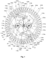
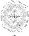
- THE figures 1 , 2 And 3 represent the same simplified view of a part of a timepiece comprising a display mechanism 2 according to a preferred embodiment of the present invention, in three different respective operating or display modes.
- timepiece Most of the elements of the timepiece are not shown for the sake of simplification and to the extent that they do not play a particular role in the implementation of the present invention. Furthermore, the timepiece is deliberately presented here in a basic form for the same sake of simplification, and the person skilled in the art will not encounter any particular difficulty in adapting the present teaching according to his own needs, and in producing a timepiece whose elements not directly related to the implementation of the invention may differ from those presented here, without departing from the scope of the invention as defined by the appended claims.
- the display mechanism 2 is shown here in the form of a display module superimposed on a watch movement or base caliber (not visible), but it could also be integrated directly into the watch movement, as an alternative, without departing from the scope of the present invention as defined by the attached set of claims.
- the display mechanism 2 comprises first and second display mobiles 4, 6, coaxial here and arranged at the center of the watch movement by way of non-limiting illustration.
- Each of the display mobiles 4, 6 is intended to carry a display member 8, 10 taking the form of an indicator hand here by way of non-limiting illustration.
- the display members 8, 10 can be driven from the watch movement, via the display mechanism 2, to indicate respectively the current hours and the current minutes.
- each of the display mobiles 4, 6 comprises a toothing, making it possible to ensure its drive, and a barrel, making it possible to make a display member integral therewith.
- Each of the display mobiles 4, 6 is connected to a counter mobile 100, 200 via a return 16, 18.
- each of the counter mobiles 100, 200 comprises a wheel meshing with the corresponding return 16, 18, and a pinion for driving the counter mobile, in a manner which will be explained later.
- the display mechanism 2 is arranged so as to be able to drive each of the display members so that it can display two different predefined information items, in two respective operating or display modes.
- the display mechanism 2 will not encounter any particular difficulty in adapting the present teaching according to their own needs, in particular to provide at least a third operating mode for at least one of the display members, in which it can occupy a different predefined angular position, without departing from the scope of the invention as defined by the appended claims.
- each of the counter mobiles 100, 200 is associated with two assemblies each comprising a cam 102a, 102b, 202a, 202b and a lever 104a, 104b, 204a, 204b, the latter playing the role of a drive member for the counter mobile 100, 200 with which it is associated, as will emerge from the remainder of the description.
- Each lever is rotatably mounted on a frame element of the display mechanism 2 or of the watch movement, for example an additional plate when the display mechanism 2 takes the form of an additional module or the main plate of the watch movement when the display mechanism 2 is integrated.
- each lever comprises two actuating surfaces 106a, 108a, 106b, 108b, 206a, 208a, 206b, 208b, intended to receive suitable forces making it possible to place the lever in an active state or in an inactive state, as will be detailed later, and located here close to its axis of rotation.
- Each lever also has an arm, extending from its axis of rotation, at the end of which are arranged a rake 110a, 110b, 210a, 210b and a feeler 112a, 112b, 212a, 212b, separated from each other by a cutout 114a, 114b, 214a, 214b.
- a rake 110a, 110b, 210a, 210b and a feeler 112a, 112b, 212a, 212b separated from each other by a cutout 114a, 114b, 214a, 214b.
- Each lever is associated with a rocker 116a, 116b, 216a, 216b comprising here a rigid portion, provided with a beak 118a, 118b, 218a, 218b, and a slightly elastic portion, arranged on either side of its axis of rotation, the elastic portion carrying an actuating finger 120a, 120b, 220a, 220b intended to cooperate with one of the actuating surfaces 106a, 106b, 206a, 206b of the corresponding lever 104a, 104b, 204a, 204b.
- a spring or elastic member 122a, 122b, 222a, 222b is associated with each of the levers 104a, 104b, 204a, 204b, such that it is capable of exerting pressure on the other of its actuating surfaces 108a, 108b, 208a, 208b.
- the display mechanism 2 comprises a selection member 20 having the shape of a rotating crown arranged outside or around a volume containing the counter mobiles 100, 200, the levers 104a, 104b, 204a, 204b, and the cams 102a, 102b, 202a, 202b, more precisely here, at the periphery of the display mechanism 2, or even of the watch movement, by way of non-limiting illustration.
- the rotating crown comprises an internal surface defining a selection cam 22 arranged to be able to cooperate with each of the levers 104a, 104b, 204a, 204b, by means of the rocker 116a, 116b, 216a, 216b associated with it, to be able to control its changes of state.
- the selection cam 22 has a plurality of inactive portions 24, located on a first radius and associated with an inactive state of the levers 104a, 104b, 204a, 204b, and a plurality of active portions 26, located on a second radius greater than the first radius, being produced in the form of notches provided in the selection member 20, and associated with an active state of the levers 104a, 104b, 204a, 204b.
- the rockers 116a, 116b, 216a, 216b are thus intended to pivot between two extreme angular orientations by passing from an inactive portion 24 to an active portion 26 of the selection cam 22, and vice versa.
- the distribution of the inactive portions 24 and the active portions 26 along the inner surface of the rotating crown, i.e. of the selection cam 22, as well as the location of the rockers 116a, 116b, 216a, 216b, are such that only one at a time among the levers 104a, 104b, 204a, 204b associated with a given counter mobile 100 or 200 can be in its active state.
- only one of the levers 104a, 104b associated with the counter 100 can be active at a time
- only one of the levers 204a, 204b associated with the counter 200 can be active at a time.
- the figure 1 represents the display mechanism 2 according to a preferred embodiment, in a first operating or display mode in which the display members 8, 10 are controlled to display the current time.
- the beaks 118b, 218b of the rockers 116b, 216b are positioned in abutment against inactive portions 24 of the selection cam 22, while the beaks 118a, 218a of the rockers 116a, 216a are positioned in abutment against active portions 26 of the selection cam 22.
- feelers 112a, 212a of the levers 104a, 204a are held in abutment against the periphery of the corresponding cams 102a, 202a, under the effect of the action of the springs 122a, 222a associated with them, while their racks 110a, 210a are engaged with the pinions of the counter mobiles 100, 200.
- the cams 102a, 202a are driven in rotation by adapted drive mobiles of the watch movement in such a way that their respective angular orientations are respectively representative of the current hours and current minutes. Consequently, the respective angular orientations of the levers 104a, 204a are also respectively function of the current hours and current minutes, and provide suitable training of the display members 8, 10 to display the current time, here 9:12.
- the levers 104a, 204a are driven according to periodic retrograde movements, the period of which corresponds to the drive period of the corresponding cam 102a, 202a, i.e. preferably here twelve hours for the cam 102a and one hour for the cam 202a.
- the display members 8, 10 are driven according to retrograde movements of the same periods, and the gear ratios between the counter mobiles 100, 200 and the display mobiles 4, 6 may be adapted according to the desired scanning angular range for each of the display members 8, 10, for example between 120 and 360 degrees.
- a jumper 28 has been shown, as a non-limiting illustrative example, being arranged to cooperate with an external toothing 30 of the selection member 20, and ensure the maintenance of the angular orientation of the latter, in a given display mode.
- the external toothing 30 defines the rhythm of the movements of the selection member 20 in response to adapted actions of a user.
- an external control body (not shown in the figure 1 ) is preferably associated with the selection member 20 to allow a user to advance it step by step, overcoming the action of the jumper 28 at each step.
- an external control body (not shown in the figure 1 ) is preferably associated with the selection member 20 to allow a user to advance it step by step, overcoming the action of the jumper 28 at each step.
- FIG. 2 which represents a simplified partial front view of the display mechanism 2, in a second operating or display mode, it can be seen that the state of each of the levers 104a, 104b, 204a, 204b of the display mechanism 2 is reversed with respect to the configuration of the figure 1 .
- the selection member 20 has undergone a rotation, in response to an adapted action of a user, to pass from the configuration of the figure 1 to that of the figure 2 , such that the beaks 118b, 218b of the rockers 116b, 216b are now positioned in abutment against active portions 26 of the selection cam 22, while the beaks 118a, 218a of the rockers 116a, 216a are positioned in abutment against inactive portions 24 of the selection cam 22.
- the feelers 112b, 212b of the levers 104b, 204b are held in abutment against the periphery of the corresponding cams 102b, 202b, under the effect of the action of the springs 122b, 222b associated with them, while their racks 110b, 210b are engaged with the pinions of the counter mobiles 100, 200.
- the cams 102b, 202b are driven in rotation by adapted drive mobiles of the watch movement, such that their respective angular orientations are respectively representative of the hours and minutes of a measured time, by way of non-limiting illustration.
- the respective angular orientations of the levers 104b, 204b are also a function respectively of the hours and minutes of a measured time, and ensure suitable driving of the display members 8, 10 to display the value of a measured time, here thirty-seven hours and twenty-six minutes (with driving of the display member 8 such that it makes a complete revolution in sixty hours, the display member 10 making a complete revolution in sixty minutes, as in the first mode of displaying the current time).
- the levers 104b, 204b are driven in retrograde movements, periodic here (but this is not necessarily the case depending on the quantities to be displayed), the period of which corresponds to the drive period of the corresponding cam 102b, 202b, i.e. preferably here sixty hours for the cam 102b and one hour for the cam 202b.
- the display members 8, 10 are therefore also driven following retrograde movements of the same respective periods as the cams 102b and 202b.
- a safety mechanism is provided as an optional preferred embodiment variant, making it possible to avoid any imperfect synchronization without requiring the extreme level of precision mentioned above, achievable but demanding.
- the pawl 32 is in the form of a rocker, a first end 34 of which fulfills the role of a jumper for the external toothing 30 of the selection member 20, while the other end 36 fulfills the role of an actuator, adapted to act on the external toothing 30 and rotate the selection member 20 by one step in the clockwise rotation direction (in the view of the Figures 1 to 3 , without limitation) in response to an adapted action by a user.
- Such an action therefore makes it possible to switch from the configuration illustrated on the figure 1 to that illustrated on the figure 3 , then another identical action allows you to switch from the configuration illustrated on the figure 3 to that illustrated on the figure 2 .
- the display mechanism 2 here advantageously comprises a movable jumper 40 associated with each of the counter mobiles 100, 200.
- Each movable jumper 40 is carried by a lever 42 rotatably mounted on a frame element of the display mechanism 2 or of the associated watch movement.
- Each lever 42 has a beak 44 held in abutment against a locking cam 46 secured to the selection member 20, under the effect of the action of an integrated spring 48, in order to be able to place the corresponding movable jumper 40 either in a rest state or in a locked state.
- the beak 44 of a given lever 42 is positioned in a hollow of the locking cam 46, the corresponding movable jumper 40 is in its rest state.
- each movable jumper 40 cooperates with a lock 50 of the corresponding counter wheel 100, 200.
- Each lock 50 is in the form of a board, integral with the wheel and the pinion of the corresponding counter wheel and, in which is formed a recess, in the shape of a V, in which the movable jumper 40 can be inserted to lock the rotation of the counter wheel, as is more particularly apparent from the view of the figure 3 .
- a third intermediate operating mode is obtained, between the two operating modes described above, and which is more of a locked or frozen mode. than a display mode as such, even though a predefined position could be provided for the display members 8, 10, in this third operating mode, which would make it possible to display a predefined fixed quantity possibly chosen by the user.
- the components of the safety mechanism are advantageously located, depending on the thickness of the display mechanism 2, at a level different from the main level containing the components enabling the display to be ensured in the first and second display modes, in order to avoid any collision during changes of operating mode.
- the locking cam 46 is adjacent to the selection cam 22, but is shaped in such a way that with each rotation of the selection member 20 by one step, the movable jumpers 40 change state, whereas the selection cam 22 is a four-stroke cam.
- the selection member 20 must rotate by four steps for the entire display mechanism 2 to perform a complete cycle, that is to say so that, starting from a given initial operating mode, it is commanded to change configuration several times until returning to the initial operating mode.
- the transition from one of the first and second display modes to the third operating mode systematically causes the transition of only the lever 104a, 104b, 204a, 204b which was active in its inactive state, so that the corresponding mobile jumper 40 can interact freely with the associated lock 50.
- the pinion is rotated at an angle slightly greater than the maximum drive angle currently being displayed (when the position of the lever 104a, 104b, 204a, 204b concerned is dictated by the angular orientation of the cam 102a, 102b, 202a, 202b with which it is associated), and the corresponding lock 50 is also rotated to an orientation suitable for being able to cooperate with the corresponding movable jumper 40, the latter effectively moving substantially simultaneously.
- V-shapes of the movable jumper 40 and the latch 50 make it possible to provide a certain tolerance in their alignments when they come into contact with each other or, conversely, when the movable jumper 40 disengages from the latch 50, during the transition from the third operating mode to one of the first two operating modes.
- the safety mechanism makes it possible to ensure correct indexing of the counter mobiles 100, 200 with the levers 104a, 104b, 204a, 204b, i.e. correct positioning of the display members 8, 10 opposite any graduations, at all times, including in the event of an impact which would occur just at the moment of a change of operating mode.
- indications 52 have been shown on the selection member 20, which can advantageously be visible on the corresponding timepiece, possibly through a suitable window, arranged in a dial.
- the indications 52 here comprise alternating “C”s and “H”s, the "C” being intended to appear through the window, where appropriate, when the operating mode corresponding to the chronograph mode is active, while the "H” is intended to be visible when the operating mode corresponding to the current time display mode is active. It can be seen on the figure 3 that the selection member 20 is oriented to cause a gap to appear between two consecutive indications 52 in the third operating mode.
- a third type of indication 52 may be provided for the third mode of operation, such as an "F” for "Frozen” or even a specific symbol.
- the general principle of the display mechanism 2 according to the present invention opens up countless possibilities in terms of quantities which can be displayed, while maintaining great simplicity and excellent readability of the corresponding display.
- FIGS. 4a, 4b and 4c represent simplified, similar front views of three different embodiments of displays which can be implemented using the general principle of the display mechanism according to the invention, by way of non-limiting illustration.
- Each of the Figures 4a, 4b and 4c represents the corresponding display in two respective different display modes.
- the Figure 4a illustrates an implementation of the display mechanism according to which the latter is arranged to be able to display the current time in a first display mode "T" on the left view, or the date in a second display mode “D” on the right view, with the hour display member 8 driven to display the current month, in relation to the hour indexes, and the minute display member 10 driven to display the date, in relation to the graduations from 1 to 31 of the standard timer.
- FIG. 4b illustrates an implementation of the display mechanism according to which the latter is arranged to be able to display the current time in a first display mode "T" on the left view, or the time in a second time zone, in a second display mode "DF" on the right view, with the hour display member 8 driven to display the time in the second time zone on a 24-hour clock, and the minute display member 10 driven in a conventional manner.
- FIG 4c illustrates a particular example of a display controlled by the display mechanism 2 which has been described in connection with the Figures 1 to 3 , the latter being arranged to be able to display the current time in a first display mode "T" on the left view, or a measured time in a second display mode "C” on the right view, with the hour display member 8 driven to display the time on 60 hours in the second mode, and the minute display member 10 driven in a conventional manner.
- An additional hand 54 for displaying the seconds of a measured time has also been illustrated here, its drive being able to be ensured in a conventional manner.
- a display mechanism is obtained, of conventional appearance and offering excellent readability, while allowing the display on demand of additional information, this mechanism being furthermore capable of being easily combined with an existing display mechanism or with an existing basic watch caliber.
- the display mechanism according to the invention allows the production of a display with multiple display modes comprising two display members arranged concentrically, while having a relatively limited bulk, in particular a reduced thickness, thanks to the particular characteristics of its selection member which allows to act in a precise, reliable and, preferably, simultaneous manner on the components controlling the two display members.
- its optional securing mechanism thanks to its optional securing mechanism, its assembly and its development can be greatly simplified in reference to prior devices.
- such a security mechanism also opens the way, more generally, to the implementation of display mechanisms which would comprise a single display member capable of being driven according to at least two different display modes, and in which the display member could be carried directly by the corresponding counter mobile, with totally reliable operation since the transition from one display mode to another would be systematically carried out by means of a fixed mode, as described above, ensuring the indexing of the pinion of the counter wheel when it is not driven.
- Such a counter wheel could then advantageously be arranged at the center of the corresponding watch movement.
- the invention is not limited by the number of display modes available, nor by the nature of the information displayed by the display members, neither in one display mode nor in another. It could also be provided that the two display members are superimposed to display a single and same quantity in one or the other of the display modes without departing from the scope of the invention as defined by the appended claims.
Landscapes
- Physics & Mathematics (AREA)
- General Physics & Mathematics (AREA)
- Geometry (AREA)
- Electromechanical Clocks (AREA)
Priority Applications (3)
| Application Number | Priority Date | Filing Date | Title |
|---|---|---|---|
| EP23177839.0A EP4474922A1 (de) | 2023-06-06 | 2023-06-06 | Anzeigemechanismus für uhrwerk, der zwei konzentrische anzeigeelemente zur anzeige von zwei verschiedenen informationen steuert |
| EP24729806.0A EP4724865A1 (de) | 2023-06-06 | 2024-05-27 | Anzeigemechanismus für uhrwerk, der zwei konzentrische anzeigeelemente zur anzeige von zwei verschiedenen informationen ermöglicht |
| PCT/EP2024/064485 WO2024251550A1 (fr) | 2023-06-06 | 2024-05-27 | Mecanisme d'affichage, pour mouvement horloger, permettant de commander deux organes d'affichage concentriques pour afficher deux informations differentes |
Applications Claiming Priority (1)
| Application Number | Priority Date | Filing Date | Title |
|---|---|---|---|
| EP23177839.0A EP4474922A1 (de) | 2023-06-06 | 2023-06-06 | Anzeigemechanismus für uhrwerk, der zwei konzentrische anzeigeelemente zur anzeige von zwei verschiedenen informationen steuert |
Publications (1)
| Publication Number | Publication Date |
|---|---|
| EP4474922A1 true EP4474922A1 (de) | 2024-12-11 |
Family
ID=86732161
Family Applications (2)
| Application Number | Title | Priority Date | Filing Date |
|---|---|---|---|
| EP23177839.0A Withdrawn EP4474922A1 (de) | 2023-06-06 | 2023-06-06 | Anzeigemechanismus für uhrwerk, der zwei konzentrische anzeigeelemente zur anzeige von zwei verschiedenen informationen steuert |
| EP24729806.0A Pending EP4724865A1 (de) | 2023-06-06 | 2024-05-27 | Anzeigemechanismus für uhrwerk, der zwei konzentrische anzeigeelemente zur anzeige von zwei verschiedenen informationen ermöglicht |
Family Applications After (1)
| Application Number | Title | Priority Date | Filing Date |
|---|---|---|---|
| EP24729806.0A Pending EP4724865A1 (de) | 2023-06-06 | 2024-05-27 | Anzeigemechanismus für uhrwerk, der zwei konzentrische anzeigeelemente zur anzeige von zwei verschiedenen informationen ermöglicht |
Country Status (2)
| Country | Link |
|---|---|
| EP (2) | EP4474922A1 (de) |
| WO (1) | WO2024251550A1 (de) |
Citations (6)
| Publication number | Priority date | Publication date | Assignee | Title |
|---|---|---|---|---|
| CH706208A2 (fr) * | 2012-03-07 | 2013-09-13 | Louis Vuitton Malletier Sa | Mouvement de montre bracelet avec un mécanisme de compensation de couple. |
| CH709256A2 (fr) | 2014-02-12 | 2015-08-14 | Manuf La Joux Perret Sa | Pièce d'horlogerie à affichage rétrograde. |
| EP2933692A1 (de) * | 2014-04-16 | 2015-10-21 | Yno Sarl | Anzeigevorrichtung |
| CH709913A2 (fr) * | 2014-07-22 | 2016-01-29 | Le Cercle Des Horlogers Sa | Dispositif d'affichage. |
| CH709538B1 (fr) | 2014-04-16 | 2018-05-31 | Hublot Sa | Pièce d'horlogerie. |
| WO2021171233A1 (fr) * | 2020-02-27 | 2021-09-02 | Ludovic Ballouard | Piece d'horlogerie |
-
2023
- 2023-06-06 EP EP23177839.0A patent/EP4474922A1/de not_active Withdrawn
-
2024
- 2024-05-27 EP EP24729806.0A patent/EP4724865A1/de active Pending
- 2024-05-27 WO PCT/EP2024/064485 patent/WO2024251550A1/fr not_active Ceased
Patent Citations (6)
| Publication number | Priority date | Publication date | Assignee | Title |
|---|---|---|---|---|
| CH706208A2 (fr) * | 2012-03-07 | 2013-09-13 | Louis Vuitton Malletier Sa | Mouvement de montre bracelet avec un mécanisme de compensation de couple. |
| CH709256A2 (fr) | 2014-02-12 | 2015-08-14 | Manuf La Joux Perret Sa | Pièce d'horlogerie à affichage rétrograde. |
| EP2933692A1 (de) * | 2014-04-16 | 2015-10-21 | Yno Sarl | Anzeigevorrichtung |
| CH709538B1 (fr) | 2014-04-16 | 2018-05-31 | Hublot Sa | Pièce d'horlogerie. |
| CH709913A2 (fr) * | 2014-07-22 | 2016-01-29 | Le Cercle Des Horlogers Sa | Dispositif d'affichage. |
| WO2021171233A1 (fr) * | 2020-02-27 | 2021-09-02 | Ludovic Ballouard | Piece d'horlogerie |
Also Published As
| Publication number | Publication date |
|---|---|
| WO2024251550A1 (fr) | 2024-12-12 |
| EP4724865A1 (de) | 2026-04-15 |
Similar Documents
| Publication | Publication Date | Title |
|---|---|---|
| EP2362277B1 (de) | Zeitzone auf Wunsch auf den Hauptzeigern einer Uhr | |
| EP1546818A2 (de) | Mechanische vorrichtung zur anzeige von stunden und minuten | |
| EP3602202B1 (de) | Vorrichtung zur einstellung von funktionen einer uhr | |
| EP3021175A1 (de) | Rattrapantenmechanismus mit planetengetriebe für uhren | |
| EP3882718B1 (de) | Korrekturvorrichtung mindestens einer komplikation einer uhr | |
| EP3629102A1 (de) | Anzeigemechanismus mit einer fensteranzeige | |
| EP3112956B1 (de) | Retrograder chronographenmechanismus mit einholzeiger | |
| EP3564760B1 (de) | Uhranzeigesystem | |
| EP4474922A1 (de) | Anzeigemechanismus für uhrwerk, der zwei konzentrische anzeigeelemente zur anzeige von zwei verschiedenen informationen steuert | |
| CH720836A2 (fr) | Mécanisme d'affichage, pour mouvement horloger, permettant de commander deux organes d'affichage pour afficher deux informations différentes | |
| EP4254079B1 (de) | Mechanismus zur anzeige der mondphasen für uhr | |
| CH712309A2 (fr) | Système d'affichage de la durée de marche d'un mouvement horloger. | |
| EP4500279B1 (de) | Uhrwerk mit einer vorrichtung zur anzeige von mindestens zwei zeitzonen | |
| CH712032B1 (fr) | Mécanisme de commande pour mouvement horloger. | |
| CH702718B1 (fr) | Fuseau horaire à la demande sur l'aiguillage principal d'une pièce d'horlogerie. | |
| EP4523049B1 (de) | Mechanismus zur anzeige der mondphasen für ein uhrwerk | |
| EP1960843B1 (de) | Uhrwerk | |
| EP4189489A1 (de) | Sympathische zeitnahmeanordnung | |
| EP3460588A1 (de) | Datumsmechanismus | |
| CH719558A2 (fr) | Mouvement d'horlogerie comportant un mécanisme d'affichage des phases de lune. | |
| EP4307052A1 (de) | Chronographenmechanismus für uhrwerk | |
| CH682201B5 (fr) | Mouvement de chronographe automatique à rattrapante. | |
| CH717702B1 (fr) | Ensemble sympathique d'horlogerie. | |
| WO2006108878A1 (fr) | Mecanisme d'affichage sautant de l’heure pour piece d’horlogerie | |
| CH715152B1 (fr) | Mécanisme d'affichage du quantième de type grande date. |
Legal Events
| Date | Code | Title | Description |
|---|---|---|---|
| PUAI | Public reference made under article 153(3) epc to a published international application that has entered the european phase |
Free format text: ORIGINAL CODE: 0009012 |
|
| STAA | Information on the status of an ep patent application or granted ep patent |
Free format text: STATUS: THE APPLICATION HAS BEEN PUBLISHED |
|
| AK | Designated contracting states |
Kind code of ref document: A1 Designated state(s): AL AT BE BG CH CY CZ DE DK EE ES FI FR GB GR HR HU IE IS IT LI LT LU LV MC ME MK MT NL NO PL PT RO RS SE SI SK SM TR |
|
| STAA | Information on the status of an ep patent application or granted ep patent |
Free format text: STATUS: THE APPLICATION IS DEEMED TO BE WITHDRAWN |
|
| 18D | Application deemed to be withdrawn |
Effective date: 20250612 |