EP4475111A1 - Display device - Google Patents
Display device Download PDFInfo
- Publication number
- EP4475111A1 EP4475111A1 EP23831675.6A EP23831675A EP4475111A1 EP 4475111 A1 EP4475111 A1 EP 4475111A1 EP 23831675 A EP23831675 A EP 23831675A EP 4475111 A1 EP4475111 A1 EP 4475111A1
- Authority
- EP
- European Patent Office
- Prior art keywords
- gear
- frame
- display panel
- display apparatus
- display
- Prior art date
- Legal status (The legal status is an assumption and is not a legal conclusion. Google has not performed a legal analysis and makes no representation as to the accuracy of the status listed.)
- Pending
Links
Images


Classifications
-
- F—MECHANICAL ENGINEERING; LIGHTING; HEATING; WEAPONS; BLASTING
- F16—ENGINEERING ELEMENTS AND UNITS; GENERAL MEASURES FOR PRODUCING AND MAINTAINING EFFECTIVE FUNCTIONING OF MACHINES OR INSTALLATIONS; THERMAL INSULATION IN GENERAL
- F16M—FRAMES, CASINGS OR BEDS OF ENGINES, MACHINES OR APPARATUS, NOT SPECIFIC TO ENGINES, MACHINES OR APPARATUS PROVIDED FOR ELSEWHERE; STANDS; SUPPORTS
- F16M11/00—Stands or trestles as supports for apparatus or articles placed thereon ; Stands for scientific apparatus such as gravitational force meters
- F16M11/02—Heads
- F16M11/04—Means for attachment of apparatus; Means allowing adjustment of the apparatus relatively to the stand
- F16M11/043—Allowing translations
- F16M11/045—Allowing translations adapted to left-right translation movement
-
- H—ELECTRICITY
- H05—ELECTRIC TECHNIQUES NOT OTHERWISE PROVIDED FOR
- H05K—PRINTED CIRCUITS; CASINGS OR CONSTRUCTIONAL DETAILS OF ELECTRIC APPARATUS; MANUFACTURE OF ASSEMBLAGES OF ELECTRICAL COMPONENTS
- H05K5/00—Casings, cabinets or drawers for electric apparatus
- H05K5/02—Details
- H05K5/0217—Mechanical details of casings
-
- F—MECHANICAL ENGINEERING; LIGHTING; HEATING; WEAPONS; BLASTING
- F16—ENGINEERING ELEMENTS AND UNITS; GENERAL MEASURES FOR PRODUCING AND MAINTAINING EFFECTIVE FUNCTIONING OF MACHINES OR INSTALLATIONS; THERMAL INSULATION IN GENERAL
- F16B—DEVICES FOR FASTENING OR SECURING CONSTRUCTIONAL ELEMENTS OR MACHINE PARTS TOGETHER, e.g. NAILS, BOLTS, CIRCLIPS, CLAMPS, CLIPS OR WEDGES; JOINTS OR JOINTING
- F16B35/00—Screw-bolts; Stay-bolts; Screw-threaded studs; Screws; Set screws
-
- F—MECHANICAL ENGINEERING; LIGHTING; HEATING; WEAPONS; BLASTING
- F16—ENGINEERING ELEMENTS AND UNITS; GENERAL MEASURES FOR PRODUCING AND MAINTAINING EFFECTIVE FUNCTIONING OF MACHINES OR INSTALLATIONS; THERMAL INSULATION IN GENERAL
- F16H—GEARING
- F16H1/00—Toothed gearings for conveying rotary motion
- F16H1/02—Toothed gearings for conveying rotary motion without gears having orbital motion
- F16H1/20—Toothed gearings for conveying rotary motion without gears having orbital motion involving more than two intermeshing members
-
- F—MECHANICAL ENGINEERING; LIGHTING; HEATING; WEAPONS; BLASTING
- F16—ENGINEERING ELEMENTS AND UNITS; GENERAL MEASURES FOR PRODUCING AND MAINTAINING EFFECTIVE FUNCTIONING OF MACHINES OR INSTALLATIONS; THERMAL INSULATION IN GENERAL
- F16M—FRAMES, CASINGS OR BEDS OF ENGINES, MACHINES OR APPARATUS, NOT SPECIFIC TO ENGINES, MACHINES OR APPARATUS PROVIDED FOR ELSEWHERE; STANDS; SUPPORTS
- F16M11/00—Stands or trestles as supports for apparatus or articles placed thereon ; Stands for scientific apparatus such as gravitational force meters
- F16M11/02—Heads
- F16M11/04—Means for attachment of apparatus; Means allowing adjustment of the apparatus relatively to the stand
- F16M11/043—Allowing translations
- F16M11/048—Allowing translations adapted to forward-backward translation movement
-
- F—MECHANICAL ENGINEERING; LIGHTING; HEATING; WEAPONS; BLASTING
- F16—ENGINEERING ELEMENTS AND UNITS; GENERAL MEASURES FOR PRODUCING AND MAINTAINING EFFECTIVE FUNCTIONING OF MACHINES OR INSTALLATIONS; THERMAL INSULATION IN GENERAL
- F16M—FRAMES, CASINGS OR BEDS OF ENGINES, MACHINES OR APPARATUS, NOT SPECIFIC TO ENGINES, MACHINES OR APPARATUS PROVIDED FOR ELSEWHERE; STANDS; SUPPORTS
- F16M11/00—Stands or trestles as supports for apparatus or articles placed thereon ; Stands for scientific apparatus such as gravitational force meters
- F16M11/02—Heads
- F16M11/18—Heads with mechanism for moving the apparatus relatively to the stand
-
- F—MECHANICAL ENGINEERING; LIGHTING; HEATING; WEAPONS; BLASTING
- F16—ENGINEERING ELEMENTS AND UNITS; GENERAL MEASURES FOR PRODUCING AND MAINTAINING EFFECTIVE FUNCTIONING OF MACHINES OR INSTALLATIONS; THERMAL INSULATION IN GENERAL
- F16M—FRAMES, CASINGS OR BEDS OF ENGINES, MACHINES OR APPARATUS, NOT SPECIFIC TO ENGINES, MACHINES OR APPARATUS PROVIDED FOR ELSEWHERE; STANDS; SUPPORTS
- F16M11/00—Stands or trestles as supports for apparatus or articles placed thereon ; Stands for scientific apparatus such as gravitational force meters
- F16M11/20—Undercarriages with or without wheels
- F16M11/2085—Undercarriages with or without wheels comprising means allowing sideward adjustment, i.e. left-right translation of the head relatively to the undercarriage
-
- F—MECHANICAL ENGINEERING; LIGHTING; HEATING; WEAPONS; BLASTING
- F16—ENGINEERING ELEMENTS AND UNITS; GENERAL MEASURES FOR PRODUCING AND MAINTAINING EFFECTIVE FUNCTIONING OF MACHINES OR INSTALLATIONS; THERMAL INSULATION IN GENERAL
- F16M—FRAMES, CASINGS OR BEDS OF ENGINES, MACHINES OR APPARATUS, NOT SPECIFIC TO ENGINES, MACHINES OR APPARATUS PROVIDED FOR ELSEWHERE; STANDS; SUPPORTS
- F16M11/00—Stands or trestles as supports for apparatus or articles placed thereon ; Stands for scientific apparatus such as gravitational force meters
- F16M11/20—Undercarriages with or without wheels
- F16M11/2092—Undercarriages with or without wheels comprising means allowing depth adjustment, i.e. forward-backward translation of the head relatively to the undercarriage
-
- G—PHYSICS
- G09—EDUCATION; CRYPTOGRAPHY; DISPLAY; ADVERTISING; SEALS
- G09F—DISPLAYING; ADVERTISING; SIGNS; LABELS OR NAME-PLATES; SEALS
- G09F9/00—Indicating arrangements for variable information in which the information is built-up on a support by selection or combination of individual elements
- G09F9/30—Indicating arrangements for variable information in which the information is built-up on a support by selection or combination of individual elements in which the desired character or characters are formed by combining individual elements
- G09F9/302—Indicating arrangements for variable information in which the information is built-up on a support by selection or combination of individual elements in which the desired character or characters are formed by combining individual elements characterised by the form or geometrical disposition of the individual elements
- G09F9/3026—Video wall, i.e. stackable semiconductor matrix display modules
-
- H—ELECTRICITY
- H05—ELECTRIC TECHNIQUES NOT OTHERWISE PROVIDED FOR
- H05K—PRINTED CIRCUITS; CASINGS OR CONSTRUCTIONAL DETAILS OF ELECTRIC APPARATUS; MANUFACTURE OF ASSEMBLAGES OF ELECTRICAL COMPONENTS
- H05K5/00—Casings, cabinets or drawers for electric apparatus
- H05K5/30—Side-by-side or stacked arrangements
Definitions
- the disclosure relates to a display apparatus and, more particularly to, a display apparatus of which a position of panels may be adjusted.
- a modular display apparatus has a large-sized screen by consecutively tiling a plurality of panels.
- the modular display apparatus has a problem in that image quality degradation and a sense of difference may occur due to a gap and a step between modules (i.e., panels).
- a display apparatus having multiple display panels and capable of precisely adjusting positions of the multiple display panels and a method thereof.
- a display apparatus includes: a frame; a plurality of display panels detachably mounted on the frame and including a first display panel and a second display panel; and a position adjusting unit provided in the frame and provided between the first display panel and the second display panel.
- the position adjusting unit includes: a first gear and a second gear configured to be rotatably connected to the frame, a third gear configured to mount the first display panel on a surface of the third gear by being coupled to the frame and by being interlocked with the first gear, and a fourth gear configured to mount the second display panel on a surface of the fourth gear by being coupled to the frame and by being interlocked with the second gear.
- the third gear may be coupled to the frame via a first screw and the fourth gear may be coupled to the frame via a second screw.
- Each of the first gear and the second gear may include a guide groove configured to insert a tool for rotating the first gear or the second gear.
- the third gear may be provided further to a left side of the display apparatus than the fourth gear.
- a height of the third gear may be the same as a height of the fourth gear.
- the frame may include: a base; and a rib member protruding in a front side further than the base, wherein the rib member is configured to support the position adjusting unit and to have a hollow at which rear ends of the first gear, the second gear, the third gear, and the fourth gear are provided.
- the plurality of display panels may be provided slidable in left or right directions of the frame.
- the plurality of display panels may include a hook member at an upper side, and the frame comprises a guide to support the hook member upward to be slidable in a right direction and a left direction.
- a display apparatus includes: a frame; a first display panel configured to be detachably mounted on the frame; a first gear configured to be rotatably connected to the frame; and a third gear configured to be interlocked with the first gear and to be coupled to the frame.
- the third gear is configured to mount the first display panel on a surface of the third gear and to move the first display panel in the first direction, based on a rotational force applied to the third gear.
- the display apparatus may further include: a second display panel configured to be detachably mounted on the frame; a second gear configured to be rotatably connected to the frame; and a fourth gear configured to be interlocked with the second gear and to be coupled to the frame.
- the fourth gear is configured to mount the second display panel on a surface of the fourth gear and to move the second display panel in the second direction, based on a rotational force applied to the fourth gear.
- the term “has,” “may have,” “includes” or “may include” indicates existence of a corresponding feature (e.g., a numerical value, a function, an operation, or a constituent element such as a component), but does not exclude existence of an additional feature.
- components required for the description of each embodiment of the disclosure are described and thus, the embodiment is not necessarily limited thereto. Accordingly, some components may be changed or omitted and other components may be added. In addition, components may be disposed and arranged in different independent devices.
- FIG. 1 is a perspective view of a display apparatus according to an embodiment of the disclosure
- FIG. 2 is an exploded perspective view of the display apparatus of FIG. 1
- FIG. 3 is a front view illustrating that the first and second display panels are spaced apart in left directions and right directions.
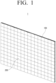
- a display apparatus 1 may include a plurality of display panels 200.
- the display apparatus 1 may display a video signal.
- the display apparatus 1 may be implemented as a television (TV), but is not limited thereto, and may be applicable to any device having a display function such as a video wall, a large format display (LFD), a digital signage, and a digital information display (DID), or the like.
- TV television
- LFD large format display
- DID digital information display
- the display apparatus 1 may be various types displays, such as a liquid crystal display (LCD), an organic light-emitting diode (OLED), a liquid crystal on silicon (LCoS), a digital light processing (DLP), a quantum dot (QD) display panel, a quantum dot light-emitting diodes (QLED), or the like.
- LCD liquid crystal display
- OLED organic light-emitting diode
- LCDoS liquid crystal on silicon
- DLP digital light processing
- QD quantum dot
- QLED quantum dot light-emitting diodes
- the display apparatus 1 may include a plurality of display panels (or a cabinet) 200.
- a plurality of display panels (or a cabinet) 200 For example, as shown in FIG. 1 , four display panels 200 may be coupled along left and right directions to implement one display apparatus 1.
- Each of the plurality of display panels 200 according to an embodiment of the disclosure may include a plurality of self-luminous elements, such as a light-emitting diode (LED) or a micro LED.
- LED light-emitting diode
- micro LED micro LED
- Each of the plurality of display panels 200 may be an LED cabinet including a plurality of LED elements.
- the LED element may be implemented as a red/green/blue (RGB) LED, which may include red LED, green LED, and blue LED.
- the LED element may additionally include a white LED, in addition to the RGB LED.
- the LED element may be a micro LED.
- the micro LED may be a LED at a size of about 5 to 100 micrometers and may be a micro-sized light-emitting element that emits light by itself without a color filter.
- the display apparatus 1 may include a frame 100, the plurality of display panels 200, and a position adjusting unit 300.
- the display apparatus 1 includes the frame 100 that supports the display panel 200.
- the display panel 200 may implement a screen of the display apparatus 1.
- the frame 100 may have an approximately rectangular shape, and may include a frame body covering the rear of the display panel 200 and a frame cover surrounding the edge portion of the frame body.
- the frame cover may form an outer appearance of an upper surface, an outer appearance of a lower surface, and an outer appearance of a side surface of the display apparatus 1.
- the display apparatus 1 may include a device board.
- the device board may include a switching mode power supply (SMPS) provided to supply power required for driving the display apparatus 1, at least one printed circuit board (PCB), and a signal processing board for processing data.
- SMPS switching mode power supply
- PCB printed circuit board
- the device board may be disposed on the frame 100, but is not limited thereto, and may be disposed on the display panel 200.
- the device board may be provided in the same number as the number of display panels 200.
- four device boards may supply power and image data to each of the four display panels 200.
- a sub-board and a cable for receiving data from each device board may be respectively arranged in the plurality of display panels 200.
- the display panel 200 may receive image data from the device board and display an image.
- the plurality of display panels 200 may be detachably mounted on a frame 100.
- the rear surface of the display panel 200 may be attached to or detached from the front surface of the frame 100 by a magnetic force.
- a plurality of first coupling members disposed on the front surface of the frame 100 and a plurality of second coupling members disposed on the rear surface (or the rear surface) of the display panel 200 may be detachably coupled to each other by attraction.
- the position adjusting unit 300 is provided in the frame 100 and may be disposed between the first display panel 210 and the second display panel 220 disposed adjacent to each other in the left and right directions among the plurality of display panels 200.
- the position adjusting unit 300 may move the first display panel 210 and the second display panel 220, and thus, arrange the panels in left and right directions or toward front or rear directions. Accordingly, steps (or gaps) between the front and rear sides of the first display panel 210 and the second display panel 220 may be adjusted.
- the first gear 310 may be disposed at a lower side of the second gear 320. In one embodiment, the first gear 310 may be disposed to be more left than the second gear 320. For example, the first gear 310 may be eccentrically disposed to the left side than the virtual vertical line, and the second gear 320 may be eccentrically disposed to the right side than the virtual vertical line.
- the third gear 330 may be disposed on the left side than the fourth gear 340.
- the third gear 330 may be disposed at a height corresponding to a height of the fourth gear 340. Accordingly, one point of the first display panel 210 in contact with the third gear 330 and one point of the second display panel 220 in contact with the fourth gear 340 may be located at the same height.
- the first gear 310 and the second gear 320 may include guide a first guide groove 311 and a second guide groove 321 into which a tool for rotating the first gear 310 and the second gear 320 may be inserted.
- the user may rotate the first gear 310 and the second gear 320 by inserting a tool into the first guide groove 311 of the first gear 310 and the second guide groove 321 of the second gear 320, instead of directly rotating the gear blades of the first gear 310 and the second gear 320. Accordingly, the user may easily rotate the first gear 310 and the second gear 320 with high force transmission efficiency.
- each of the first guide groove 311 of the first gear 310 and the second guide groove 321 of the second gear 320 may have a shape of a long groove in a vertical direction.
- the guide grooves 311, 321 may have a non-circular shape. Accordingly, a user may easily rotate the first gear 310 and the second gear 320 with high force transmission efficiency.
- the frame 100 may include a first hole H1 and a second hole H2 through which the first gear 310 and the second gear 320 pass, respectively.
- the frame 100 may also include a third hole H3 and a fourth hole H4 through which the third gear 330 and the fourth gear 340 pass, respectively. Screws engaged with the third gear 330 and the fourth gear 340 may be formed on inner circumferential surfaces of the third hole H3 and the fourth hole H4.
- the rib member 120 may be elongated along a plurality of vertical lines (L1, L2, L3).
- the rib member 120 may have a hollow 121 in which the rear ends of the first to fourth gears 310, 320, 330, 340 are arranged.
- the rib member 120 may be penetrated by the first gear 310, the second gear 320, the third gear 330, and the fourth gear 340.
- the second display panel 220 may be disposed to be stepped rearward by a step "S" as compared to the first display panel 210. Accordingly, the user may rotate the second gear 320 in one direction. Thereafter, the fourth gear 340 rotates by being engaged with the second gear 320, and is coupled to the frame 100 by a screw so that the fourth gear 340 may move forward at the same time. As shown in FIG. 7 , the second display panel 220 mounted on the front surface 341 of the fourth gear 340 may move forward to be arranged, thus the step ("S") with respect to the first display panel 210 is removed.
Landscapes
- Engineering & Computer Science (AREA)
- General Engineering & Computer Science (AREA)
- Mechanical Engineering (AREA)
- Microelectronics & Electronic Packaging (AREA)
- Multimedia (AREA)
- Physics & Mathematics (AREA)
- General Physics & Mathematics (AREA)
- Theoretical Computer Science (AREA)
- Devices For Indicating Variable Information By Combining Individual Elements (AREA)
Abstract
Description
- The disclosure relates to a display apparatus and, more particularly to, a display apparatus of which a position of panels may be adjusted.
- Demand for a display apparatus having high brightness, high resolution, enlargement, high efficiency, and low power is continuously increasing. Thus, a new product to replace or supplement a liquid crystal display (LCD) panel and an organic light-emitting diode (OLED) panel is actively studied.
- A modular display apparatus has a large-sized screen by consecutively tiling a plurality of panels.
- However, the modular display apparatus has a problem in that image quality degradation and a sense of difference may occur due to a gap and a step between modules (i.e., panels).
- Provided are a display apparatus having multiple display panels and capable of precisely adjusting positions of the multiple display panels and a method thereof.
- According to an aspect of the disclosure, a display apparatus includes: a frame; a plurality of display panels detachably mounted on the frame and including a first display panel and a second display panel; and a position adjusting unit provided in the frame and provided between the first display panel and the second display panel. The position adjusting unit includes: a first gear and a second gear configured to be rotatably connected to the frame, a third gear configured to mount the first display panel on a surface of the third gear by being coupled to the frame and by being interlocked with the first gear, and a fourth gear configured to mount the second display panel on a surface of the fourth gear by being coupled to the frame and by being interlocked with the second gear.
- The third gear may be coupled to the frame via a first screw and the fourth gear may be coupled to the frame via a second screw.
- The first display panel and the second display panel may be configured to be adjacently provided in a left side and a right side of the display apparatus, respectively.
- Each of the first gear and the second gear may include a guide groove configured to insert a tool for rotating the first gear or the second gear.
- The guide groove may have a shape of a long groove that extends in a vertical direction.
- The first gear may be provided further to a left of the display apparatus than the second gear.
- The first gear may be provided at a lower side of the second gear.
- The third gear may be provided further to a left side of the display apparatus than the fourth gear.
- A height of the third gear may be the same as a height of the fourth gear.
- The frame may include: a first hole and a second hole, wherein the first gear and the second gear respectively penetrate into the first hole and the second hole, and a third hole and a fourth hole, wherein the third gear and the fourth gear respectively penetrate into the third hole and the fourth hole.
- The frame may include: a base; and a rib member protruding in a front side further than the base, wherein the rib member is configured to support the position adjusting unit and to have a hollow at which rear ends of the first gear, the second gear, the third gear, and the fourth gear are provided.
- Additional position adjusting units may be provided and spaced apart each other along a vertical line that partitions the plurality of display panels.
- The plurality of display panels may be provided slidable in left or right directions of the frame.
- The plurality of display panels may include a hook member at an upper side, and the frame comprises a guide to support the hook member upward to be slidable in a right direction and a left direction.
- A display apparatus includes: a frame; a first display panel configured to be detachably mounted on the frame; a first gear configured to be rotatably connected to the frame; and a third gear configured to be interlocked with the first gear and to be coupled to the frame. The third gear is configured to mount the first display panel on a surface of the third gear and to move the first display panel in the first direction, based on a rotational force applied to the third gear.
- The display apparatus may further include: a second display panel configured to be detachably mounted on the frame; a second gear configured to be rotatably connected to the frame; and a fourth gear configured to be interlocked with the second gear and to be coupled to the frame. The fourth gear is configured to mount the second display panel on a surface of the fourth gear and to move the second display panel in the second direction, based on a rotational force applied to the fourth gear.
-
-
FIG. 1 illustrates a display apparatus according to an embodiment of the disclosure; -
FIG. 2 illustrates the display apparatus ofFIG. 1 ; -
FIG. 3 illustrates that the first and second display panels are spaced apart in left directions and right directions according to an embodiment of the disclosure; -
FIG. 4 illustrates a structure in which a position adjusting unit is coupled to a frame according to an embodiment of the disclosure; -
FIG. 5 illustrates a detailed structure of the position adjusting unit according to an embodiment of the disclosure; and -
FIGS. 6 and7 illustrate a process of adjusting a step of a display according to an embodiment of the disclosure. - Examples described hereinafter are for easy understanding of the disclosure, and it should be understood that various changes can be made to examples described herein and the disclosure can be embodied in different forms. In addition, in the following description, detailed descriptions of well-known functions or configurations will be omitted since they would unnecessarily obscure the subject matters of the disclosure.
- In addition, it should be noted that the drawings as attached are just for easy understanding of the disclosure, and are not illustrated as really scaled, and dimensions of some elements may be exaggerated. Embodiments of the disclosure will be described in detail with reference to the accompanying drawings, but the disclosure is not limited to embodiments described herein.
- General terms that are currently widely used were selected as terms used in embodiments of the disclosure in consideration of functions in the disclosure, but may be changed depending on the intention of those skilled in the art or a judicial precedent, the emergence of a new technique, and the like. In addition, in a specific case, terms arbitrarily chosen by an applicant may exist. In this case, the meaning of such terms will be mentioned in detail in a corresponding description portion of the disclosure. Therefore, the terms used in embodiments of the disclosure should be defined on the basis of the meaning of the terms and the contents throughout the disclosure rather than simple names of the terms.
- As used herein, the term "has," "may have," "includes" or "may include" indicates existence of a corresponding feature (e.g., a numerical value, a function, an operation, or a constituent element such as a component), but does not exclude existence of an additional feature.
- In the disclosure, components required for the description of each embodiment of the disclosure are described and thus, the embodiment is not necessarily limited thereto. Accordingly, some components may be changed or omitted and other components may be added. In addition, components may be disposed and arranged in different independent devices.
- Embodiments of the disclosure will be described in detail with reference to the accompanying drawings, but the disclosure is not limited to embodiments described herein.
- The disclosure will be described in detail with reference to the drawings.
-
FIG. 1 is a perspective view of a display apparatus according to an embodiment of the disclosure;FIG. 2 is an exploded perspective view of the display apparatus ofFIG. 1 ;FIG. 3 is a front view illustrating that the first and second display panels are spaced apart in left directions and right directions. - According to an embodiment, a
display apparatus 1 may include a plurality ofdisplay panels 200. Thedisplay apparatus 1 may display a video signal. Thedisplay apparatus 1 may be implemented as a television (TV), but is not limited thereto, and may be applicable to any device having a display function such as a video wall, a large format display (LFD), a digital signage, and a digital information display (DID), or the like. - In addition, the
display apparatus 1 may be various types displays, such as a liquid crystal display (LCD), an organic light-emitting diode (OLED), a liquid crystal on silicon (LCoS), a digital light processing (DLP), a quantum dot (QD) display panel, a quantum dot light-emitting diodes (QLED), or the like. - According to an embodiment, the
display apparatus 1 may include a plurality of display panels (or a cabinet) 200. For example, as shown inFIG. 1 , fourdisplay panels 200 may be coupled along left and right directions to implement onedisplay apparatus 1. Each of the plurality ofdisplay panels 200 according to an embodiment of the disclosure may include a plurality of self-luminous elements, such as a light-emitting diode (LED) or a micro LED. - Each of the plurality of
display panels 200 may be an LED cabinet including a plurality of LED elements. According to one embodiment, the LED element may be implemented as a red/green/blue (RGB) LED, which may include red LED, green LED, and blue LED. In addition, the LED element may additionally include a white LED, in addition to the RGB LED. The LED element may be a micro LED. Here, the micro LED may be a LED at a size of about 5 to 100 micrometers and may be a micro-sized light-emitting element that emits light by itself without a color filter. - Referring to
FIGS. 1 to 3 , thedisplay apparatus 1 according to an embodiment of the disclosure may include aframe 100, the plurality ofdisplay panels 200, and aposition adjusting unit 300. - Referring to
FIG. 1 , thedisplay apparatus 1 includes theframe 100 that supports thedisplay panel 200. Thedisplay panel 200 may implement a screen of thedisplay apparatus 1. - The
frame 100 according to an embodiment may have an approximately rectangular shape, and may include a frame body covering the rear of thedisplay panel 200 and a frame cover surrounding the edge portion of the frame body. In one embodiment, the frame cover may form an outer appearance of an upper surface, an outer appearance of a lower surface, and an outer appearance of a side surface of thedisplay apparatus 1. - According to an embodiment of the disclosure, the
display apparatus 1 may include a device board. The device board may include a switching mode power supply (SMPS) provided to supply power required for driving thedisplay apparatus 1, at least one printed circuit board (PCB), and a signal processing board for processing data. - The device board may be disposed on the
frame 100, but is not limited thereto, and may be disposed on thedisplay panel 200. The device board may be provided in the same number as the number ofdisplay panels 200. For example, four device boards may supply power and image data to each of the fourdisplay panels 200. A sub-board and a cable for receiving data from each device board may be respectively arranged in the plurality ofdisplay panels 200. Thedisplay panel 200 may receive image data from the device board and display an image. - The plurality of
display panels 200 may be detachably mounted on aframe 100. According to an embodiment, the rear surface of thedisplay panel 200 may be attached to or detached from the front surface of theframe 100 by a magnetic force. For example, a plurality of first coupling members disposed on the front surface of theframe 100 and a plurality of second coupling members disposed on the rear surface (or the rear surface) of thedisplay panel 200 may be detachably coupled to each other by attraction. - As illustrated in
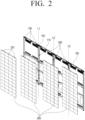
FIG. 2 , theposition adjusting unit 300 is provided in theframe 100 and may be disposed between thefirst display panel 210 and thesecond display panel 220 disposed adjacent to each other in the left and right directions among the plurality ofdisplay panels 200. Theposition adjusting unit 300 may move thefirst display panel 210 and thesecond display panel 220, and thus, arrange the panels in left and right directions or toward front or rear directions. Accordingly, steps (or gaps) between the front and rear sides of thefirst display panel 210 and thesecond display panel 220 may be adjusted. - As illustrated in
FIG. 2 , a plurality ofposition adjusting units 300 are provided to be spaced apart from each other along vertical lines (L1, L2, L3) dividing the plurality ofdisplay panels 200. Each of the vertical lines (L1, L2, L3) may be a virtual line defining a boundary in the vertical direction of thedisplay panel 200. For example, when fourdisplay panels 200 are arranged as illustrated inFIG. 2 , three vertical lines (L1, L2, L3) may be used. - The plurality of
display panels 200 may be arranged to be slidable in left and right directions in theframe 100. Accordingly, the plurality ofdisplay panels 200 may move to the left direction or the right direction while being mounted on theframe 100. - For example, a user may mount the
first display panel 210 and thesecond display panel 220 on theframe 100 to form a gap in which theposition adjusting unit 300 is exposed between thefirst display panel 210 and thesecond display panel 220. Then, the user may adjust a step (or a distance) between front and rear sides of thefirst display panel 210 and thesecond display panel 220 by using theposition adjusting unit 300. Thus, thefirst display panel 210 and thesecond display panel 220 may be slid to the left direction and to the right direction so that the gap formed between thefirst display panel 210 and thesecond display panel 220 may be removed, and theposition adjusting unit 300 may be hidden by thefirst display panel 210 and thesecond display panel 220. - As illustrated in
FIG. 2 , for example, the plurality ofdisplay panels 200 may include ahook member 201 at the upper end of thedisplay panel 200. As illustrated inFIG. 3 , theframe 100 may include aguide 130 for supporting thehook member 201 upward in the left and right directions. Accordingly, the plurality ofdisplay panels 200 may slide to the left direction or the right direction while thehook member 201 is hung on theguide 130. -
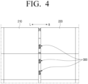
FIG. 4 is a perspective view illustrating a structure in which a position adjusting unit is coupled to a frame.FIG. 5 is a perspective view illustrating a detailed structure of the position adjusting unit; andFIGS. 6 and7 are top views illustrating a process of adjusting a step of a display. - Referring to
FIGS. 4 to 7 , theposition adjusting unit 300 may include afirst gear 310, asecond gear 320, athird gear 330, and afourth gear 340. - The
first gear 310 and thesecond gear 320 may be rotatably connected to theframe 100. In one embodiment, thefirst gear 310 and thesecond gear 320 may rotate around a rotation axis extending along the front and rear sides. - The
third gear 330 is coupled to the frame 100 (e.g., by a screw) and is engaged (e.g., interlocked) with thefirst gear 310. Thefirst display panel 210 may be mounted on afront surface 331 of thethird gear 330. - The
fourth gear 340 may be coupled to the frame 100 (e.g., by a screw) and disposed to be engaged (e.g., interlocked) with thesecond gear 320. Thesecond display panel 220 may be mounted on afront surface 341 of thefourth gear 340. - The
third gear 330 and thefourth gear 340 are coupled to the frame 100 (e.g., by a screw), so that the rotational movement and the forward/backward straight movement of the gears may be interlocked. That is, when thethird gear 330 and thefourth gear 340 rotate in one direction, thethird gear 330 and thefourth gear 340 may move forward ("F" inFIG. 5 ) along the screw. Also, thethird gear 330 and thefourth gear 340 may move backward or in a rear direction ("R" inFIG. 5 ) along the screw when thethird gear 330 and thefourth gear 340 rotate in the other direction. - When the user rotates the
first gear 310 and thesecond gear 320, thethird gear 330 and thefourth gear 340, which are engaged (e.g., interlocked) with thefirst gear 310 and thesecond gear 320, may rotate, and thethird gear 330 and thefourth gear 340 may move forward or backward at the same time. Accordingly, a step between thefirst display panel 210 and thesecond display panel 220 may be adjusted or removed. - In one embodiment, the
first gear 310 may be disposed at a lower side of thesecond gear 320. In one embodiment, thefirst gear 310 may be disposed to be more left than thesecond gear 320. For example, thefirst gear 310 may be eccentrically disposed to the left side than the virtual vertical line, and thesecond gear 320 may be eccentrically disposed to the right side than the virtual vertical line. - Accordingly, when the user rotates the
first gear 310 that is eccentric to the left, the user may move thefirst display panel 210 disposed on the left side, and when thesecond gear 320 eccentric to the right is rotated, the user may easily recognize that thesecond display panel 220 disposed on the right side may move. - The
third gear 330 may be disposed on the left side than thefourth gear 340. Thethird gear 330 may be disposed at a height corresponding to a height of thefourth gear 340. Accordingly, one point of thefirst display panel 210 in contact with thethird gear 330 and one point of thesecond display panel 220 in contact with thefourth gear 340 may be located at the same height. - That is, the adjustment of the step of first and
second display panels first display panel 210 and thesecond display panel 220 more precisely. - The
first gear 310 and thesecond gear 320 may include guide afirst guide groove 311 and asecond guide groove 321 into which a tool for rotating thefirst gear 310 and thesecond gear 320 may be inserted. The user may rotate thefirst gear 310 and thesecond gear 320 by inserting a tool into thefirst guide groove 311 of thefirst gear 310 and thesecond guide groove 321 of thesecond gear 320, instead of directly rotating the gear blades of thefirst gear 310 and thesecond gear 320. Accordingly, the user may easily rotate thefirst gear 310 and thesecond gear 320 with high force transmission efficiency. - In one embodiment, each of the
first guide groove 311 of thefirst gear 310 and thesecond guide groove 321 of thesecond gear 320 may have a shape of a long groove in a vertical direction. Theguide grooves first gear 310 and thesecond gear 320 with high force transmission efficiency. - As illustrated in
FIG. 6 , theframe 100 may include a first hole H1 and a second hole H2 through which thefirst gear 310 and thesecond gear 320 pass, respectively. Theframe 100 may also include a third hole H3 and a fourth hole H4 through which thethird gear 330 and thefourth gear 340 pass, respectively. Screws engaged with thethird gear 330 and thefourth gear 340 may be formed on inner circumferential surfaces of the third hole H3 and the fourth hole H4. - The
frame 100 may include abase 110 and arib member 120. The base 110 may be a plate arranged in parallel with thedisplay panel 200. Therib member 120 may be arranged to protrude in front of the base 110 to support theposition adjusting unit 300. - The
rib member 120 may be elongated along a plurality of vertical lines (L1, L2, L3). Therib member 120 may have a hollow 121 in which the rear ends of the first tofourth gears rib member 120 may be penetrated by thefirst gear 310, thesecond gear 320, thethird gear 330, and thefourth gear 340. - Even if the
third gear 330 and thefourth gear 340 move forward or backward, they may freely move inside the hollow 121 formed in therib member 120 without interfering with theframe 100. - Referring to
FIG. 6 , thesecond display panel 220 may be disposed to be stepped rearward by a step "S" as compared to thefirst display panel 210. Accordingly, the user may rotate thesecond gear 320 in one direction. Thereafter, thefourth gear 340 rotates by being engaged with thesecond gear 320, and is coupled to theframe 100 by a screw so that thefourth gear 340 may move forward at the same time. As shown inFIG. 7 , thesecond display panel 220 mounted on thefront surface 341 of thefourth gear 340 may move forward to be arranged, thus the step ("S") with respect to thefirst display panel 210 is removed. - The disclosure is not limited to the specific embodiments described above, but various modifications can be made by one of ordinary skill in the art to which the disclosure belongs without departing from the subject matter of the disclosure claimed in the claims, and such modifications are within the scope of the claims.
Claims (15)
- A display apparatus comprising:a frame;a plurality of display panels detachably mounted on the frame, wherein the plurality of display panels comprises a first display panel and a second display panel that are adjacent to each other; anda position adjusting unit provided in the frame and between the first display panel and the second display panel,wherein the position adjusting unit comprises:a first gear rotatably connected to the frame,a second gear rotatably connected to the frame,a third gear configured to mount the first display panel on a surface of the third gear by being coupled to the frame and by being interlocked with the first gear, anda fourth gear configured to mount the second display panel on a surface of the fourth gear by being coupled to the frame and by being interlocked with the second gear.
- The display apparatus of claim 1, wherein the third gear is coupled to the frame via a first screw and the fourth gear is coupled to the frame via a second screw.
- The display apparatus of claim 1, wherein each of the first gear and the second gear comprises a guide groove configured to receive a tool inserted therein for rotating the first gear or the second gear.
- The display apparatus of claim 3, wherein the guide groove extends in a vertical direction.
- The display apparatus of claim 1, wherein the first gear is disposed further to a left of the display apparatus than the second gear.
- The display apparatus of claim 1, wherein the first gear is disposed at a lower side of the second gear.
- The display apparatus of claim 1, wherein the third gear is provided further to a left side of the display apparatus than the fourth gear.
- The display apparatus of claim 1, wherein a height of the third gear is the same as a height of the fourth gear.
- The display apparatus of claim 1, wherein the frame comprises:a first hole and a second hole through which the first gear and the second gear penetrate respectively, anda third hole and a fourth hole through which the third gear and the fourth gear penetrate respectively.
- The display apparatus of claim 1, wherein the frame comprises:a base; anda rib member protruding in a front side further than the base, andwherein the rib member supports the position adjusting unit and has a hollow at which rear ends of the first gear, the second gear, the third gear, and the fourth gear are disposed.
- The display apparatus of claim 1, wherein additional position adjusting units are provided and spaced apart each other along a vertical line that partitions the plurality of display panels.
- The display apparatus of claim 1, wherein the plurality of display panels are slidable in left or right directions in the frame.
- The display apparatus of claim 12, wherein the plurality of display panels comprise a hook member at an upper side, and
wherein the frame comprises a guide to support the hook member upward to be slidable in a right direction and a left direction. - A display apparatus comprising:a frame;a first display panel detachably mounted on the frame;a first gear rotatably connected to the frame; anda third gear interlocked with the first gear and coupled to the frame,wherein the third gear is configured to mount the first display panel on a surface of the third gear and to move the first display panel in the first direction, based on a rotational force applied to the third gear.
- The display apparatus of claim 14, further comprising:a second display panel detachably mounted on the frame;a second gear rotatably connected to the frame; anda fourth gear configured to be interlocked with the second gear and to be coupled to the frame,wherein the fourth gear is configured to mount the second display panel on a surface of the fourth gear and to move the second display panel in the second direction, based on a rotational force applied to the fourth gear.
Applications Claiming Priority (2)
| Application Number | Priority Date | Filing Date | Title |
|---|---|---|---|
| KR1020220080026A KR20240002620A (en) | 2022-06-29 | 2022-06-29 | Display apparatus |
| PCT/KR2023/004376 WO2024005309A1 (en) | 2022-06-29 | 2023-03-31 | Display device |
Publications (2)
| Publication Number | Publication Date |
|---|---|
| EP4475111A1 true EP4475111A1 (en) | 2024-12-11 |
| EP4475111A4 EP4475111A4 (en) | 2025-05-28 |
Family
ID=89380870
Family Applications (1)
| Application Number | Title | Priority Date | Filing Date |
|---|---|---|---|
| EP23831675.6A Pending EP4475111A4 (en) | 2022-06-29 | 2023-03-31 | DISPLAY DEVICE |
Country Status (5)
| Country | Link |
|---|---|
| US (2) | US12446170B2 (en) |
| EP (1) | EP4475111A4 (en) |
| KR (1) | KR20240002620A (en) |
| CN (1) | CN119013716A (en) |
| WO (1) | WO2024005309A1 (en) |
Families Citing this family (1)
| Publication number | Priority date | Publication date | Assignee | Title |
|---|---|---|---|---|
| WO2025244158A1 (en) | 2024-05-24 | 2025-11-27 | 엘지전자 주식회사 | Display device |
Family Cites Families (12)
| Publication number | Priority date | Publication date | Assignee | Title |
|---|---|---|---|---|
| JP6378104B2 (en) | 2015-01-30 | 2018-08-22 | 株式会社フォトクラフト社 | Video display device and method for adjusting assembly thereof |
| KR102272059B1 (en) | 2015-02-09 | 2021-07-05 | 삼성전자주식회사 | Display module and display device comprising the same |
| KR101705511B1 (en) * | 2015-10-08 | 2017-03-31 | 주식회사 에이블테크 | Display device |
| US11573613B2 (en) * | 2017-05-22 | 2023-02-07 | Mitsubishi Electric Corporation | Display module group, display device, and display device production method |
| JP6425858B1 (en) | 2018-02-06 | 2018-11-21 | 三菱電機株式会社 | Multi-display system and video display device |
| KR102455299B1 (en) | 2018-03-07 | 2022-10-17 | 엘지전자 주식회사 | Display device |
| US11353732B2 (en) * | 2018-08-24 | 2022-06-07 | Samsung Electronics Co., Ltd. | Display apparatus |
| KR102489223B1 (en) * | 2018-09-28 | 2023-01-17 | 엘지디스플레이 주식회사 | Gap regulator of multi display and multi display having the same |
| CN210715418U (en) * | 2019-09-02 | 2020-06-09 | 利亚德光电股份有限公司 | Gap adjusting tool of display screen and display screen assembly |
| CN111425722A (en) * | 2020-05-07 | 2020-07-17 | 深圳市亮彩科技有限公司 | L ED four-screen automatic linkage device |
| CN115917628A (en) * | 2020-08-28 | 2023-04-04 | Lg电子株式会社 | display device |
| CN113700996B (en) * | 2021-08-24 | 2023-08-01 | 深圳市华星光电半导体显示技术有限公司 | Spliced screen gap adjusting device and adjusting method |
-
2022
- 2022-06-29 KR KR1020220080026A patent/KR20240002620A/en active Pending
-
2023
- 2023-03-31 WO PCT/KR2023/004376 patent/WO2024005309A1/en not_active Ceased
- 2023-03-31 EP EP23831675.6A patent/EP4475111A4/en active Pending
- 2023-03-31 CN CN202380036492.7A patent/CN119013716A/en active Pending
- 2023-04-26 US US18/139,472 patent/US12446170B2/en active Active
-
2025
- 2025-09-24 US US19/338,553 patent/US20260020170A1/en active Pending
Also Published As
| Publication number | Publication date |
|---|---|
| US20260020170A1 (en) | 2026-01-15 |
| US20240008198A1 (en) | 2024-01-04 |
| WO2024005309A1 (en) | 2024-01-04 |
| US12446170B2 (en) | 2025-10-14 |
| KR20240002620A (en) | 2024-01-05 |
| EP4475111A4 (en) | 2025-05-28 |
| CN119013716A (en) | 2024-11-22 |
Similar Documents
| Publication | Publication Date | Title |
|---|---|---|
| US11935440B2 (en) | Display apparatus and hinge assembly of display module | |
| US11674218B2 (en) | Lightweight unitary display | |
| CN111966309B (en) | Display device and display system having the same | |
| US20260020170A1 (en) | Display apparatus | |
| EP1722267B1 (en) | Backlight unit and liquid crystal display employing the same | |
| EP2116986A2 (en) | Support structure for a LED display system | |
| KR102590119B1 (en) | Display apparatus | |
| EP2487404A1 (en) | Light source module and electronic apparatus provided with same | |
| KR102209285B1 (en) | height adjustable type LED display apparatus | |
| KR20200023151A (en) | Display appartus | |
| EP3276978B1 (en) | Sound system and display device comprising it | |
| KR20170118318A (en) | Display device | |
| US20250071917A1 (en) | Connection bracket and display apparatus including the same | |
| KR20150125141A (en) | Variable display device and method for driving a flat mode and curved mode the same | |
| US12288488B2 (en) | Display apparatus | |
| EP4668049A1 (en) | Connection bracket and display apparatus including same | |
| CN114974051A (en) | Control method of LED display screen, LED display screen and electronic equipment | |
| KR20230090944A (en) | Display apparatus | |
| KR102452144B1 (en) | LED signage equipped with height adjustment device | |
| US20250285563A1 (en) | Display apparatus | |
| US20250318064A1 (en) | Separation device and display device comprising same | |
| KR20240028794A (en) | Display device | |
| KR20240026679A (en) | Display device | |
| KR20250028138A (en) | Connection bracket and display device having the same | |
| KR20250028913A (en) | Connection bracket and display device having the same |
Legal Events
| Date | Code | Title | Description |
|---|---|---|---|
| STAA | Information on the status of an ep patent application or granted ep patent |
Free format text: STATUS: THE INTERNATIONAL PUBLICATION HAS BEEN MADE |
|
| PUAI | Public reference made under article 153(3) epc to a published international application that has entered the european phase |
Free format text: ORIGINAL CODE: 0009012 |
|
| STAA | Information on the status of an ep patent application or granted ep patent |
Free format text: STATUS: REQUEST FOR EXAMINATION WAS MADE |
|
| 17P | Request for examination filed |
Effective date: 20240905 |
|
| AK | Designated contracting states |
Kind code of ref document: A1 Designated state(s): AL AT BE BG CH CY CZ DE DK EE ES FI FR GB GR HR HU IE IS IT LI LT LU LV MC ME MK MT NL NO PL PT RO RS SE SI SK SM TR |
|
| A4 | Supplementary search report drawn up and despatched |
Effective date: 20250429 |
|
| RIC1 | Information provided on ipc code assigned before grant |
Ipc: F16H 1/20 20060101ALI20250423BHEP Ipc: F16B 35/00 20060101ALI20250423BHEP Ipc: G09F 9/302 20060101AFI20250423BHEP |
|
| DAV | Request for validation of the european patent (deleted) | ||
| DAX | Request for extension of the european patent (deleted) |