EP4475122A1 - Anpassung räumlicher audioparameter für jitterpufferverwaltung - Google Patents
Anpassung räumlicher audioparameter für jitterpufferverwaltung Download PDFInfo
- Publication number
- EP4475122A1 EP4475122A1 EP23177532.1A EP23177532A EP4475122A1 EP 4475122 A1 EP4475122 A1 EP 4475122A1 EP 23177532 A EP23177532 A EP 23177532A EP 4475122 A1 EP4475122 A1 EP 4475122A1
- Authority
- EP
- European Patent Office
- Prior art keywords
- subframe
- audio signal
- signal frame
- time slots
- slot
- Prior art date
- Legal status (The legal status is an assumption and is not a legal conclusion. Google has not performed a legal analysis and makes no representation as to the accuracy of the status listed.)
- Pending
Links
Images





Classifications
-
- G—PHYSICS
- G10—MUSICAL INSTRUMENTS; ACOUSTICS
- G10L—SPEECH ANALYSIS TECHNIQUES OR SPEECH SYNTHESIS; SPEECH RECOGNITION; SPEECH OR VOICE PROCESSING TECHNIQUES; SPEECH OR AUDIO CODING OR DECODING
- G10L19/00—Speech or audio signals analysis-synthesis techniques for redundancy reduction, e.g. in vocoders; Coding or decoding of speech or audio signals, using source filter models or psychoacoustic analysis
- G10L19/008—Multichannel audio signal coding or decoding using interchannel correlation to reduce redundancy, e.g. joint-stereo, intensity-coding or matrixing
-
- G—PHYSICS
- G10—MUSICAL INSTRUMENTS; ACOUSTICS
- G10L—SPEECH ANALYSIS TECHNIQUES OR SPEECH SYNTHESIS; SPEECH RECOGNITION; SPEECH OR VOICE PROCESSING TECHNIQUES; SPEECH OR AUDIO CODING OR DECODING
- G10L19/00—Speech or audio signals analysis-synthesis techniques for redundancy reduction, e.g. in vocoders; Coding or decoding of speech or audio signals, using source filter models or psychoacoustic analysis
- G10L19/005—Correction of errors induced by the transmission channel, if related to the coding algorithm
Definitions
- the present application relates to apparatus and methods for adapting spatial audio metadata for the provision of jitter buffer management in immersive and spatial audio codecs.
- Parametric spatial audio capture from inputs is a typical and an effective choice to estimate from the input (microphone array signals) a set of parameters such as directions of the sound in frequency bands, and the ratios between the directional and non-directional parts of the captured sound in frequency bands. These parameters are known to well describe the perceptual spatial properties of the captured sound at the position of the microphone array. These parameters can be utilized in synthesis of the spatial sound accordingly, for headphones binaurally, for loudspeakers, or to other formats, such as Ambisonics.
- the directions and direct-to-total and diffuse-to-total energy ratios in frequency bands are thus a parameterization that is particularly effective for spatial audio capture.
- a parameter set consisting of a direction parameter in frequency bands and an energy ratio parameter in frequency bands (indicating the directionality of the sound) can be also utilized as the spatial metadata (which may also include other parameters such as surround coherence, spread coherence, number of directions, distance etc) for an audio codec.
- these parameters can be estimated from microphone-array captured audio signals, and, for example, a stereo or mono signal can be generated from the microphone array signals to be conveyed with the spatial metadata.
- Immersive audio codecs are being implemented supporting a multitude of operating points ranging from a low bit rate operation to transparency.
- An example of such a codec is the Immersive Voice and Audio Services (IVAS) codec which is being designed to be suitable for use over a communications network such as a 3GPP 4G/5G network including use in such immersive services as for example immersive voice and audio for virtual reality (VR).
- IVAS Immersive Voice and Audio Services
- This audio codec is expected to handle the encoding, decoding and rendering of speech, music and generic audio. It is furthermore expected to support channel-based audio, object-based audio, and scene-based audio inputs including spatial information about the sound field and sound sources.
- the codec is also expected to operate with low latency to enable conversational services as well as support high error robustness under various transmission conditions.
- a decoder can decode the audio signals into PCM (Pulse code modulation) signals.
- the decoder can also process the sound in frequency bands (using the spatial metadata) to obtain the spatial
- the aforementioned immersive audio codecs are particularly suitable for encoding captured spatial sound from microphone arrays (e.g., in mobile phones, VR cameras, stand-alone microphone arrays).
- microphone arrays e.g., in mobile phones, VR cameras, stand-alone microphone arrays.
- an encoder can have other input types, for example, loudspeaker signals, audio object signals, or Ambisonic signals.
- the decoder can output the audio in supported formats.
- the IVAS decoder is also expected to handle the encoded audio streams and accompanying spatial audio metadata as RTP packets which may arrive with varying degrees of delay as a result of network jitter conditions in a packet-based network.
- immersive audio codecs such as 3GPP IVAS
- immersive audio codecs are being planned which support a multitude of operating points ranging from a low bit rate operation to transparency. It is expected to support channel-based audio, object-based audio, and scene-based audio inputs including spatial information about the sound field and sound sources.
- the example codec is configured to be able to receive multiple input formats.
- the codec is configured to obtain or receive a multi audio signal (for example, received from a microphone array, or as a multichannel audio format input, or an Ambisonics format input).
- the codec is configured to handle more than one input format at a time.
- Metadata-Assisted Spatial Audio is an example of a parametric spatial audio format and representation suitable as an input format for IVAS.
- spatial metadata associated with the audio signals may comprise multiple parameters (such as multiple directions and associated with each direction (or directional value) a direct-to-total energy ratio, spread coherence, distance, etc.) per time-frequency (TF) tile.
- the spatial metadata may also comprise other parameters or may be associated with other parameters which are considered to be non-directional (such as surround coherence, diffuse-to-total energy ratio, remainder-to-total energy ratio) but when combined with the directional parameters are able to be used to define the characteristics of the audio scene.
- a reasonable design choice which is able to produce a good quality output is one where the spatial metadata comprises one or more directions for each time-frequency subframe (and associated with each direction direct-to-total ratios, spread coherence, distance values etc) are determined.
- the MASA analyser 101 is configured to receive the input audio signal(s) 100 and analyse the input audio signals to generate transport audio signal(s) 102 and spatial metadata 104.
- the transport audio signal(s) 102 can be encoded, for example, using an IVAS audio core codec, or with an AAC (Advanced Audio Coding) or EVS (Enhanced Voice Services) encoder.
- AAC Advanced Audio Coding
- EVS Enhanced Voice Services
- MASA spatial metadata is presented in the following table. These values are available for each time-frequency tile.
- a frame is subdivided into 24 frequency bands and 4 temporal sub-frames. In other implementations other divisions of frequency and time can be employed.
- a frame size (for example, as implemented in IVAS) is 20 ms (and thus the temporal sub-frame is 5 ms).
- the MASA analyser is configured to determine 1 or 2 directions for each time-frequency tile (i.e., there are 1 or 2 direction index, direct-to-total energy ratio, and spread coherence parameters for each time-frequency tile).
- the analyser is configured to generate more than 2 directions for a time-frequency tile.
- Field bits Description Direction index 16 Direction of arrival of the sound at a time-frequency parameter interval.
- Remainder-to-total energy ratio 8 Energy ratio of the remainder (such as microphone noise) sound energy to fulfil requirement that sum of energy ratios is 1. Calculated as energy of remainder sound / total energy. Range of values: [0.0, 1.0] (Parameter is independent of number of directions provided.) Values stored as 8-bit unsigned integers with uniform spacing of mapped values.
- the frame size in IVAS is 20 ms.
- An example of the frame structure is shown in Figure 2 where the metadata frame 201 comprises four temporal sub-frames which are 5 ms long, metadata sub-frame 1 202, metadata sub-frame 2 204, metadata sub-frame 3 206, and metadata sub-frame 4 208.
- the IVAS frame can also be formed as a TF-representation of a complex-valued low delay filter band (CLDFB) where each subframe comprises 4 TF-slots and in the case of the above example this equates to each slot corresponding to 1.25 ms.
- An example of the IVAS frame structure 300 corresponding to the TF-representation of the CLDFB is shown in Figure 3 .
- the MASA stream can be rendered to various outputs, such as multichannel loudspeaker signals (e.g., 5.1 and 7.1+4) or binaural signals.
- An example rendering system that can be used for MASA is described in Vilkamo, J., Bburgström, T., & Kuntz, A. (2013). "Optimized covariance domain framework for time-frequency processing of spatial audio". Journal of the Audio Engineering Society, 61(6), 403-411 . Broadly speaking, the rendering method determines a target covariance matrix based on the spatial metadata and energies of TF-tile of the transport audio signal(s).
- the determined target covariance matrix may contain the channel energies of all channels and the inter-channel relationships between all channel pairs, in particular the cross-correlation and the inter-channel phase differences. These features are known to convey the perceptually relevant spatial features of a multichannel sound in various playback situations, such as binaural and multichannel loudspeaker audio.
- the rendering process modifies the transport audio signals in the form of TF-tiles so that the resulting signals have a covariance matrix that resembles the target covariance matrix.
- the rendered spatial audio signals e.g., binaural signals
- the spatial properties as captured by the spatial metadata.
- both the transport audio signal(s) and the spatial metadata vary in time it is desirable that they remain in synchrony with each other. Failure to maintain synchrony may result in the production of unwanted artefacts in the output signals.
- the following scenario depicts the unwanted effects of a failure to maintain synchrony.
- the spatial metadata is mostly pointing towards the transient source (right side), because it typically has more energy than the constant noise source (left side).
- the audio transport signal(s) and spatial audio metadata are in mutual synchrony, the transients are correctly rendered from the right, while the noise is rendered from the left within the same passage of time.
- the transients may be rendered from the left, and the noise may be rendered from the right over a slightly skewed passage of time. This may result in the rendered sound containing strong artefacts with the consequential decrease in perceived audio quality.
- network jitter and packet loss conditions can cause degradation in quality, for example, in conversational speech services in packet networks, such as the IP networks, and mobile networks such as fourth generation (4G LTE) and fifth generation (5G) networks.
- 4G LTE fourth generation
- 5G fifth generation
- the nature of the packet switched communications can introduce variations in transmission of times of the packets (containing frames), known as jitter, which can be seen by the receiver as packets arriving at irregular intervals.
- an audio playback device requires a constant input with no interruptions in order to maintain good audio quality.
- the decoder may have to consider those frames as lost and perform error concealment.
- a jitter buffer can be utilised to manage network jitter by storing incoming frames for a predetermined amount of time (specified, e.g., upon reception of the first packet of a stream) in order to hide the irregular arrival times and provide constant input to the decoder and playback components.
- jitter buffer management scheme in order to dynamically control the balance between short enough delay and low enough numbers of delayed frames.
- an entity controlling the jitter buffer constantly monitors the incoming packet stream and adjusts the buffering delay (or buffering time, these terms are used interchangeably) according to observed changes in the network delay behaviour. If the transmission delay seems to increase or the jitter becomes worse, the buffering delay may need to be increased to meet the network conditions. In the opposite situation, where the transmission delay seems to decrease, the buffering delay can be reduced, and hence, the overall end-to-end delay can be minimised.
- FIG. 4 shows how the IVAS decoder may be connected to a jitter buffer management system.
- the receiver modem 401 can receive packets through a network socket such as an IP (Internet protocol) network socket which may be part of an ongoing Real-time Transport Protocol (RTP) session.
- the received packets may be pushed to a RTP depacketizer module 403, which may be configured to extract the encoded audio stream frames (payload) from the RTP packet.
- the RTP payload may then be pushed to a jitter buffer manager (JBM) 405 where various housekeeping tasks may be performed such as frame receive statistics are updated.
- JBM jitter buffer manager
- the jitter buffer manager 405 may also be arranged to store the received frames.
- the jitter buffer manager 405 may be configured to pass the received frames to an IVAS decoder & renderer 407 for decoding. Accordingly, the IVAS decoder & renderer 407 passes the decoded frames back to the jitter buffer manager 405 in the form of digital samples (PCM samples). Also depicted in Figure 4 is an Acoustic player 409 which may be viewed as the module performing the playing out (or playback) of the decoded audio streams. The function performed by the Acoustic player 409 may be regarded as a pull operation in which it pulls the necessary PCM samples from the JBM buffer to provide uninterrupted audio playback of the audio streams.
- FIG 5 is a system 500 depicting the general workings and interactions of a jitter buffer manager 405 with an IVAS decoder & renderer 407.
- the jitter buffer manager 405 may comprise a jitter buffer 501, a network analyzer 502, an adaptation control logic 503 and an adaptation unit 504.
- Jitter buffer 501 is configured to temporarily store one or more audio stream frames (such as an IVAS bitstream), which are received via a (wired or wireless) network, for instance, in the form of packets 506.
- These packets 506 may for instance be RTP packets, which are unpacked by buffer 501 to obtain the audio stream frames.
- Buffer status information 508 such as, for instance, information on a number of frames contained in buffer 501, or information on a time span covered by a number of frames contained in the buffer, or a buffering time of a specific frame (such as an onset frame), is transferred between buffer 501 and adaptation control logic 503.
- Network analyzer 502 monitors the incoming packets 506 from the RTP depacketizer 403, for instance, to collect reception statistics (e.g., jitter, packet loss). Corresponding network analyzer information 507 is passed from network analyzer 502 to adaptation control logic 503.
- Adaptation control logic 503, controls buffer 501.
- This control comprises determining buffering times for one or more frames received by buffer 501 and is performed based on network analyzer information 507 and/or buffer status information 508.
- the buffering delay of buffer 501 may, for instance, be controlled during comfort noise periods, during active signal periods or in-between.
- a buffering time of an onset signal frame may be determined by adaptation control logic 503, and IVAS decoder & renderer 407 may (for instance, via adaptation unit 504, signals 509, and the signal 510 to control the IVAS decoder) then be triggered to extract this onset signal frame from buffer 501 when this determined buffering time has elapsed.
- the IVAS decoder 507 can be arranged to pass the decoded audio samples to the adaption unit 504 via the connection 511.
- Adaptation unit 504 if necessary, shortens or extends the output audio signal according to requests given by adaptation control logic 503 to enable buffer delay adjustment in a transparent manner.
- the JBM system 500 may be required to perform time stretching/shortening in order to achieve continuous audio playback without the introduction of audio artifacts as a result of network jitter.
- time stretching/shortening can be performed after rendering to the output audio signals in a manner similarly deployed by existing audio codecs such as EVS.
- EVS audio codecs
- time stretching/shortening may contain pitch shifting as a part of the stretching process (especially for larger modifications to the output audio signal(s). This may cause problems with binaural signals as the monaural cues (that allow the human hearing system to determine elevation) may become skewed, leading into erroneous perception of elevation.
- time stretching/shortening may alter inter-channel relationships (such as altering phase and/or level relationships), which again may have a detrimental effect with the perception of direction.
- the process of time stretching/shortening over many audio channels may be computationally complex.
- performing time-stretching after rendering requires the renderer to be run for multiple frames to produce one frame of output.
- performing time stretching after rendering may cause a varying motion-to-sound latency for head-tracked binaural rendering, resulting in a degradation of the perceived quality.
- the time stretching/shortening process may be performed over the spatial audio metadata and transport audio signal(s).
- this invention proceeds on the basis that the time stretching/shortening over the transport audio signal(s) has already been performed and focusses on the issues of time adapting the accompanying spatial audio metadata in order to maintain synchrony with the transport audio signal(s).
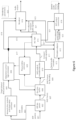
- Figure 6 is a more detailed depiction of the jitter buffer management system 500 for IVAS.
- RTP packets 601 are depicted as being received and passed to the RTP de-packer 602 which may be arranged to extract the IVAS frames 607.
- the RTP de-packer 602 may also be arranged to obtain from the RTP streams so called RTP metadata 603 which can be used to update IP network metrics such as frame receive statistics which in turn may be used to estimate network jitter.
- RTP metadata 603 may be passed to the Network jitter analysis and target delay estimator 604 where the RTP metadata 603, comprising packet timestamp and sequence information, may be analysed to provide a target playout delay parameter 605 for use in the adaption control logic processor 606.
- the IVAS frames 607 as obtained by the de-packing process of the RTP de-packer 602 are depicted in Figure 6 as being passed to the de-jitter buffer 608.
- the de-jitter buffer 608 is arranged to store the IVAS frames 607 in a frame buffer ready for decoding by IVAS audio & metadata decoder 610.
- the de-jitter buffer 608 can also be arranged to perform frame-based delay adjustment on the stream of IVAS frames when instructed to by the adaption control logic processor 606, and also reorder the IVAS frames into a correct decoding order should they not arrive in the proper sequential order (for decoding.)
- the output from the de-jitter buffer 608, in other words IVAS frames for decoding 609, may be passed to the IVAS audio & metadata decoder 610.
- the IVAS audio decoder & metadata decoder 610 is arranged to decode the IVAS frames 609 into a decoded multichannel transport audio signal stream 611 (also referred to as the transport audio signal(s) and a MASA spatial audio metadata stream 613 (also referred to as spatial audio metadata).
- the MASA spatial audio metadata and decoded multichannel transport audio signal streams 613 and 611 may be passed on to subsequent processing blocks so that any time sequence adjustments to the respective signals may be performed.
- the respective stream 613 is passed to the metadata adaptor 612 and in the case of the decoded multichannel transport audio signal the respective stream 611 is passed to the multi-channel time scale modifier (MC TSM) 614.
- MC TSM multi-channel time scale modifier
- the MC TSM 614 is configured to time scale modify frames of the transport audio signals 611 under the direction of the adaption control logic processor 606. Basically, the MC TSM 614 performs the time stretching or time shortening of the transport audio signal(s) in the time domain in response to a time adjustment instruction provided by adaption control logic processor 606. The time adjustment instruction may be received by the MC TSM 614 along the control line 615 from the adaption control logic processor 606.
- the output from the MC TSM 614 i.e., frames of the time-adjusted transport audio signals 621, may be passed to the renderer 616, a processing block termed the EXT output constructor 618 and the metadata adaptor 612.
- the time-adjusted transport audio signal(s) 621 is used to assist in the adaption of the spatial audio metadata so that synchrony is better maintained.
- the metadata adaptor 612 is essentially arranged to receive the spatial audio metadata parameters 613 corresponding to the frames of the transport audio signal(s) 611 that are delivered to the MC TSM 614, adapt these spatial audio metadata parameters 613 in accordance with the time adjustment instructions as provided by the adaption control logic processor 606, and maintain time synchrony with the time-adjusted transport audio signal(s) 621.
- the metadata adaptor 612 is configured to receive the time-adjusted transport audio signal(s) 621 and the time adjustment instructions from the adaption control logic processor 606 along the signal line 617.
- the metadata adaptor 612 may then be arranged to produce time-adapted spatial audio metadata which has time synchrony with the time-adjusted transport audio signals 621.
- the time adapted spatial audio metadata is depicted as the signal 623 in Figure 6 and is shown as being passed to both the renderer 616 and EXT output constructor 618.
- the renderer 616 which can receive the time-adjusted transport audio signals 621 and the time adapted spatial audio metadata 623 and render said signals into a multichannel spatial audio output signal.
- the rendering may be performed in accordance with the rendering parameters 625.
- the renderer 616 is also shown as receiving a signal from the adaption control logic processor 606 along the signal line 619.
- FIG. 6 also shows a further output processing function in the form of the EXT output constructor 618.
- This processing function simply takes the time-adjusted transport audio signals 621 and the time adapted spatial audio metadata 623 and "packages" the signals into a single frame format suitable for outputting from a device, in other words a "spatial audio format” suitable for storage as a file type and the like.
- the purpose of the EXT output constructor 618 is to output the spatial audio format as it was decoded with minimal changes to conform to a spatial audio format specification. It can be then stored, re-encoded, mixed, or rendered with an external renderer.
- the jitter buffer management system for IVAS also comprises the adaption control logic processor 606.
- the adaption control logic processor 606 is responsible for providing the time adjustment instructions to other processing blocks in the system. This may be realised by the adaption control logic processor 606 receiving a target delay estimation/parameter 605 from the network jitter analysis and target delay estimator 604 and the current playout delay from the playout delay estimator 620 and using this information to choose the method for playout delay adjustment to reach the target playout delay. This may be provided to the various processing blocks in the form of time adjustment instructions. The various processing blocks may then each individually utilise the received time adjustment instructions to perform appropriate actions so that the audio output from the renderer 616 is played out with the correct time.
- the following functions may be configured to receive time adjustment instructions from the adaption control logic processor 606; de-jitter buffer 608, metadata adaptor 612, MC TSM 614, and the renderer 616.
- the playout delay estimator 620 provides estimate of the current playout delay to 606 based on the information received from 608 and 614.
- the metadata adaptor 612 is arranged to adjust the spatial audio metadata 613 in accordance with the time adjustment instructions (playout delay time) whilst maintaining synchrony with the time-adjusted transport audio signals 621.
- Figure 7 shows the metadata adaptor 612 according to embodiments in further detail.
- the metadata adaptor 612 takes as input the time adjustment instructions 617 from the adaption control logic processor 606. This input may then be passed to the slot to subframe mapper 702.
- the time adjustment instructions 617 may contain information pertaining to the number of subframes and hence audio time slots that are to be rendered. For the sake of brevity this information can be referred to as "slot adaptation info.”
- the original IVAS frame can be divided into a number of subframes with each subframe being divided into a further number of audio slots.
- One such example comprises a 20 ms frame divided into 4 equal length subframes, with each subframe being evenly divided into 4 audio slots giving a total of 16 audio slots at 1.25 ms each.
- the "slot adaptation info" may contain a parameter giving the number of audio slots N slots present in the time-adjusted transport audio signals 621, which in turn provides the number of subframes in the signal and consequently the frame size of the time-adjusted transport audio signals 621. This information may then be used to adapt the spatial audio parameters sets which are currently time aligned with the subframes of the original IVAS frame to being time aligned with the subframes of the time-adjusted transport audio signals 621.
- original IVAS frame refers to the size of the IVAS frame before any time shortening/lengthening has taken place. So, it refers to the frames of the transport audio signal(s).
- the parameter N slots may be different from the default number of slots in an original IVAS frame N slots _ default , with the default number of slots being the number of slots in an original IVAS frame before the time stretching/shortening process.
- N slots_default is 16 audio slots.
- the slot subframe mapper 702 can be arranged to map the "original" default number of slots N slots _ default of the original IVAS frame, to a different number of slots N slots distributed across the same number of subframes as the original IVAS frame. This has the outcome of mapping the slots/subframes of the adapted IVAS frame to the standard IVAS frame. This results in a pattern of mapped slots where some of the subframes (of the original IVAS frame) have either more or less mapped slots depending on whether the adapted slot number N slots is greater or less than the original number of slots N slots-default . For instance, if N slots ⁇ N slots_default then the process is a waveform shortening or output play speeding up operation, and if N slots > N slots _ default then the process is a waveform lengthening or output play slowing down operation.
- the slot to subframe mapper 702 may be arranged to map the N slots time slots of the adapted IVAS frame to the subframes of the original IVAS frame to produce a map for mapping a time slot of the adapted IVAS frame to a subframe of the original IVAS frame.
- mapping of each slot associated with the time adapted transport audio signal(s) 621 (adapted IVAS frame) to a subframe of the original IVAS frame is performed on the premise that the assigned subframe (in the original IVAS frame) best matches the temporal position of the slot in the time adapted transport audio signal(s) 621 (adapted IVAS frame).
- each subframe comprises a set of spatial audio parameters.
- each group of four audio slots in the original IVAS frame is associated with the spatial audio parameter set of one of the subframes. Therefore, the consequence of slot to subframe mapping process may be viewed as associating different groups of slots with the spatial audio parameter sets of the original IVAS frame.
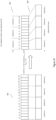
- Figure 8 shows an example subframe to slot mapping process when the adapted slot number N slots is 12 and the original number of slots N slots _ default is 16.
- this Figure 8 depicts an example of waveform shortening (decreasing the playing out time).
- the relationship between slots to subframes for the original IVAS frame, where every 4 slots is mapped to a subframe is shown as 801 in Figure 8 , i.e., slots s1 to s4 are mapped to subframe 1, slots s5 to s8 are mapped to subframe 2, slots s9 to s12 are mapped to subframe 3 and slots s13 to s16 are mapped to subframe 4.
- the result of the mapping process where 12 slots are mapped to the 4 subframes of the original IVAS frame may be shown as 802 in Figure 8 .
- the slot to mapping process has resulted in the first three slots (s1, s2, s3) being mapped to first subframe.
- the fourth and fifth slots (s4, s5) have been mapped to the second subframe.
- Slots s6, s7, s8 are mapped to subframe 3.
- slots s9, s10, s11 and s12 are now mapped to subframe 4.
- the above subframe to slot mapping process can be performed by initially dividing the number of adapted slots N slots into two contiguous regions.
- the second region is made up of the remaining slots s1 to s8, i.e., the run of slots starting from the beginning of the frame, and going up to slot number ( N slots -N slots _ end ) .
- the subframe to slot mapping process take the N slots_end highest ordered slots of the adapted IVAS frame and matches each them on an ordered one-to-one bases to the N slots_end highest ordered slots of the original IVAS frame subframes and consequently the subframes associated with these slots.
- This processing step may be illustrated by referring to the example of Figure 8 , where the slots of the adapted IVAS frame s9, s10, s11 and s12 are mapped on a one-to-one basis to the subframe having the 4 highest slots of the original IVAS frame s13, s14, s15 and s16, i.e., subframe 4.
- M slot_sf ( m ) first is the subframe to slot mapping function which gives the subframe to slot map for the first region. This function returns the mapped subframe number (with respect to the original IVAS frame) for each slot m of the first region of slots of the adapted IVAS frame.
- N slots,remdefault is the number of original slots remaining after the number of N slots,end have been removed.
- N slots , remdefault N slots , default ⁇ N slots , end
- Figure 9 shows an example subframe to slot mapping process when the adapted slot number N slots is 20 and again the original number of slots N slots _ default is 16.
- Figure 9 depicts an example of waveform extending (increasing the playing out time).
- the distribution of slots in the standard IVAS frame is shown as 901 in Figure 9 and the result of the slot to subframe mapping process where 20 slots (and hence 5 subframes of the time adapted transport audio signal(s) 621 frame (adapted IVAS frame) are mapped to the 4 subframes of the standard IVAS frame is shown as 902 in Figure 9 .
- N slots,end 12
- 903 the relationship between the subframes of the time adapted transport audio signals 621 frame and the N slots slots.
- the second region of slots is therefore given by the lowest ordered contiguous run of slots from the first slot, s1 to the highest slot with the slot number N slots - N slots,end .
- the slot to subframe mapping process then maps this contiguous run of lowest ordered slots by distributing them across a number of the subframes, starting from the lowest numbered subframe. For instances, when N slots > N slots_default , i.e., a period of waveform lengthening, the second region of slots (of the adapted IVAS frame) may be distributed across the first subframe and subsequent subframes up to and including the subframe to which the lowest ordered slot from the first region is mapped. For instances, when N slots ⁇ N slots_default , i.e., a period of waveform shortening, the second region of slots (of the adapted IVAS frame) may be distributed across all subframes of the IVAS frame.
- M slot-sf ( m ) second is the subframe to slot mapping function which gives the subframe (of the original IVAS frame) to slot map for the second region. This function returns the mapped subframe number (of the original IVAS frame) for each slot m of the second region of slots of the adapted IVAS frame.
- the output from the slot to subframe mapper 702 is the combined slot to subframe map for both the first and second regions and may be referred to as M slot-sf ( m ) .
- This output is depicted as 701 in Figure 7 .
- the slot to subframe mapper 702 may be arranged to distribute the N slots of the adapted IVAS frame across the subframes of the original IVAS frame in a different manner to the above embodiments. In these embodiments, there may be no mapping between the N slots slots of the adapted IVAS frame and the N slots_default slots of the original IVAS frame. Instead, the N slots slots of the adapted IVAS frame may be mapped directly to the subframes of the original IVAS frame using the following routine.
- N slots,sf is equivalent to L sf in the above embodiment, which is 4 for the standard IVAS frame
- L map may be the same for all subframes of the original IVAS frame.
- the N slots of the adapted IVAS frame may be distributed evenly across the subframes of the original IVAS frame.
- N.B. for the standard IVAS frame size i sf will take the values 1 to 4, corresponding to subframes 1 to 4 of the original IVAS frame.
- Figure 10 shows an example subframe to slot mapping process according to these embodiments where the adapted slot number N slots is 12 and the original number of slots N slots _ default is 16.
- the relationship between slots and subframes for the original IVAS frame, where every 4 slots is mapped to a subframe, is shown as 1001 in Figure 10 .
- the result of the mapping process where 12 slots of the adapted IVAS frame are mapped to the 4 subframes of the original IVAS frame are shown as 1002 in Figure 10 . It can be seen that the 12 slots of the adapted IVAS frame have been evenly distributed across the 4 subframes of the original IVAS frame, i.e.
- Figure 11 depicts further examples of the subframe to slot mapping process according these embodiments where the adapted slot number N slots are 13 and 14 and the original number of slots N slots_default is 16.
- the result of the mapping process where 13 slots of the adapted IVAS frame are mapped to the 4 subframes of the original IVAS frame is shown as 1101 in Figure 11 .
- the output 701 in Figure 7 from the slot to subframe mapper 702 is the above slot to subframe map M slot_sf ( m ).
- the energy determiner 704 which is shown as receiving the time adjustment instructions 617 and the time-adjusted transport audio signal(s) 621 frame (adapted IVAS frame).
- the function of the energy determiner 704 is to determine the energy of the adapted IVAS frame on a slot-by-slot basis according to the number of slots N slots .
- the energy determiner 704 takes in frame length of N slots *slot width (1.25 ms) of the time-adjusted transport audio signals 621, i.e., an adapted IVAS frame and effectively divides the frame into N slots time slots and then determines the energy across all the audio signals of the adapted IVAS frame for each slot.
- q is the number of time shifted transport audio signals/channels in the signal 621.
- the output from the energy determiner 704 is the energy E for each time slot m for an adapted IVAS frame. This is shown as the output 703 in Figure 7 .
- subframe-to-subframe map determiner 706 which is depicted as receiving the energy E for each time slot m of the adapted IVAS frame 703 and the slot to subframe map M slot-sf ( m ) 701.
- the function of the subframe-to-subframe map determiner 706 is to determine, for each subframe of the adapted IVAS frame, a subframe from the original IVAS frame whose associated spatial audio parameters most closely align with the audio signal of the subframe of the adapted IVAS frame.
- This may be performed in order to provide a map whereby a subframe of the adapted IVAS frame is mapped to a subframe of the original IVAS frame.
- the subframe-to-subframe mapping determiner 706 may be arranged to use the map for mapping a time slot of the adapted IVAS frame to a subframe of the original IVAS frame to produce a map for mapping a subframe of the adapted IVAS frame to a subframe of the original IVAS frame.
- this function may be performed by the subframe-to-subframe map determiner 703 being arranged to use the slot to subframe maps 701 and the energy E for each time slot m 703 to determine an energy to subframe map for each subframe of the original IVAS frame.
- the energy to subframe map determiner 706 determines for each subframe of the original IVAS frame the energy of the adapted IVAS frame slots which were mapped to the subframe.
- M E-sf ( n ) is the energy of slots mapped to a subframe n of the original IVAS frame, where the adapted IVAS frame slots mapped to the subframe n are given by the slot to subframe mapping M slot-sf ( m ) and where m n A is the list of slots mapped to subframe n (of the original IVAS frame), m n A (0) represents the first slot mapped to subframe n and m n A ( N - 1) the last slot mapped to subframe n, where N represents the number of slots in subframe n A .
- the understanding of the above equation may be enhanced by returning to the example of Figure 8 .
- the next step performed by the subframe-to-subframe mapper 702 is to determine for a subframe n A of the adapted IVAS frame the subframe n max (of the original IVAS frame) which gives the maximum energy to subframe value of all the M E-sf ( n ) values which comprise the slots of the subframe n A of the adapted IVAS frame. This may be performed for all subframes of the adapted IVAS frame.
- the pseudo code for this step may have the following form:
- the subframe n ewm may more often chosen from the beginning of the slot to subframe map section M slot-sf ( m ), where m ⁇ [ m n A (0) , m n A ( N - 1)].
- subframe-to-subframe mapping function may be performed according to the flow chart presented in Figure 12 .
- the number of subframes of the adapted IVAS frame may be determined or communicated to the subframe-to-subframe map determiner 706.
- the number of subframes in the adapted IVAS frame N A may be based on the premise that each subframe comprises the same number of slots as each subframe of the original IVAS frame.
- the step of determining/acquiring the number of subframes in an adapted IVAS frame is shown in Figure 12 as the processing step 1201.
- n A 0: N A - 1.
- the subframe level processing loop comprises the steps 1207 to 1211.
- the total energy for the first subframe of the adapted IVAS signal will comprise the sum of the slot energies E (0) to E (3) for slots s1 to s4, (i.e. m 1 (0) to m 1 (3)).
- the total energy for the second subframe of the adapted IVAS signal will comprise the sum of the slot energies E (4) to E (7) for slots s5 to s8, (i.e. m 2 (0) to m 2 (3)).
- the total energy for the third subframe will comprise the totals for E (8) to E (11) for slots s9 to s12, (i.e. m 3 (0) to m 3 (3)).
- the final slot s13 may either be processed as a non-full subframe, or it may be buffered for the next decoded IVAS frame.
- the step of determining the total energy for the slots of the subframe of the adapted IVAS frame is shown as processing step 1207 in Figure 12 .
- the next step of the subframe processing loop initialises an accumulative energy factor E cum for the subframe of the adapted IVAS frame. This is shown as processing step 1209 in Figure 12 .
- This is shown as the processing step 1211 and comprises the steps 1213 to 1217.
- the first step of the slot level processing loop adds the energy of a current slot E ( k ) to the accumulative energy E cum . This is shown as step 1213 in Figure 12 .
- the slot level processing loop then checks whether the accumulative energy E cum is greater than E tot /2 for the subframe. This is shown as the processing step 1215.
- step 1215 If it was determined at step 1215 that the above criterion had been met, the slot level processing loop progresses to the processing step 1217.
- the index k (which has led to the above criterion being met) is used to map a subframe of the original IVAS frame to the subframe of the adapted IVAS frame. This may be performed by taking the subframe of the original IVAS frame which houses the index k and assigns this subframe [of the original IVAS frame] to the subframe n A [of the adapted IVAS frame]. As mentioned above the mapping (or relationship) between slots of the adapted IVAS frame and subframes of the original IVAS frame is given by the mapping function M slot-sf ( m ) .
- step 1215 if the criterium is not met, i.e. E cum is not greater than E tot /2 for the subframe n A then the process selects the next slot of the subframe of the adapted IVAS frame and proceeds to steps 1213 and 1215.
- the result of the processing steps of Figure 12 is the subframe-to-subframe map/table M sf-sf with an entry for all subframes n A of the of the adapted IVAS frame.
- This subframe-to-subframe map M sf-sf may then be used to obtain the one-to-one mapping between the optimum subframe of the original IVAS frame for each subframe of the adapted IVAS frame.
- the subframe-to-subframe map M sf-sf may form the output 705 of the subframe-to-subframe map determiner 706.
- the spatial audio metadata adaptor 708 which can be arranged to receive the spatial audio metadata 613 and the subframe-to-subframe map M sf-sf 705 and produce as output the time adapted spatial audio metadata 623.
- the spatial audio metadata adaptor 708 is arranged to assign a spatial audio parameter set of the original IVAS frame to each subframe of the adapted IVAS frame n A by using the subframe-to-subframe map M sf-sf 705. For each entry n A of the subframe-to-subframe map M sf-sf 705 there is a corresponding original IVAS subframe index n. The index n may then be used to assign the spatial audio parameter set of subframe n of the original IVAS frame to subframe n A of the adapted IVAS frame or in other words subframe n A of the time-adjusted transport audio signal(s) 621 frame.
- this mechanism can be repeated for the other spatial parameters in the MASA spatial audio parameter set to give the adapted MASA spatial audio parameter set for subframe n A of the time-adjusted transport audio signal(s) 621 frame.
- the time adapted spatial audio metadata 623 output therefore may comprise spatial audio parameter set for each subframe n A of the time-adjusted transport audio signal(s) 621 frame.
- the audio signal and the metadata may be asynchronized after decoding and the synchronization step is performed after JBM process and the output of the audio and metadata.
- a delay may be needed to allow use of correct slot energy in the weighting process. This may be achieved by simply delaying the audio signal or the original metadata as necessary.
- a ring buffer may be used for such a purpose.
- the process of selecting metadata and calculating energies may be done in time-frequency domain.
- the metadata selection may be done for each subframe & frequency band combination separately using time slots and frequency bands.
- the process of forming the subframe-to-subframe map M sf-sf 705 may use signal energy only for one of the cases, waveform extending (increasing the playing out time) or waveform shortening (decreasing the playing out time).
- the audio and metadata format may be some other format than MASA format, or the audio and metadata format is derived from some other format during encoding and decoding in codec.
- the energy of some slots may be missing or unobtainable, e.g., due to asynchrony.
- the energy of these slots can be approximated from the other slots in current frame and in history that have obtainable energy value.
- An example of such approximation is the average energy value of the other slots with obtainable energy value which may be assigned as the energy value of any slot with missing energy.
- FIG. 13 is shown an example system within which some embodiments can be implemented.
- the transport audio signals 102 and the spatial metadata 104 are passed to an encoder 1301 which generates an encoded bitstream 1302.
- the encoded bitstream 1302 is received by the decoder 1303 which is configured to generate a spatial audio output 1304.
- the transport audio signals 102 and the spatial metadata 104 can be obtained in the form of a MASA stream.
- the MASA stream can, for example, originate from a mobile device (containing a microphone array), or as an alternative example, it may have been created by an audio server that has potentially processed a MASA stream in some way.
- the encoder 1301 can furthermore, in some embodiments, be an IVAS encoder.
- the decoder 1303, in some embodiments, can be configured to directly output the spatial audio output 1304 to be rendered by an external renderer, or edited/processed by an audio server.
- the decoder 1303 comprises a suitable renderer, which is configured to render the output in a suitable form, such as binaural audio signals or multichannel loudspeaker signals (such as 5.1 or 7.1+4 channel format), which are also examples of spatial audio output 1304.
- the device may be any suitable electronics device or apparatus.
- the device 1400 is a mobile device, user equipment, tablet computer, computer, audio playback apparatus, etc.
- the device may for example be configured to implement the encoder and/or decoder or any functional block as described above.
- the device 1400 comprises at least one processor or central processing unit 1407.
- the processor 1407 can be configured to execute various program codes such as the methods such as described herein.
- the device 1400 comprises at least one memory 1411.
- the at least one processor 1407 is coupled to the memory 1411.
- the memory 1411 can be any suitable storage means.
- the memory 1411 comprises a program code section for storing program codes implementable upon the processor 1407.
- the memory 1411 can further comprise a stored data section for storing data, for example data that has been processed or to be processed in accordance with the embodiments as described herein. The implemented program code stored within the program code section and the data stored within the stored data section can be retrieved by the processor 1407 whenever needed via the memory-processor coupling.
- the device 1400 comprises a user interface 1405.
- the user interface 1405 can be coupled in some embodiments to the processor 1407.
- the processor 1407 can control the operation of the user interface 1405 and receive inputs from the user interface 1405.
- the user interface 1405 can enable a user to input commands to the device 1400, for example via a keypad.
- the user interface 1405 can enable the user to obtain information from the device 1400.
- the user interface 1405 may comprise a display configured to display information from the device 1400 to the user.
- the user interface 1405 can in some embodiments comprise a touch screen or touch interface capable of both enabling information to be entered to the device 1400 and further displaying information to the user of the device 1400.
- the user interface 1405 may be the user interface for communicating.
- the device 1400 comprises an input/output port 1409.
- the input/output port 1409 in some embodiments comprises a transceiver.
- the transceiver in such embodiments can be coupled to the processor 1407 and configured to enable a communication with other apparatus or electronic devices, for example via a wireless communications network.
- the transceiver or any suitable transceiver or transmitter and/or receiver means can in some embodiments be configured to communicate with other electronic devices or apparatus via a wire or wired coupling.
- the transceiver can communicate with further apparatus by any suitable known communications protocol.
- the transceiver can use a suitable radio access architecture based on long term evolution advanced (LTE Advanced, LTE-A) or new radio (NR) (or can be referred to as 5G), universal mobile telecommunications system (UMTS) radio access network (UTRAN or E-UTRAN), long term evolution (LTE, the same as E-UTRA), 2G networks (legacy network technology), wireless local area network (WLAN or Wi-Fi), worldwide interoperability for microwave access (WiMAX), Bluetooth ® , personal communications services (PCS), ZigBee ® , wideband code division multiple access (WCDMA), systems using ultra-wideband (UWB) technology, sensor networks, mobile ad-hoc networks (MANETs), cellular internet of things (IoT) RAN and Internet Protocol multimedia subsystems (IMS), any other suitable option and/or any combination thereof.
- LTE Advanced long term evolution advanced
- NR new radio
- 5G long term evolution
- the transceiver input/output port 1409 may be configured to receive the signals.
- the device 1400 may be employed as at least part of the synthesis device.
- the input/output port 1409 may be coupled to headphones (which may be a headtracked or a non-tracked headphones) or similar and loudspeakers.
- the various embodiments of the invention may be implemented in hardware or special purpose circuits, software, logic or any combination thereof.
- some aspects may be implemented in hardware, while other aspects may be implemented in firmware or software which may be executed by a controller, microprocessor or other computing device, although the invention is not limited thereto.
- firmware or software which may be executed by a controller, microprocessor or other computing device, although the invention is not limited thereto.
- While various aspects of the invention may be illustrated and described as block diagrams, flow charts, or using some other pictorial representation, it is well understood that these blocks, apparatus, systems, techniques or methods described herein may be implemented in, as non-limiting examples, hardware, software, firmware, special purpose circuits or logic, general purpose hardware or controller or other computing devices, or some combination thereof.
- the embodiments of this invention may be implemented by computer software executable by a data processor of the mobile device, such as in the processor entity, or by hardware, or by a combination of software and hardware.
- any blocks of the logic flow as in the Figures may represent program steps, or interconnected logic circuits, blocks and functions, or a combination of program steps and logic circuits, blocks and functions.
- the software may be stored on such physical media as memory chips, or memory blocks implemented within the processor, magnetic media such as hard disk or floppy disks, and optical media such as for example DVD and the data variants thereof, CD.
- the memory may be of any type suitable to the local technical environment and may be implemented using any suitable data storage technology, such as semiconductor-based memory devices, magnetic memory devices and systems, optical memory devices and systems, fixed memory and removable memory.
- the data processors may be of any type suitable to the local technical environment, and may include one or more of general-purpose computers, special purpose computers, microprocessors, digital signal processors (DSPs), application specific integrated circuits (ASIC), gate level circuits and processors based on multi-core processor architecture, as non-limiting examples.
- Embodiments of the inventions may be practiced in various components such as integrated circuit modules.
- the design of integrated circuits is by and large a highly automated process.
- Complex and powerful software tools are available for converting a logic level design into a semiconductor circuit design ready to be etched and formed on a semiconductor substrate.
- Programs such as those provided by Synopsys, Inc. of Mountain View, California and Cadence Design, of San Jose, California automatically route conductors and locate components on a semiconductor chip using well established rules of design as well as libraries of pre-stored design modules.
- the resultant design in a standardized electronic format (e.g., Opus, GDSII, or the like) may be transmitted to a semiconductor fabrication facility or "fab" for fabrication.
- circuitry may refer to one or more or all of the following:
- circuitry also covers an implementation of merely a hardware circuit or processor (or multiple processors) or portion of a hardware circuit or processor and its (or their) accompanying software and/or firmware.
- circuitry also covers, for example and if applicable to the particular claim element, a baseband integrated circuit or processor integrated circuit for a mobile device or a similar integrated circuit in server, a cellular network device, or other computing or network device.
- non-transitory is a limitation of the medium itself (i.e., tangible, not a signal) as opposed to a limitation on data storage persistency (e.g., RAM vs. ROM).
Landscapes
- Engineering & Computer Science (AREA)
- Physics & Mathematics (AREA)
- Computational Linguistics (AREA)
- Signal Processing (AREA)
- Health & Medical Sciences (AREA)
- Audiology, Speech & Language Pathology (AREA)
- Human Computer Interaction (AREA)
- Acoustics & Sound (AREA)
- Multimedia (AREA)
- Mathematical Physics (AREA)
- Stereophonic System (AREA)
Priority Applications (1)
| Application Number | Priority Date | Filing Date | Title |
|---|---|---|---|
| EP23177532.1A EP4475122A1 (de) | 2023-06-06 | 2023-06-06 | Anpassung räumlicher audioparameter für jitterpufferverwaltung |
Applications Claiming Priority (1)
| Application Number | Priority Date | Filing Date | Title |
|---|---|---|---|
| EP23177532.1A EP4475122A1 (de) | 2023-06-06 | 2023-06-06 | Anpassung räumlicher audioparameter für jitterpufferverwaltung |
Publications (1)
| Publication Number | Publication Date |
|---|---|
| EP4475122A1 true EP4475122A1 (de) | 2024-12-11 |
Family
ID=86692800
Family Applications (1)
| Application Number | Title | Priority Date | Filing Date |
|---|---|---|---|
| EP23177532.1A Pending EP4475122A1 (de) | 2023-06-06 | 2023-06-06 | Anpassung räumlicher audioparameter für jitterpufferverwaltung |
Country Status (1)
| Country | Link |
|---|---|
| EP (1) | EP4475122A1 (de) |
Citations (4)
| Publication number | Priority date | Publication date | Assignee | Title |
|---|---|---|---|---|
| US20080114606A1 (en) * | 2006-10-18 | 2008-05-15 | Nokia Corporation | Time scaling of multi-channel audio signals |
| US20140140516A1 (en) * | 2011-07-15 | 2014-05-22 | Huawei Technologies Co., Ltd. | Method and apparatus for processing a multi-channel audio signal |
| US20200265851A1 (en) * | 2017-11-17 | 2020-08-20 | Fraunhofer-Gesellschaft zur Förderung der angewandten Forschung e.V. | Apparatus and Method for encoding or Decoding Directional Audio Coding Parameters Using Quantization and Entropy Coding |
| WO2021255327A1 (en) * | 2020-06-18 | 2021-12-23 | Nokia Technologies Oy | Managing network jitter for multiple audio streams |
-
2023
- 2023-06-06 EP EP23177532.1A patent/EP4475122A1/de active Pending
Patent Citations (4)
| Publication number | Priority date | Publication date | Assignee | Title |
|---|---|---|---|---|
| US20080114606A1 (en) * | 2006-10-18 | 2008-05-15 | Nokia Corporation | Time scaling of multi-channel audio signals |
| US20140140516A1 (en) * | 2011-07-15 | 2014-05-22 | Huawei Technologies Co., Ltd. | Method and apparatus for processing a multi-channel audio signal |
| US20200265851A1 (en) * | 2017-11-17 | 2020-08-20 | Fraunhofer-Gesellschaft zur Förderung der angewandten Forschung e.V. | Apparatus and Method for encoding or Decoding Directional Audio Coding Parameters Using Quantization and Entropy Coding |
| WO2021255327A1 (en) * | 2020-06-18 | 2021-12-23 | Nokia Technologies Oy | Managing network jitter for multiple audio streams |
Non-Patent Citations (1)
| Title |
|---|
| VILKAMO, J.BACKSTROM, T.KUNTZ, A.: "Optimized covariance domain framework for time-frequency processing of spatial audio", JOURNAL OF THE AUDIO ENGINEERING SOCIETY, vol. 61, no. 6, 2013, pages 403 - 411, XP093021901 |
Similar Documents
| Publication | Publication Date | Title |
|---|---|---|
| US20260012742A1 (en) | Spatial Audio Representation and Rendering | |
| WO2015131063A1 (en) | Object-based audio loudness management | |
| EP3818730A1 (de) | Signalisierung und synthese von energiekennzahlen | |
| US20210250717A1 (en) | Spatial audio Capture, Transmission and Reproduction | |
| US20250157475A1 (en) | Parametric spatial audio rendering | |
| EP4627809A1 (de) | Binaurale audiowiedergabe von räumlichem audio | |
| EP4475122A1 (de) | Anpassung räumlicher audioparameter für jitterpufferverwaltung | |
| AU2024226319A1 (en) | Diffuse-preserving merging of masa and ism metadata | |
| WO2022223133A1 (en) | Spatial audio parameter encoding and associated decoding | |
| US20240236601A9 (en) | Generating Parametric Spatial Audio Representations | |
| JP2026511173A (ja) | 低コーディングレートのパラメータ空間オーディオ符号化 | |
| WO2021255327A1 (en) | Managing network jitter for multiple audio streams | |
| CN118946930A (zh) | 参数化空间音频编码 | |
| EP4627572B1 (de) | Parametrische räumliche audiokodierung | |
| WO2025078226A1 (en) | Parametric spatial audio decoding with pass-through mode | |
| GB2636377A (en) | Frame erasure recovery | |
| JP2025540764A (ja) | パラメトリック空間オーディオ符号化 | |
| EP4690188A1 (de) | Codierung von out-of-sync-metadaten auf rahmenebene | |
| WO2024175320A1 (en) | Priority values for parametric spatial audio encoding | |
| WO2025223950A1 (en) | Signalling of pass-through mode in spatial audio coding | |
| US20240274137A1 (en) | Parametric spatial audio rendering | |
| WO2024165271A1 (en) | Audio rendering of spatial audio | |
| GB2636541A (en) | Decoding of frame-level out-of-sync metadata |
Legal Events
| Date | Code | Title | Description |
|---|---|---|---|
| PUAI | Public reference made under article 153(3) epc to a published international application that has entered the european phase |
Free format text: ORIGINAL CODE: 0009012 |
|
| STAA | Information on the status of an ep patent application or granted ep patent |
Free format text: STATUS: THE APPLICATION HAS BEEN PUBLISHED |
|
| AK | Designated contracting states |
Kind code of ref document: A1 Designated state(s): AL AT BE BG CH CY CZ DE DK EE ES FI FR GB GR HR HU IE IS IT LI LT LU LV MC ME MK MT NL NO PL PT RO RS SE SI SK SM TR |
|
| STAA | Information on the status of an ep patent application or granted ep patent |
Free format text: STATUS: REQUEST FOR EXAMINATION WAS MADE |
|
| 17P | Request for examination filed |
Effective date: 20250611 |
|
| STAA | Information on the status of an ep patent application or granted ep patent |
Free format text: STATUS: EXAMINATION IS IN PROGRESS |