EP4475248A1 - Nichtwässrige elektrolytlösung und nichtwässrige sekundärbatterie - Google Patents
Nichtwässrige elektrolytlösung und nichtwässrige sekundärbatterie Download PDFInfo
- Publication number
- EP4475248A1 EP4475248A1 EP23882644.0A EP23882644A EP4475248A1 EP 4475248 A1 EP4475248 A1 EP 4475248A1 EP 23882644 A EP23882644 A EP 23882644A EP 4475248 A1 EP4475248 A1 EP 4475248A1
- Authority
- EP
- European Patent Office
- Prior art keywords
- electrolyte solution
- negative electrode
- aqueous
- positive electrode
- secondary battery
- Prior art date
- Legal status (The legal status is an assumption and is not a legal conclusion. Google has not performed a legal analysis and makes no representation as to the accuracy of the status listed.)
- Pending
Links
Images
Classifications
-
- H—ELECTRICITY
- H01—ELECTRIC ELEMENTS
- H01M—PROCESSES OR MEANS, e.g. BATTERIES, FOR THE DIRECT CONVERSION OF CHEMICAL ENERGY INTO ELECTRICAL ENERGY
- H01M10/00—Secondary cells; Manufacture thereof
- H01M10/05—Accumulators with non-aqueous electrolyte
- H01M10/056—Accumulators with non-aqueous electrolyte characterised by the materials used as electrolytes, e.g. mixed inorganic/organic electrolytes
- H01M10/0564—Accumulators with non-aqueous electrolyte characterised by the materials used as electrolytes, e.g. mixed inorganic/organic electrolytes the electrolyte being constituted of organic materials only
- H01M10/0566—Liquid materials
- H01M10/0569—Liquid materials characterised by the solvents
-
- H—ELECTRICITY
- H01—ELECTRIC ELEMENTS
- H01M—PROCESSES OR MEANS, e.g. BATTERIES, FOR THE DIRECT CONVERSION OF CHEMICAL ENERGY INTO ELECTRICAL ENERGY
- H01M10/00—Secondary cells; Manufacture thereof
- H01M10/05—Accumulators with non-aqueous electrolyte
- H01M10/052—Li-accumulators
-
- H—ELECTRICITY
- H01—ELECTRIC ELEMENTS
- H01M—PROCESSES OR MEANS, e.g. BATTERIES, FOR THE DIRECT CONVERSION OF CHEMICAL ENERGY INTO ELECTRICAL ENERGY
- H01M10/00—Secondary cells; Manufacture thereof
- H01M10/05—Accumulators with non-aqueous electrolyte
- H01M10/052—Li-accumulators
- H01M10/0525—Rocking-chair batteries, i.e. batteries with lithium insertion or intercalation in both electrodes; Lithium-ion batteries
-
- H—ELECTRICITY
- H01—ELECTRIC ELEMENTS
- H01M—PROCESSES OR MEANS, e.g. BATTERIES, FOR THE DIRECT CONVERSION OF CHEMICAL ENERGY INTO ELECTRICAL ENERGY
- H01M10/00—Secondary cells; Manufacture thereof
- H01M10/05—Accumulators with non-aqueous electrolyte
- H01M10/056—Accumulators with non-aqueous electrolyte characterised by the materials used as electrolytes, e.g. mixed inorganic/organic electrolytes
- H01M10/0564—Accumulators with non-aqueous electrolyte characterised by the materials used as electrolytes, e.g. mixed inorganic/organic electrolytes the electrolyte being constituted of organic materials only
- H01M10/0566—Liquid materials
- H01M10/0567—Liquid materials characterised by the additives
-
- H—ELECTRICITY
- H01—ELECTRIC ELEMENTS
- H01M—PROCESSES OR MEANS, e.g. BATTERIES, FOR THE DIRECT CONVERSION OF CHEMICAL ENERGY INTO ELECTRICAL ENERGY
- H01M10/00—Secondary cells; Manufacture thereof
- H01M10/05—Accumulators with non-aqueous electrolyte
- H01M10/056—Accumulators with non-aqueous electrolyte characterised by the materials used as electrolytes, e.g. mixed inorganic/organic electrolytes
- H01M10/0564—Accumulators with non-aqueous electrolyte characterised by the materials used as electrolytes, e.g. mixed inorganic/organic electrolytes the electrolyte being constituted of organic materials only
- H01M10/0566—Liquid materials
- H01M10/0568—Liquid materials characterised by the solutes
-
- H—ELECTRICITY
- H01—ELECTRIC ELEMENTS
- H01M—PROCESSES OR MEANS, e.g. BATTERIES, FOR THE DIRECT CONVERSION OF CHEMICAL ENERGY INTO ELECTRICAL ENERGY
- H01M10/00—Secondary cells; Manufacture thereof
- H01M10/05—Accumulators with non-aqueous electrolyte
- H01M10/058—Construction or manufacture
-
- H—ELECTRICITY
- H01—ELECTRIC ELEMENTS
- H01M—PROCESSES OR MEANS, e.g. BATTERIES, FOR THE DIRECT CONVERSION OF CHEMICAL ENERGY INTO ELECTRICAL ENERGY
- H01M10/00—Secondary cells; Manufacture thereof
- H01M10/42—Methods or arrangements for servicing or maintenance of secondary cells or secondary half-cells
- H01M10/4235—Safety or regulating additives or arrangements in electrodes, separators or electrolyte
-
- H—ELECTRICITY
- H01—ELECTRIC ELEMENTS
- H01M—PROCESSES OR MEANS, e.g. BATTERIES, FOR THE DIRECT CONVERSION OF CHEMICAL ENERGY INTO ELECTRICAL ENERGY
- H01M10/00—Secondary cells; Manufacture thereof
- H01M10/42—Methods or arrangements for servicing or maintenance of secondary cells or secondary half-cells
- H01M10/44—Methods for charging or discharging
-
- H—ELECTRICITY
- H01—ELECTRIC ELEMENTS
- H01M—PROCESSES OR MEANS, e.g. BATTERIES, FOR THE DIRECT CONVERSION OF CHEMICAL ENERGY INTO ELECTRICAL ENERGY
- H01M4/00—Electrodes
- H01M4/02—Electrodes composed of, or comprising, active material
- H01M4/13—Electrodes for accumulators with non-aqueous electrolyte, e.g. for lithium-accumulators; Processes of manufacture thereof
- H01M4/131—Electrodes based on mixed oxides or hydroxides, or on mixtures of oxides or hydroxides, e.g. LiCoOx
-
- H—ELECTRICITY
- H01—ELECTRIC ELEMENTS
- H01M—PROCESSES OR MEANS, e.g. BATTERIES, FOR THE DIRECT CONVERSION OF CHEMICAL ENERGY INTO ELECTRICAL ENERGY
- H01M4/00—Electrodes
- H01M4/02—Electrodes composed of, or comprising, active material
- H01M4/13—Electrodes for accumulators with non-aqueous electrolyte, e.g. for lithium-accumulators; Processes of manufacture thereof
- H01M4/133—Electrodes based on carbonaceous material, e.g. graphite-intercalation compounds or CFx
-
- H—ELECTRICITY
- H01—ELECTRIC ELEMENTS
- H01M—PROCESSES OR MEANS, e.g. BATTERIES, FOR THE DIRECT CONVERSION OF CHEMICAL ENERGY INTO ELECTRICAL ENERGY
- H01M4/00—Electrodes
- H01M4/02—Electrodes composed of, or comprising, active material
- H01M4/13—Electrodes for accumulators with non-aqueous electrolyte, e.g. for lithium-accumulators; Processes of manufacture thereof
- H01M4/136—Electrodes based on inorganic compounds other than oxides or hydroxides, e.g. sulfides, selenides, tellurides, halogenides or LiCoFy
-
- H—ELECTRICITY
- H01—ELECTRIC ELEMENTS
- H01M—PROCESSES OR MEANS, e.g. BATTERIES, FOR THE DIRECT CONVERSION OF CHEMICAL ENERGY INTO ELECTRICAL ENERGY
- H01M4/00—Electrodes
- H01M4/02—Electrodes composed of, or comprising, active material
- H01M4/36—Selection of substances as active materials, active masses, active liquids
- H01M4/48—Selection of substances as active materials, active masses, active liquids of inorganic oxides or hydroxides
- H01M4/50—Selection of substances as active materials, active masses, active liquids of inorganic oxides or hydroxides of manganese
- H01M4/505—Selection of substances as active materials, active masses, active liquids of inorganic oxides or hydroxides of manganese of mixed oxides or hydroxides containing manganese for inserting or intercalating light metals, e.g. LiMn2O4 or LiMn2OxFy
-
- H—ELECTRICITY
- H01—ELECTRIC ELEMENTS
- H01M—PROCESSES OR MEANS, e.g. BATTERIES, FOR THE DIRECT CONVERSION OF CHEMICAL ENERGY INTO ELECTRICAL ENERGY
- H01M4/00—Electrodes
- H01M4/02—Electrodes composed of, or comprising, active material
- H01M4/36—Selection of substances as active materials, active masses, active liquids
- H01M4/48—Selection of substances as active materials, active masses, active liquids of inorganic oxides or hydroxides
- H01M4/52—Selection of substances as active materials, active masses, active liquids of inorganic oxides or hydroxides of nickel, cobalt or iron
- H01M4/525—Selection of substances as active materials, active masses, active liquids of inorganic oxides or hydroxides of nickel, cobalt or iron of mixed oxides or hydroxides containing iron, cobalt or nickel for inserting or intercalating light metals, e.g. LiNiO2, LiCoO2 or LiCoOxFy
-
- H—ELECTRICITY
- H01—ELECTRIC ELEMENTS
- H01M—PROCESSES OR MEANS, e.g. BATTERIES, FOR THE DIRECT CONVERSION OF CHEMICAL ENERGY INTO ELECTRICAL ENERGY
- H01M4/00—Electrodes
- H01M4/02—Electrodes composed of, or comprising, active material
- H01M4/36—Selection of substances as active materials, active masses, active liquids
- H01M4/58—Selection of substances as active materials, active masses, active liquids of inorganic compounds other than oxides or hydroxides, e.g. sulfides, selenides, tellurides, halogenides or LiCoFy; of polyanionic structures, e.g. phosphates, silicates or borates
-
- H—ELECTRICITY
- H01—ELECTRIC ELEMENTS
- H01M—PROCESSES OR MEANS, e.g. BATTERIES, FOR THE DIRECT CONVERSION OF CHEMICAL ENERGY INTO ELECTRICAL ENERGY
- H01M4/00—Electrodes
- H01M4/02—Electrodes composed of, or comprising, active material
- H01M4/36—Selection of substances as active materials, active masses, active liquids
- H01M4/58—Selection of substances as active materials, active masses, active liquids of inorganic compounds other than oxides or hydroxides, e.g. sulfides, selenides, tellurides, halogenides or LiCoFy; of polyanionic structures, e.g. phosphates, silicates or borates
- H01M4/5825—Oxygenated metallic salts or polyanionic structures, e.g. borates, phosphates, silicates, olivines
-
- H—ELECTRICITY
- H01—ELECTRIC ELEMENTS
- H01M—PROCESSES OR MEANS, e.g. BATTERIES, FOR THE DIRECT CONVERSION OF CHEMICAL ENERGY INTO ELECTRICAL ENERGY
- H01M4/00—Electrodes
- H01M4/02—Electrodes composed of, or comprising, active material
- H01M4/36—Selection of substances as active materials, active masses, active liquids
- H01M4/58—Selection of substances as active materials, active masses, active liquids of inorganic compounds other than oxides or hydroxides, e.g. sulfides, selenides, tellurides, halogenides or LiCoFy; of polyanionic structures, e.g. phosphates, silicates or borates
- H01M4/583—Carbonaceous material, e.g. graphite-intercalation compounds or CFx
-
- H—ELECTRICITY
- H01—ELECTRIC ELEMENTS
- H01M—PROCESSES OR MEANS, e.g. BATTERIES, FOR THE DIRECT CONVERSION OF CHEMICAL ENERGY INTO ELECTRICAL ENERGY
- H01M50/00—Constructional details or processes of manufacture of the non-active parts of electrochemical cells other than fuel cells, e.g. hybrid cells
- H01M50/60—Arrangements or processes for filling or topping-up with liquids; Arrangements or processes for draining liquids from casings
- H01M50/609—Arrangements or processes for filling with liquid, e.g. electrolytes
-
- H—ELECTRICITY
- H01—ELECTRIC ELEMENTS
- H01M—PROCESSES OR MEANS, e.g. BATTERIES, FOR THE DIRECT CONVERSION OF CHEMICAL ENERGY INTO ELECTRICAL ENERGY
- H01M4/00—Electrodes
- H01M4/02—Electrodes composed of, or comprising, active material
- H01M2004/026—Electrodes composed of, or comprising, active material characterised by the polarity
- H01M2004/027—Negative electrodes
-
- H—ELECTRICITY
- H01—ELECTRIC ELEMENTS
- H01M—PROCESSES OR MEANS, e.g. BATTERIES, FOR THE DIRECT CONVERSION OF CHEMICAL ENERGY INTO ELECTRICAL ENERGY
- H01M4/00—Electrodes
- H01M4/02—Electrodes composed of, or comprising, active material
- H01M2004/026—Electrodes composed of, or comprising, active material characterised by the polarity
- H01M2004/028—Positive electrodes
-
- H—ELECTRICITY
- H01—ELECTRIC ELEMENTS
- H01M—PROCESSES OR MEANS, e.g. BATTERIES, FOR THE DIRECT CONVERSION OF CHEMICAL ENERGY INTO ELECTRICAL ENERGY
- H01M2300/00—Electrolytes
- H01M2300/0017—Non-aqueous electrolytes
- H01M2300/0025—Organic electrolyte
-
- H—ELECTRICITY
- H01—ELECTRIC ELEMENTS
- H01M—PROCESSES OR MEANS, e.g. BATTERIES, FOR THE DIRECT CONVERSION OF CHEMICAL ENERGY INTO ELECTRICAL ENERGY
- H01M2300/00—Electrolytes
- H01M2300/0017—Non-aqueous electrolytes
- H01M2300/0025—Organic electrolyte
- H01M2300/0028—Organic electrolyte characterised by the solvent
-
- Y—GENERAL TAGGING OF NEW TECHNOLOGICAL DEVELOPMENTS; GENERAL TAGGING OF CROSS-SECTIONAL TECHNOLOGIES SPANNING OVER SEVERAL SECTIONS OF THE IPC; TECHNICAL SUBJECTS COVERED BY FORMER USPC CROSS-REFERENCE ART COLLECTIONS [XRACs] AND DIGESTS
- Y02—TECHNOLOGIES OR APPLICATIONS FOR MITIGATION OR ADAPTATION AGAINST CLIMATE CHANGE
- Y02E—REDUCTION OF GREENHOUSE GAS [GHG] EMISSIONS, RELATED TO ENERGY GENERATION, TRANSMISSION OR DISTRIBUTION
- Y02E60/00—Enabling technologies; Technologies with a potential or indirect contribution to GHG emissions mitigation
- Y02E60/10—Energy storage using batteries
-
- Y—GENERAL TAGGING OF NEW TECHNOLOGICAL DEVELOPMENTS; GENERAL TAGGING OF CROSS-SECTIONAL TECHNOLOGIES SPANNING OVER SEVERAL SECTIONS OF THE IPC; TECHNICAL SUBJECTS COVERED BY FORMER USPC CROSS-REFERENCE ART COLLECTIONS [XRACs] AND DIGESTS
- Y02—TECHNOLOGIES OR APPLICATIONS FOR MITIGATION OR ADAPTATION AGAINST CLIMATE CHANGE
- Y02P—CLIMATE CHANGE MITIGATION TECHNOLOGIES IN THE PRODUCTION OR PROCESSING OF GOODS
- Y02P70/00—Climate change mitigation technologies in the production process for final industrial or consumer products
- Y02P70/50—Manufacturing or production processes characterised by the final manufactured product
Definitions
- the present invention relates to a non-aqueous electrolyte solution and a non-aqueous secondary battery using the same.
- Non-aqueous secondary batteries such as lithium-ion batteries
- Non-aqueous secondary batteries are characterized by light weight, high energy, and long service life, are widely used as a power source for various portable electronic devices, and in recent years, have attracted attention in the field of power storage, such as industrial power storage systems represented by power tools such as electric tools; and residential power storage systems.
- power storage such as industrial power storage systems represented by power tools such as electric tools; and residential power storage systems.
- On-board batteries there has been ongoing research on electrolyte solutions using acetonitrile, which has low viscosity, to develop batteries having excellent output performance.
- studies on additives forming a film on the negative electrode have been progressing.
- PTL 1 describes that decomposition of an electrolyte solution solvent in a negative electrode is prevented by adding additives such as vinylene carbonate to the electrolyte solution solvent.
- PTL 3 describes an invention relating to a multistage solution injection step during lithium-ion battery manufacturing.
- PTL 3 examines the possibility of eliminating cell swelling due to gases during film formation by adding greater than 50% of an entirely of a negative electrode film-forming additive to an initial injection electrolyte solution and reinjecting the electrolyte solution after an initial charge-discharge.
- PTL 4 describes an invention relating to a multistage solution injection step during lithium-ion battery manufacturing.
- PTL 4 examines the possibility of providing a lithium-ion secondary battery having improved cycle characteristics by reinjecting the electrolyte solution after an initial charge-discharge to form a satisfactory film on a new surface accompanying the expansion of a negative electrode active material.
- Vinylene carbonate a typical additive for forming a negative electrode film, is effective in preventing decomposition of acetonitrile on the negative electrode.
- a sufficient amount of vinylene carbonate to form a film relative to the amount of negative electrode active material is not added, a high-quality negative electrode film cannot be formed during the initial charge of the battery.
- the ratio of the amounts of negative electrode active material and electrolyte solution varies depending on the design of battery shape or battery capacity, and designing an electrolyte solution so that appropriate amounts of additives are added accordingly becomes important.
- the first object to be achieved in the present invention is to provide an electrolyte solution that can stably drive a battery, even when a solvent that easily undergoes reductive decomposition, such as acetonitrile, is used as a main component of the electrolyte solution.
- the discharge capacity of the battery is not constant, and there are cases where the initial capacity in particular starts from a capacity smaller than expected in the design and gradually increases.
- Such a change in capacity is considered a phenomenon clearly different from the decrease in capacity observed during conventional battery deterioration, and is assumed to occur when the electrolyte solution does not easily diffuse within the electrode.
- the capacity continues to increase while being unstable, a large number of charges and discharges until stabilization are required, increasing manufacturing time and thus decreasing manufacturing process efficiency.
- the second object to be achieved in the present invention is to rapidly stabilize battery capacity through promoting diffusion of lithium inside the electrode by using acetonitrile having low viscosity while preventing reduction of acetonitrile by forming a strong negative electrode film during the initial charge.
- Acetonitrile-based electrolyte solutions require the formation of a film on the negative electrode surface to suppress reductive electrolysis, and film-forming agents such as vinylene carbonate (VC) and ethylene sulfite (ES) are used.
- film-forming agents such as vinylene carbonate (VC) and ethylene sulfite (ES) are used.
- VC vinylene carbonate
- ES ethylene sulfite
- multistage solution injection is considered as a method of increasing concentration of a film-forming agent and, at the same time, decreasing concentration of acetonitrile in the electrolyte solution before the initial charge.
- no examples of adapting such a multistage solution injection step to an acetonitrile-based electrolyte solution have been reported.
- the third object to be achieved in the present invention is to provide a non-aqueous battery having the desired battery performance by enabling, in the manufacture of a non-aqueous battery comprising an acetonitrile electrolyte solution, an increase in the concentration of the negative electrode film-forming agent and a decrease in the concentration of acetonitrile in the initial electrolyte solution through multistage solution injection, thereby suppressing electrolyte solution volatilization under reduced pressure conditions, and suppressing the excessive reduction reaction of ethylene sulfite during the initial charge.
- the present inventors have carried out intensive studies in order to achieve the above objects, and have discovered that the objects can be achieved by the following technical means.
- the present invention is as follows.
- a lithium-ion secondary battery having high charge-discharge efficiency and stable charge-discharge cycle characteristics, even when using an electrolyte solution containing acetonitrile, can be provided.
- a secondary battery that rapidly stabilizes an initial battery capacity by containing low-viscosity acetonitrile while having a film suitable for preventing acetonitrile from reductive decomposition can be provided, and contributes to the efficiency of the manufacturing process.
- a two-stage solution injection method is developed as a method for decreasing deposits on the negative electrode, whereby reduction reactions in negative electrode film defects unique to cells using high-concentration acetonitrile electrolyte solution can be suppressed, and a non-aqueous secondary battery having high stability obtained by controlling or decreasing a compound comprising a sulfur atom having a valence of -2 or higher and 0 or lower, which is generated on the negative electrode film by a reduction reaction of ethylene sulfite (ES), can be provided.
- ES ethylene sulfite
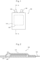
- the non-aqueous secondary batteries according to the first, second, and third embodiments of the present invention are secondary batteries comprising a positive electrode, a negative electrode, and a non-aqueous electrolyte solution, for example, may be lithium-ion batteries, and more specifically, may be lithium-ion batteries as shown schematically in the plan view in FIG. 1 and in the cross-sectional view in FIG. 2 .
- separator 170 comprises a separator 170; a positive electrode 150 and a negative electrode 160 interposing the separator 170 from both sides; further interposing a laminated body thereof (separator 170, positive electrode 150, and negative electrode 160), a positive electrode lead body 130 (connected to positive electrode 150) and a negative electrode lead body 140 (connected to negative electrode 160); and housing these components a battery outer packaging 110.
- a laminated body in which the positive electrode 150, the separator 170, and the negative electrode 160 are layered is impregnated with the non-aqueous electrolyte solution according to the first, second, and third embodiments.
- the first embodiment of the present invention will be described in detail below.
- a non-aqueous electrolyte solution for a non-aqueous lithium-ion secondary battery and a non-aqueous lithium-ion battery comprising the same are provided.
- the non-aqueous lithium-ion secondary battery according to the first embodiment may comprise, but is not limited to, the configuration of the lithium-ion battery 100 shown in FIGS. 1 and 2 .
- non-aqueous electrolyte solution in the first embodiment refers to a non-aqueous electrolyte solution that is 1% by mass or less of water based on the total amount of the non-aqueous electrolyte solution and contains a non-aqueous solvent and a lithium salt.
- the non-aqueous electrolyte solution according to the first embodiment preferably contains as little water as possible.
- the electrolyte solution may contain a very small amount of water as long as achieving the objects of the present invention is not hindered.
- Such water content as an amount per total amount of the non-aqueous electrolyte solution, is 300 mass ppm or less, and preferably 200 mass ppm or less.
- constituent materials of known non-aqueous electrolyte solutions used in lithium-ion batteries can be appropriately selected and applied as additional components.
- non-aqueous solvent in the first embodiment refers to an element except the lithium salt and various additives from the non-aqueous electrolyte solution.
- the non-aqueous electrolyte solution in the first embodiment comprises an electrode-protecting additive
- the “non-aqueous solvent” refers to an element except the lithium salt and additives other than the electrode-protecting additive from the non-aqueous electrolyte solution.
- non-aqueous solvents include alcohols such as methanol and ethanol; and aprotic solvents. Among these, an aprotic solvent is preferable as the non-aqueous solvent.
- the non-aqueous solvent may contain a solvent other than an aprotic solvent as long as achieving the objects of the present invention is not hindered.
- the non-aqueous solvent according to the non-aqueous electrolyte solution of the first embodiment contains acetonitrile as an aprotic solvent. Since the ion-conducting properties of the non-aqueous electrolyte solution is improved by the non-aqueous solvent containing acetonitrile, diffusivity of lithium ions within the battery can be increased. Therefore, when the non-aqueous electrolyte solution contains acetonitrile, particularly even in a positive electrode in which the positive electrode active material layer is thickened to increase the filling amount of positive electrode active material, lithium ions can satisfactory diffuse into regions near the current collector that are difficult for lithium ions to reach during discharge at high load. Sufficient capacity can thereby be drawn out even during high-load discharge, and a non-aqueous secondary battery having excellent load characteristics can be obtained.
- the rapid charging characteristics of the non-aqueous secondary battery can be enhanced.
- the capacity per unit time during CC charging period is larger than the charge capacity per unit time during CV charging period.
- acetonitrile is used in the non-aqueous solvent of the non-aqueous electrolyte solution, in addition to increasing the region where CC charging can be carried out (lengthening CC charging time), since charging current can also be increased, the time from the start of charging to a fully charged state of the non-aqueous secondary battery can be significantly shortened.
- Acetonitrile easily undergoes electrochemically reductive decomposition. Therefore, when acetonitrile is used, it is preferable that another solvent (for example, aprotic solvent other than acetonitrile) be used in combination with acetonitrile as the non-aqueous solvent and/or an electrode-protecting additive for forming a protective film on the electrode be added.
- aprotic solvent other than acetonitrile for example, aprotic solvent other than acetonitrile
- a negative electrode protective film derived from vinylene carbonate has high resistance, and tends to lead to a decrease in performance during rapid charging and in low-temperature environment and battery swelling due to gas generation during decomposition.
- Ethylene sulfite has a lower lowest unoccupied molecular orbital (LUMO) level than other oxygen- and sulfur-containing compounds, can be reductively decomposed at a lower potential than vinylene carbonate to form a negative electrode protective film, and can decrease the addition amount of vinylene carbonate to solve the problem from a negative electrode protective film derived from vinylene carbonate.
- LUMO lowest unoccupied molecular orbital
- a negative electrode protective film derived from ethylene sulfite has low resistance in a wide temperature range, and promotes the formation of a negative electrode SEI (solid electrolyte interface) that is highly durable against acetonitrile and decomposition products thereof, whereby a non-aqueous electrolyte solution and a non-aqueous secondary battery capable of operating stably at high current density can be provided.
- a negative electrode SEI solid electrolyte interface
- the total content of vinylene carbonate and ethylene sulfite in the non-aqueous electrolyte solution of the first embodiment is preferably 0.1% by volume or greater and less than 15% by volume relative to the total amount of the non-aqueous solvent, from the viewpoint of suppressing an increase in internal resistance.
- the content of ethylene sulfite is preferably 0.1% by volume or greater and less than 6% by volume, and even more preferably 1% by volume or greater and less than 5% by volume relative to the total amount of the non-aqueous solvent.
- cyclic carbonates can include ethylene carbonate, propylene carbonate, 1,2-butylene carbonate, trans-2,3-butylene carbonate, cis-2,3-butylene carbonate, 1,2-pentylene carbonate, trans-2,3-pentylene carbonate, cis-2,3-pentylene carbonate, vinylene carbonate (VC), 4,5-dimethylvinylene carbonate, and vinyl ethylene carbonate.
- VC vinylene carbonate
- fluoroethylene carbonates can include 4-fluoro-1,3-dioxolan-2-one, 4,4-difluoro-1,3-dioxolan-2-one, cis-4,5-difluoro-1,3-dioxolan-2-one, trans-4,5-difluoro-1,3-dioxolan-2-one, 4,4,5-trifluoro-1,3-dioxolan-2-one, 4,4,5,5-tetrafluoro-1,3-dioxolan-2-one, and 4,4,5-trifluoro-5-methyl-1,3-dioxolan-2-one.
- lactones can include ⁇ -butyrolactone, ⁇ -methyl- ⁇ -butyrolactone, ⁇ -valerolactone, ⁇ -caprolactone, ⁇ -valerolactone, ⁇ -caprolactone, and ⁇ -caprolactone.
- organic compounds comprising a sulfur atom can include ethylene sulfite, propylene sulfite, butylene sulfite, pentene sulfite, sulfolane, 3-sulfolane, 3-methylsulfolane, 1,3-propanesultone, 1,4-butanesultone, 1-propene 1,3-sultone, dimethylsulfoxide, tetramethylene sulfoxide, and ethylene glycol sulfite.
- chain carbonates can include ethylene methyl carbonate, dimethyl carbonate, diethyl carbonate, methyl propyl carbonate, methyl isopropyl carbonate, dipropyl carbonate, methyl butyl carbonate, dibutyl carbonate, ethyl propyl carbonate, and diisobutyl carbonate.
- cyclic ethers can include tetrahydrofuran, 2-methyl tetrahydrofuran, 1,4-dioxane, and 1,3-dioxane.
- Examples of mononitriles other than acetonitrile can include propionitrile, butyronitrile, valeronitrile, benzonitrile, and acrylonitrile.
- alkoxy-substituted nitriles can include methoxyacetonitrile and 3-methoxypropionitrile.
- dinitriles include malononitrile, succinonitrile, glutaronitrile, adiponitrile, 1,4-dicyanoheptane, 1,5-dicyanopentane, 1,6-dicyanohexane, 1,7-dicyanoheptane, 2,6-dicyanoheptane, 1,8-dicyanooctane, 2,7-dicyanooctane, 1,9-dicyanononane, 2,8-dicyanononane, 1,10-dicyanodecane, 1,6-dicyanodecane, and 2,4-dimethylglutaronitrile.
- Examples of cyclic nitriles can include benzonitrile.
- Examples of short chain fatty acid esters can include methyl acetate, methyl propionate, methyl isobutyrate, methyl butyrate, methyl isovalerate, methyl valerate, methyl pivalate, methyl hydroangelate, methyl caproate, ethyl acetate, ethyl propionate, ethyl isobutyrate, ethyl butyrate, ethyl isovalerate, ethyl valerate, ethyl pivalate, ethyl hydroangelate, ethyl caproate, propyl acetate, propyl propionate, propyl isobutyrate, propyl butyrate, propyl isovalerate, propyl valerate, propyl pivalate, propyl hydroangelate, propyl caproate, isopropyl acetate, isopropyl propionate, isopropyl isobutyrate, isopropyl buty
- chain ethers can include dimethoxyethane, diethyl ether, 1,3-dioxolane, diglyme, triglyme, and tetraglyme.
- fluorinated ethers can include Rf 20 -OR 21 (wherein Rf 20 represents an alkyl group containing a fluorine atom, and R 7 represents a monovalent organic group optionally containing a fluorine atom).
- ketones can include acetone, methyl ethyl ketone, and methyl isobutyl ketone.
- Examples of compounds in which some or all of the H atoms of the aprotic solvent are substituted with halogen atoms can include compounds in which the halogen atoms are fluorine.
- fluorides of chain carbonates include methyl trifluoroethyl carbonate, trifluorodimethyl carbonate, trifluorodiethyl carbonate, trifluoroethyl methyl carbonate, methyl 2,2-difluoroethyl carbonate, methyl 2,2,2-trifluoroethyl carbonate, and methyl 2,2,3,3-tetrafluoropropyl carbonate.
- the above fluorinated chain carbonate can be represented by the following general formula: R 1 -O-C(O)O-R 2 wherein R 1 and R 2 are at least one selected from the group consisting of CH 3 , CH 2 CH 3 , CH 2 CH 2 CH 3 , CH(CH 3 ) 2 , and CH 2 Rf 3 ; Rf 3 is an alkyl group having 1 to 3 carbon atoms in which hydrogen atoms are substituted with at least one fluorine atom; and R 1 and/or R 2 contains at least one fluorine atom.
- fluorides of short chain fatty acid esters include fluorinated short chain fatty acid esters typified by 2,2-difluoroethyl acetate, 2,2,2-trifluoroethyl acetate, and 2,2,3,3-tetrafluoropropyl acetate.
- the fluorinated short chain fatty acid ester can be represented by the following general formula: R 10 -C(O)O-R 11 wherein R 10 is at least one selected from the group consisting of CH 3 , CH 2 CH 3 , CH 2 CH 2 CH 3 , CH(CH 3 ) 2 , CF 3 CF 2 H, CFH 2 , CF 2 Rf 12 , CFHRf 12 , and CH 2 Rf 13 ; R 11 is at least one selected from the group consisting of CH 3 , CH 2 CH 3 , CH 2 CH 2 CH 3 , CH(CH 3 ) 2 , and CH 2 Rf 13 .
- Rf 12 is an alkyl group having 1 to 3 carbon atoms in which hydrogen atoms may be substituted with at least one fluorine atom
- Rf 13 is an alkyl group having 1 to 3 carbon atoms in which hydrogen atoms are substituted with at least one fluorine atom
- R 10 and/or R 11 contains at least one fluorine atom
- R 11 is not CH 3 when R 10 is CF 2 H.
- the aprotic solvent other than acetonitrile in the first embodiment can be used alone, or may be used in combination of two or more.
- the non-aqueous solvent in the first embodiment it is preferable that one or more of a cyclic carbonate and a chain carbonate be used in combination with acetonitrile, from the viewpoint of improving stability of the non-aqueous electrolyte solution. From this point of view, for the non-aqueous electrolyte solvent in the first embodiment, it is more preferable that a cyclic carbonate be used in combination with acetonitrile, and it is even more preferable that both of a cyclic carbonate and a chain carbonate be used in combination with acetonitrile.
- cyclic carbonate other than vinylene carbonate (VC) is used with acetonitrile
- the cyclic carbonate comprise ethylene carbonate and/or fluoroethylene carbonate.
- the non-aqueous electrolyte solution of the first embodiment is for use in lithium-ion secondary batteries, needs only to comprise a lithium salt as an electrolyte salt, and is not particularly limited regarding additional electrolyte salts.
- a lithium salt as an electrolyte salt
- additional electrolyte salts for example, in the first embodiment, LiPF 6 and a lithium-containing imide salt may be contained as the lithium salt.
- the lithium-containing imide salt is a lithium salt represented by LiN(SO 2 CmF 2m+1 ) 2 (wherein m is an integer of 0 to 8), and specifically, at least one of LiN(SO 2 F) 2 and LiN(SO 2 CF 3 ) 2 is preferably included therein. Only one or both of these imide salts may be contained, or an imide salt other than these imide salts may be contained.
- a lithium-containing imide salt be contained at a molar concentration where LiPF 6 ⁇ lithium-containing imide salt, so that association and precipitation of the lithium salt and acetonitrile can be suppressed at low temperature.
- the content of the lithium-containing imide salt be 0.5 mol or more and 3 mol or less relative to 1 L of non-aqueous solvent, from the viewpoint of ion supply amount.
- acetonitrile-containing non-aqueous electrolyte solution comprising at least one of LiN(SO 2 F) 2 and LiN(SO 2 CF 3 ) 2
- a decrease in ionic conductivity in a low-temperature region such as -10°C or -30°C can be effectively suppressed, and excellent low-temperature characteristics can be obtained.
- an increase in resistance during high-temperature heating can also be more effectively suppressed.
- a fluorine-containing inorganic lithium salt other than LiPF 6 may further be contained.
- a fluorine-containing inorganic lithium salt such as LiBF 4 , LiAsF 6 , Li 2 SiF 6 , LiSbF 6 , Li 2 B 12 F b H 12-b (wherein b is an integer of 0 to 3) may be contained.
- the "inorganic lithium salt” in the first embodiment refers to a lithium salt comprising no carbon atom in the anion and soluble in acetonitrile.
- fluorine-containing inorganic lithium salt compounds that are double salts of LiF and a Lewis acid are desirable, and among these, fluorine-containing inorganic salts comprising a phosphorus atom are more preferably used since the release of free fluorine atoms is facilitated.
- a typical fluorine-containing inorganic lithium salt is LiPF 6 , which releases a PF 6 anion when dissolved.
- a fluorine-containing inorganic lithium salt comprising a boron atom when used as the fluorine-containing inorganic lithium salt, facilitates trapping of excess free acid components that may cause battery deterioration, and is thus preferable. From this viewpoint, LiBF 4 is particularly preferable.
- the content of the fluorine-containing inorganic lithium salt in the non-aqueous electrolyte solution of the first embodiment is not particularly limited, but is preferably 0.01 mol or more, more preferably 0.02 mol or more, and even more preferably 0.03 mol or more relative to 1 L of non-aqueous solvent.
- the content of the fluorine-containing inorganic lithium salt is preferably less than 1.5 mol, more preferably less than 0.5 mol, and even more preferably less than 0.1 mol relative to 1 L of non-aqueous solvent.
- the content of the fluorine-containing inorganic lithium salt is within the above range of less than 1.5 mol, there is a tendency that ionic conductivity is increased, high-output characteristics can be exhibited, and a decrease in ionic conductivity due to an increase in viscosity at low temperatures can be suppressed, and there is a tendency that high-temperature cycle characteristics and other battery characteristics of the non-aqueous secondary battery can be further improved while maintaining excellent performance of the non-aqueous electrolyte solution.
- the non-aqueous electrolyte solution of the first embodiment may further comprise an organic lithium salt.
- organic lithium salt in the first embodiment refers to a lithium salt comprising a carbon atom in the anion and soluble in acetonitrile.
- organic lithium salts can include organic lithium salts having an oxalate group.
- organic lithium salts having an oxalate group include organic lithium salts represented by each of LiB(C 2 O 4 ) 2 , LiBF 2 (C 2 O 4 ), LiPF 4 (C 2 O 4 ), and LiPF 2 (C 2 O 4 ) 2 .
- at least one lithium salt selected from lithium salts represented by LiB(C 2 O 4 ) 2 and LiBF 2 (C 2 O 4 ) is preferable. It is more preferable that one or more of these lithium salts be used together with a fluorine-containing inorganic lithium salt.
- the organic lithium salt having an oxalate group may be contained in the negative electrode (negative electrode active material layer), in addition to being added to the non-aqueous electrolyte solution.
- the addition amount of the organic lithium salt having an oxalate group to the non-aqueous electrolyte solution is preferably 0.005 mol or more, more preferably 0.02 mol or more, and even more preferably 0.05 mol or more.
- an amount per L of non-aqueous solvent of the non-aqueous electrolyte solution is preferably 0.005 mol or more, more preferably 0.02 mol or more, and even more preferably 0.05 mol or more.
- the addition amount of the above organic lithium salt having an oxalate group to the non-aqueous electrolyte solution, in an amount per L of non-aqueous solvent of the non-aqueous electrolyte solution, is preferably less than 1.0 mol, more preferably less than 0.5 mol, and even more preferably less than 0.2 mol.
- organic lithium salts having an oxalate group are poorly soluble in low-polarity organic solvents, particularly chain carbonates.
- the organic lithium salt having an oxalate group may contain a trace amount of lithium oxalate, and when mixed as a non-aqueous electrolyte solution, may react with a trace amount of water contained in another raw material to newly generate a white precipitate of lithium oxalate. Therefore, the content of lithium oxalate in the non-aqueous electrolyte solution of the first embodiment, although not particularly limited, is preferably 0 to 500 ppm.
- a lithium salt generally used for non-aqueous secondary batteries may be supplementally added as the lithium salt in the first embodiment.
- additional lithium salts include inorganic lithium salts not containing a fluorine atom in the anion, such as LiClO 4 , LiAlO 4 , LiAlCl 4 , LiB 10 Cl 10 , and Li chloroborane; organic lithium salts such as LiCF 3 SO 3 , LiCF 3 CO 2 , Li 2 C 2 F 4 (SO 3 ) 2 , LiC(CF 3 SO 2 ) 3 , LiC n F (2n+1) SO 3 (wherein n ⁇ 2), lower aliphatic carboxylic acid Li, Li tetraphenylborate, and LiB(C 3 O 4 H 2 ) 2 ; organic lithium salts represented by LiPF n (C p F 2p+1 ) 6-n , such as LiPF 5 (CF 3 ) (wherein n is an integer of 1 to 5 and p
- the non-aqueous electrolyte solution according to the first embodiment can comprise an additive other than the non-aqueous solvent and electrolyte salt described above.
- the non-aqueous electrolyte solution of the first embodiment comprises vinylene carbonate (VC).
- Vinylene carbonate (VC) causes a reduction reaction on the negative electrode active material surface to form a film, and thus requires an addition amount corresponding to the mass of the negative electrode.
- VC vinylene carbonate
- the content of vinylene carbonate (VC) in the non-aqueous electrode solution is 7 ⁇ A/X% by mass or greater.
- the VC content is preferably 10 ⁇ A/X% by mass or greater, and more preferably 15 ⁇ A/X% by mass or greater.
- capacity efficiency is improved over a long period of time even in high-temperature environment, charge capacity and discharge capacity are stabilized even in a non-aqueous electrolyte solution comprising acetonitrile.
- the addition of an excessive amount of vinylene carbonate (VC) may decrease the viscosity of the non-aqueous electrolyte solution, degrade the low-temperature characteristics thereof, and generate excessive gas.
- the addition amount of vinylene carbonate (VC) is preferably 10% by mass or less, more preferably 9% by mass or less, even more preferably 8% by mass or less, and particularly preferably 7% by mass or less relative to the mass of the non-aqueous electrolyte solution.
- VC vinylene carbonate
- X is preferably 50 or greater and 2000 or less, and/or A is preferably 5 or greater and 70 or less.
- X of the non-aqueous lithium-ion secondary battery containing X% by mass of the non-aqueous electrolyte solution of the first embodiment is more preferably 200 or less, and even more preferably 98 or less relative to the mass of the negative electrode excluding the negative electrode current collector.
- the content of the non-aqueous electrolyte solution relative to the mass of the negative electrode excluding the negative electrode current collector is less than a certain value, impregnation into an electrode or separator may be insufficient.
- X of the non-aqueous lithium-ion secondary battery containing the non-aqueous electrolyte solution of the first embodiment is more preferably 55 or greater, even more preferably 60 or greater, and particularly preferably 65 or greater.
- A when the content of acetonitrile relative to the non-aqueous solvent is expressed as A% by volume, containing acetonitrile in the non-aqueous electrolyte solution is expected to improve the output performance. From this viewpoint, A is more preferably 8 or greater, and even more preferably 16 or greater.
- A is more preferably 60 or less, and even more preferably 35 or less.
- the non-aqueous electrolyte solution of the first embodiment preferably comprises one or both of sulfate ions and sulfite ions. It is considered that sulfate ions can prevent metal impurities from depositing on the negative electrode and damaging the SEI by binding to the metal impurities.
- the lower limit of the addition amount of sulfate ions is not particularly determined, but is preferably at a concentration of the metal impurities of the electrolyte solution material or higher. When metal elution from the electrode is taken into consideration, the lower limit is preferably 1 ppm or more, and more preferably 10 ppm or more relative to the mass of the non-aqueous electrolyte solution.
- the content of sulfate ions is preferably 7 ⁇ A/X% by mass or less or less than 7 ⁇ A/X% by mass relative to the mass of the non-aqueous electrolyte solution, and is preferably 10% by mass or less, more preferably 8% by mass or less, and particularly preferably 5% by mass or less relative to the mass of vinylene carbonate (VC).
- the non-aqueous electrolyte solution of the first embodiment may comprise sulfite ions, which are expected to bind with metal elution components and prevent damage to the SEI.
- the addition amount of sulfite ions is preferably 10% by mass or less, more preferably 8% by mass or less, and particularly preferably 5% by mass or less relative to the mass of vinylene carbonate (VC) in the non-aqueous electrolyte solution.
- the total content of sulfate ions and sulfite ions in the non-aqueous electrolyte solution is 1 ppm or more and 7 ⁇ A/X% by mass or less relative to the mass of the non-aqueous electrolyte solution, and is preferably 10% by mass or less of the content of VC in the non-aqueous electrolyte solution.
- the method of adding each ion to the non-aqueous electrolyte solution is not particularly limited, and needs only to be contained in the non-aqueous electrolyte solution by decomposing an organic compound in the non-aqueous electrolyte solution or adding a sulfate or sulfite.
- an inorganic salt for example, lithium sulfate or lithium sulfite is preferable since the addition thereof does not add metal impurities to the composition of the lithium-ion secondary battery non-aqueous electrolyte solution.
- An additional electrode-protecting additive is not particularly limited as long as achieving the object of the present invention is not hindered, and may substantially overlap with the substances acting as solvents for dissolving lithium salts (i.e., non-aqueous solvents described above) (however, acetonitrile, vinylene carbonate, and ethylene sulfite as an organic compound comprising a sulfur atom described above are excluded).
- the electrode-protecting additive is preferably a substance that contributes to performance improvement of the non-aqueous electrolyte solution and non-aqueous secondary battery of the first embodiment, but also encompasses substances not directly involved in the electrochemical reaction.
- additional electrode-protecting additives include fluoroethylene carbonates typified by 4-fluoro-1,3-dioxolan-2-one, 4,4-difluoro-1,3-dioxolan-2-one, cis-4,5-difluoro-1,3-dioxolan-2-one, trans-4,5-difluoro-1,3-dioxolan-2-one, 4,4,5-trifluoro-1,3-dioxolan-2-one, 4,4,5,5-tetrafluoro-1,3-dioxolan-2-one, and 4,4,5-trifluoro-5-methyl-1,3-dioxolan-2-one; unsaturated bond-containing cyclic carbonates such as 4,5-dimethylvinylene carbonate and vinyl ethylene carbonate; lactones typified by ⁇ -butyrolactone, ⁇ -valerolactone, ⁇ -caprolactone, ⁇ -valerolactone, ⁇
- the content of the electrode-protecting additive in the non-aqueous electrolyte solution of the first embodiment is not particularly limited, but is preferably 0.1 to 30% by volume, more preferably 0.3 to 15% by volume, and even more preferably 0.5 to 4% by volume as the content of the electrolyte-protecting additive relative to the entire amount of the non-aqueous solvent.
- the larger the content of the electrode-protecting additive the more the deterioration of the non-aqueous electrolyte solution is suppressed.
- the smaller the content of the electrode-protecting additive the more the high-output characteristics of the non-aqueous secondary battery in low-temperature environment are improved. Therefore, by adjusting the content of the electrode-protecting additive within the above range, there is a tendency that excellent performance based on high ionic conductivity of the non-aqueous electrolyte solution can be maximized without impairing the basic function of the non-aqueous secondary battery.
- the cycle performance, high-output performance in low-temperature environment, and other battery characteristics of the non-aqueous secondary battery can all be further improved.
- the content of the additionally optional additive in the first embodiment is calculated as a mass percentage relative to the total mass of all components constituting the non-aqueous electrolyte solution.
- the content of the additionally optional additive is not particularly limited, but is preferably in the range of 0.01% by mass or greater and 10% by mass or less, more preferably 0.02% by mass or greater and 5% by mass or less, and even more preferably 0.05% by mass or greater and 3% by mass or less relative to the total amount of the non-aqueous electrolyte solution.
- the positive electrode active material layer be arranged on one side or both sides of the positive electrode current collector, contain a positive electrode active material, and further contain a conductive aid and a binder as needed.
- the positive electrode active material layer preferably contains a material capable of occluding and releasing lithium ions as a positive electrode active material. It is preferable that such a material be used since there is a tendency that high voltage and high energy density can be obtained.
- the positive electrode active material contained in the positive electrode active material layer is suitably a metal phosphate compound comprising lithium and a transition metal element represented by the following general formula (1): Li W MPO 4 ⁇ (1)
- the positive electrode active material include Li compounds such as Li W FePO 4 , and lithium cobalt oxides typified by LiCoO 2 ; lithium manganese oxides typified by LiMnO 2 , LiMn 2 O 4 , and Li 2 Mn 2 O 4 ; lithium nickel oxides typified by LiNiO 2 ; and lithium-containing composite metal oxides represented by Li z MO 2 (wherein M includes at least one transition metal element selected from the group consisting of Ni, Mn, and Co and represents two or more metal elements selected from the group consisting of Ni, Mn, Co, Al, and Mg, and z represents a number greater than 0.9 and less than 1.2) typified by LiNi 1/3 Co 1/3 Mn 1/3 O 2 , LiNi 0.5 Co 0.2 Mn 0.3 O 2 , and LiNi 0.8 Co 0.2 O 2 .
- LiNi 1/3 Co 1/3 Mn 1/3 O 2 LiNi 0.5 Co 0.2 Mn 0.3 O 2
- LiNi 0.8 Co 0.2 O 2 Li
- the Ni content ratio q of the Li-containing metal oxide represented by the general formula (2) be 0.5 ⁇ q ⁇ 1.2, since a decrease in use amount of the rare metal Co and a high energy density are both achieved.
- positive electrode active materials include lithium-containing composite metal oxides typified by LiNi 0.6 Co 0.2 Mn 0.2 O 2 , LiNi 0.75 Co 0.15 Mn 0.15 O 2 , LiNi 0.8 Co 0.1 Mn 0.1 O 2 , LiNi 0.85 Co 0.075 Mn 0.075 O 2 , LiNi 0.8 Co 0.15 Al 0.05 O 2 , LiNi 0.81 Co 0.1 Al 0.09 O 2 , and LiNi 0.85 Co 0.1 Al 0.05 O 2 .
- Active sites that oxidize and deteriorate the non-aqueous electrolyte solution are intrinsic in the positive electrode active material of the Li-containing metal oxide represented by the general formula (2), and these active sites may unintentionally consume the compounds added to protect the negative electrode on the positive electrode side.
- acid anhydrides tend to be easily affected. Particularly, the effect of adding an acid anhydride is enormous when acetonitrile is contained as the non-aqueous solvent, and thus the consumption of the acid anhydride on the positive electrode side is a fatal problem.
- the decomposition products of these additives that are incorporated and deposited on the positive electrode side not only increase the internal resistance of the non-aqueous secondary battery, but also accelerate the deterioration of the lithium salt.
- the protection of the negative electrode surface, which was the original purpose, is also insufficient.
- the positive electrode active material contain at least one metal selected from the group consisting of Al, Sn, In, Fe, V, Cu, Mg, Ti, Zn, Mo, Zr, Sr, and Ba.
- the surface of the positive electrode active material is preferably coated with a compound containing at least one metal element selected from the group consisting of Zr, Ti, Al, and Nb. Further, the surface of the positive electrode active material is more preferably coated with an oxide containing at least one metal element selected from the group consisting of Zr, Ti, Al, and Nb. Furthermore, the surface of the positive electrode active material is particularly preferably coated with at least one oxide selected from the group consisting of ZrO 2 , TiO 2 , Al 2 O 3 , NbO 3 , and LiNbO 2 , since the permeation of lithium ions is not inhibited.
- the positive electrode active material may be a lithium-containing compound other than the Li-containing metal oxide represented by the formula (1) or (2), and is not particularly limited as long as lithium is contained.
- lithium-containing compounds include composite oxides comprising lithium and a transition metal element, metal chalcogenides comprising lithium, and metal silicate compounds comprising lithium and a transition metal element.
- the lithium-containing compound is preferably a metal phosphate compound comprising, in particular, lithium and at least one transition metal element selected from the group consisting of Co, Ni, Mn, Fe, Cu, Zn, Cr, V, and Ti.
- lithium-containing compounds include compounds represented by each the following formula (Xa): Li v M I D 2 ⁇ (Xa)
- the lithium-containing compounds represented by the above formula (Xa) have a layered structure, and the compounds represented by the formula (1) and the above formula (Xb) have an olivine structure.
- These lithium-containing compounds may be compounds in which a portion of the transition metal element is substituted with Al, Mg, or another transition metal element, compounds in which such a metal element is contained in the crystal grain boundaries, compounds in which a portion of oxygen atoms is substituted with fluorine atoms, or compounds in which at least a portion of the positive electrode active material surface is coated with another positive electrode active material, for the purpose of stabilizing the structure.
- a lithium-containing compound as described above may be used, or the lithium-containing compound may be used in combination with an additional positive electrode active material.
- additional positive electrode active materials include metal oxides and metal chalcogenides having a tunnel structure and a layered structure; sulfur; and conductive polymers.
- metal oxides and metal chalcogenides having a tunnel structure and a layered structure include oxides, sulfides, and selenides of metals other than lithium, such as MnO 2 , FeO 2 , FeS 2 , V 2 O 5 , V 6 O 13 , TiO 2 , TiS 2 , MoS 2 , and NbSe 2 .
- conductive polymers include conductive polymers typified by polyaniline, polythiophene, polyacetylene, and polypyrrole.
- the additional positive electrode active material described above is used alone or in combination of two or more, and is not particularly limited. However, it is preferable that the positive electrode active material layer contain at least one transition metal element selected from Ni, Mn, and Co, since lithium ions can be reversibly and stably occluded and released and high energy density can be achieved.
- the use ratio of the two components is preferably 80% by mass or greater, and more preferably 85% by mass or greater.
- Examples of conductive aid include graphite; carbon black typified by acetylene black and Ketjen black; and carbon fiber.
- the content ratio of the conductive aid is preferably 10 parts by mass or less, and more preferably 1 to 5 parts by mass relative to 100 parts by mass of the positive electrode active material.
- binders examples include polyvinylidene fluoride (PVDF), polytetrafluoroethylene (PTFE), polyacrylic acid, styrene-butadiene rubber, and fluororubber.
- PVDF polyvinylidene fluoride
- PTFE polytetrafluoroethylene
- the content ratio of the binder is preferably 10 parts by mass or less, and more preferably 0.5 to 8 parts by mass relative to 100 parts by mass of the positive electrode active material.
- the positive electrode active material layer is formed by applying a positive electrode mixture-containing slurry in which a positive electrode mixture comprising a positive electrode active material, mixed with a conductive aid and a binder as needed, is dispersed in a solvent to a positive electrode current collector and drying (removing solvent), and pressing as needed.
- a solvent is not particularly limited, and any conventionally known solvent can be used. Examples include N-methyl-2-pyrrolidone, dimethylformamide, dimethylacetoamide, and water.
- the positive electrode current collector for example, is composed of a metal foil such as an aluminum foil, a nickel foil, or a stainless-steel foil.
- the positive electrode current collector may be subjected to carbon coating on the surface, or may be processed into a mesh form.
- the thickness of the positive electrode current collector is preferably 5 to 40 ⁇ m, more preferably 7 to 35 ⁇ m, and even more preferably 9 to 30 ⁇ m.
- the negative electrode 160 shown in FIGS. 1 and 2 is composed of a negative electrode active material, a conductive aid and a binder, as needed, and a negative electrode current collector.
- the negative electrode 160 can act as a negative electrode of a non-aqueous secondary battery.
- the negative electrode active material layer is arranged on one side or both sides of the negative electrode current collector, contains a negative electrode active material, and preferably contains a conductive aid and a binder, as needed.
- the non-aqueous lithium-ion secondary battery according to the first embodiment, as described above, preferably has a structure capable of containing X% by mass of the non-aqueous electrolyte solution relative to the mass of the negative electrode excluding the negative electrode current collector.
- negative electrode active materials include, in addition to carbon materials typified by amorphous carbon (hard carbon), graphite (for example, artificial graphite and natural graphite), pyrolytic carbon, coke, glassy carbon, baked bodies of organic polymer compounds, mesocarbon microbeads, carbon fiber, activated carbon, carbon colloids, and carbon black, metallic lithium, metal oxides, metal nitrides, lithium alloys, tin alloys, silicon alloys, intermetallic compounds, organic compounds, inorganic compounds, metal complexes, and organic polymer compounds.
- the negative electrode active material is used alone or in combination of two or more.
- the negative electrode active material from the viewpoint of application of the non-aqueous electrolyte solution according to the first embodiment, is preferably graphite.
- the negative electrode active material layer preferably contains a material, as the negative electrode active material, capable of absorbing lithium ions at a potential lower than 0.4 V vs. Li/Li + .
- Examples of conductive aids include graphite; carbon black typified by acetylene black and Ketjen black; and carbon fiber.
- the content ratio of the conductive aid is preferably 20 parts by mass or less, and more preferably 0.1 to 10 parts by mass relative to 100 parts by mass of the negative electrode active material.
- binders include carboxymethyl cellulose, PVDF, PTFE, polyacrylic acid, and fluororubber, and also include diene-based rubbers such as styrene-butadiene rubber.
- the content ratio of the binder is preferably 10 parts by mass or less, and more preferably 0.5 to 8 parts by mass relative to 100 parts by mass of the negative electrode active material.
- the negative electrode active material layer is formed by applying a negative electrode mixture-containing slurry in which a negative electrode mixture comprising a negative electrode active material, mixed with a conductive aid and a binder as needed, is dispersed in a solvent to a negative electrode current collector and drying (removing solvent), and pressing as needed.
- a solvent is not particularly limited, and any conventionally known solvent can be used. Examples include N-methyl-2-pyrrolidone, dimethylformamide, dimethylacetoamide, and water.
- the negative electrode current collector for example, is composed of a metal foil such as a copper foil, a nickel foil, or a stainless-steel foil.
- the negative electrode current collector may be subjected to carbon coating on the surface, or may be processed into a mesh form.
- the thickness of the negative electrode current collector is preferably 5 to 40 ⁇ m, more preferably 6 to 35 ⁇ m, and even more preferably 7 to 30 ⁇ m.
- the non-aqueous secondary battery 100 of the first embodiment preferably comprises a separator 170 between the positive electrode 150 and the negative electrode 160.
- the separator 170 may be, but is not limited to, the same ones that known non-aqueous secondary batteries comprise, has a large ion permeability, and is preferably a thin film having insulating properties and excellent mechanical strength.
- Examples of the separator 170 include woven fabrics, nonwoven fabrics, and synthetic resin microporous films. Among these, synthetic resin microporous films are preferable.
- polyolefin-based microporous films such as microporous films containing polyethylene or polypropylene as the main component or microporous films containing both of these polyolefins are suitably used.
- nonwoven fabrics include porous films made of heat-resistant resins such as glass, ceramic, polyolefin, polyester, polyamide, liquid crystal polyester, and aramid.
- the separator 170 may be in a configuration having one type of microporous film in a single layer or laminated in a plurality of layers, or may be in a configuration having two or more types of microporous films laminated.
- the separator 170 may be configured to have a single layer or a plurality of layers laminated using a mixed resin material obtained by melting and kneading two or more resin materials.
- inorganic particles may be present on the surface of or inside the separator, and an additional organic layer may be further applied or layered thereon.
- a crosslinked structure may be included. In order to enhance safety performance of the non-aqueous secondary battery, these methods may be combined as needed.
- the thickness of a microporous film that can be used as a separator is not particularly limited, and is preferably 1 ⁇ m or more from the viewpoint of film strength, and is preferably 500 ⁇ m or less from the viewpoint of permeability.
- the thickness of the microporous film from the viewpoint of being used in high-output applications such as safety tests, where the calorific value is relatively high and self-discharge characteristics better than those in the prior art are required, and from the viewpoint of windability with a large battery winding machine, is preferably 5 ⁇ m or more and 30 ⁇ m or less, and more preferably 10 ⁇ m or more and 25 ⁇ m or less.
- the thickness of the microporous film when short-circuit resistance performance and output performance are both emphasized, is even more preferably 15 ⁇ m or more and 25 ⁇ m or less, but when high energy density and output performance are both emphasized, is even more preferably 10 ⁇ m or more and less than 15 ⁇ m.
- the porosity of a microporous film that can be used as a separator is preferably 30% or greater and 90% or less, more preferably 35% or greater and 80% or less, and even more preferably 40% or greater and 70% or less.
- the porosity of the microporous film when the improvement of output performance is considered a priority while ensuring safety, is particularly preferably 50% or greater and 70% or less, and when short-circuit resistance performance and output performance are both emphasized, is particularly preferably 40% or greater and less than 50%.
- the air permeability of a microporous film that can be used as a separator is preferably 1 s/100 cm 3 or more and 400 s/100 cm 3 or less, and is more preferably 100 s/100 cm 3 or more and 350 s/100 cm 3 or less.
- the air permeability of the microporous film when short-circuit resistance performance and output performance are both emphasized, is particularly preferably 150 s/100 cm 3 or more and 350 s/100 cm 3 or less, and when the improvement of output performance is considered a priority while ensuring safety, is particularly preferably 100 s/100 cm 3 or more and less than 150 s/100 cm 3 .
- the ionic conductivity of the non-aqueous electrolyte solution is preferably 10 mS/cm or more, more preferably 15 mS/cm or more, and even more preferably 20 mS/cm or more.
- the film thickness, air permeability and porosity of the separator and the ionic conductivity of the non-aqueous electrolyte solution are not limited to the above examples.
- the configuration of the battery outer packaging 110 of the non-aqueous secondary battery 100 is not particularly limited.
- a battery can or a laminate film outer packaging can be used.
- the battery can for example, a metal can, such as square-type, prism-type, cylinder-type, oval-type, flat-type, coin-type, or button-type, composed of steel, stainless steel, aluminum, or clad material can be used.
- the laminate film outer packaging for example, a laminate film composed of a three-layer configuration of hot melt resin/metal film/resin can be used.
- the laminate film outer packaging can be used as an outer packaging by stacking two sheets with the hot melt resin side facing inward or by folding one so that the hot melt resin side faces inward and then sealing the edge portions with heat sealing.
- a positive electrode lead body 130 (or a positive electrode terminal and a lead tab connected to the positive electrode terminal) may be connected to the positive electrode current collector
- a negative electrode lead body 140 (or a negative electrode terminal and a lead tab connected to the negative electrode terminal) may be connected to the negative electrode current collector.
- the laminate film outer packaging may be sealed with the edge portions of the positive electrode lead body 130 and the negative electrode lead body 140 (or lead tabs connected to the positive electrode terminal and the negative electrode terminal, respectively) pulled to the outside of the outer packaging.
- the non-aqueous secondary battery 100 of the first embodiment may be produced by a known method, using the above non-aqueous electrolyte solution, and for example, a positive electrode 150 having a positive electrode active material layer on one side or both sides of a current collector, a negative electrode 160 having a negative electrode active material layer on one side or both sides of a current collector, a battery outer packaging 110, and if necessary, a separator 170.
- a laminated body consisting of a positive electrode 150, a negative electrode 160, and if necessary, a separator 170 is first formed.
- the laminated body can be, for example:
- the above laminated body is then housed within a battery outer packaging 110 (battery case), and the non-aqueous electrolyte solution according to the first embodiment is sealed inside the battery case, whereby a non-aqueous secondary battery of the first embodiment may be produced.
- battery outer packaging 110 battery case
- the non-aqueous electrolyte solution according to the first embodiment is sealed inside the battery case, whereby a non-aqueous secondary battery of the first embodiment may be produced.
- an electrolyte film in gel form can be produced in advance by impregnating a substrate consisting of a polymer material with the non-aqueous electrolyte solution, and a laminated body having a layered structure is formed using a positive electrode 150, a negative electrode 160, the electrolyte film, each in sheet form, and if necessary, a separator 170 and then housed within a battery outer packaging 110 to produce a non-aqueous secondary battery 100.
- the positions of the electrodes be fixed in advance with tape such as polyimide tape, polyphenylene sulfide tape, or polypropylene (PP) tape or adhesive when using the electrode structures in the non-aqueous secondary battery.
- the non-aqueous electrolyte solution using acetonitrile when used, due to the high ion-conducting properties thereof, there is a possibility that lithium ions released from the positive electrode during the initial charge of the non-aqueous secondary battery disperse to the entire negative electrode.
- the negative electrode active material layer In non-aqueous secondary batteries, the negative electrode active material layer generally has a larger area than the positive electrode active material layer.
- the lithium ions when lithium ions are diffused and occluded to a location of the negative electrode active material layer not facing the positive electrode active material layer, the lithium ions remain in the negative electrode without being released during the initial discharge. Therefore, the contributing portion of unreleased lithium ions becomes irreversible capacity. For this reason, a non-aqueous secondary battery using a non-aqueous electrolyte solution containing acetonitrile may have low initial charge-discharge efficiency.
- the concentration of current in the edge portions of the negative electrode active material layer during charging easily occurs, and lithium dendrites are easily generated.
- the ratio of the area of the entire negative electrode active material layer to the area of the portion where the positive electrode active material layer and the negative electrode active material layer face each other is not particularly limited, but is preferably greater than 1.0 and less than 1.1, more preferably greater than 1.002 and less than 1.09, even more preferably greater than 1.005 and less than 1.08, and particularly preferably greater than 1.01 and less than 1.08.
- a non-aqueous secondary battery using a non-aqueous electrolyte solution comprising acetonitrile by decreasing the ratio of the area of the entire negative electrode active material layer to the area of the portion where the positive electrode active material layer and the negative electrode active material layer face each other, the initial charge-discharge efficiency can be improved.
- the non-aqueous secondary battery 100 of the first embodiment can function as a battery upon the initial charge, and is stabilized by partially decomposing the non-aqueous electrolyte solution during the initial charge.
- the method of the initial charge is not particularly limited. However, the initial charge is preferably carried out at 0.001 to 0.3 C, more preferably 0.002 to 0.25 C, and even more preferably 0.003 to 0.2 C. The initial charge is also preferably carried out via constant voltage partway along charging.
- the capacity that can be stored by the negative electrode is preferably larger than the charge capacity that can be drawn from the positive electrode during charging, and lithium can be prevented from being deposited on the negative electrode.
- the charge capacity at an environmental temperature in the range of 23 of 30°C is preferably 70% or greater and 99% or less relative to the capacity of the negative electrode active material.
- the charge capacity at an environmental temperature in the range of 23 of 30°C is preferably 70% or greater and 99% or less relative to the capacity of the negative electrode active material.
- the non-aqueous secondary battery 100 of the first embodiment can also be used as a battery pack in which a plurality of non-aqueous secondary batteries 100 are connected in series or in parallel.
- the operating voltage range per battery is preferably 2 to 5 V.
- the non-aqueous secondary battery according to the second embodiment may comprise, but is not limited to, the configuration of the lithium-ion battery 100 shown in FIGS. 1 and 2 .
- the non-aqueous secondary battery according to the second embodiment comprises a negative electrode, a positive electrode, a separator, and a non-aqueous electrolyte solution.
- the non-aqueous secondary battery has been charged one or more times.
- the negative electrode comprises one or more of each of an inorganic lithium compound and an organic lithium compound that are extractable by immersing in an extraction solvent.
- the positive electrode preferably contains one or more positive electrode active materials capable of occluding and releasing lithium ions, and the negative electrode preferably contains a negative electrode active material comprising graphite.
- the non-aqueous electrolyte solution comprises acetonitrile as a non-aqueous solvent and a cyclic carbonate.
- the negative electrode preferably comprises a component that is extractable from the negative electrode by using water as the extraction solvent, and more preferably comprises at least one of the following (a) to (d):
- the component (a) can be classified as an inorganic lithium compound, and the components (b) and (d) can be classified as organic lithium compounds.
- the negative electrode according to the second embodiment from the viewpoint of prevention of reductive decomposition of acetonitrile, rapid stabilization of initial battery capacity, and efficiency of manufacturing process, preferably comprises the component (a) and at least one or all of the components (b) to (d).
- the above components are mainly generated on the negative electrode active material surface by reduction reaction of a cyclic carbonate, forming an SEI (solid electrolyte interface).
- the SEI forms a film that does not conduct electrons while conducting Li ions, and prevents other solvents from further reducing.
- the non-aqueous secondary battery of the second embodiment comprises acetonitrile as a non-aqueous solvent of the non-aqueous electrolyte solution. Since acetonitrile has low viscosity and high dielectric constant, and is easily coordinated to Li ions and moved to the vicinity of an electrode active material during charging and discharging, it is considered that due to these characteristics, the input-output characteristics are easily improved and stabilization of electrode capacity is quickly completed.
- the negative electrode film component in the second embodiment comprising acetonitrile preferably comprises the components (a) to (d), wherein the molar ratio of each of the components relative to the total amount of (a) to (d) (i.e., total content) is preferably 20 to 70 mol% for (a), 20 to 70 mol% for (b), 1 to 20 mol% for (c), and 1 to 20 mol% for (d), and more preferably 20 to 65 mol% for (a), 25 to 65 mol% for (b), 5 to 20 mol% for (c), and 5 to 20 mol% for (d).
- the negative electrode may contain PF 6 anions, and may also contain N(SO 2 F) 2 anions and/or N(SO 2 CF 3 ) 2 anions.
- the electrolyte solution may contain at least one anion selected from the group consisting of PF 6 anion, N(SO 2 CF 3 ) 2 anion, and N(SO 2 F) 2 anion.
- the above anion is preferable, from the viewpoint of promoting the effect of protective film formation and forming a non-conducting film on the surface of the surface foil acting as the positive electrode current collector, thereby suppressing an increase in internal resistance.
- the non-aqueous secondary battery of the second embodiment may be the non-aqueous secondary battery illustrated in FIGS. 1 and 2.
- FIG. 1 is a plan view schematically showing a non-aqueous secondary battery.
- FIG. 2 is a cross-sectional view along the A-A line.
- the non-aqueous secondary battery 100 shown in FIGS. 1 and 2 is configured as a pouch-type cell.
- a layered electrode structure formed by layering a positive electrode 150 and a negative electrode 160 via a separator 170 and a non-aqueous electrolyte solution (not illustrated) are housed within a space 120 of a battery outer packaging 110 composed of two aluminum laminate films.
- the battery outer packaging 110 is sealed at the outer periphery thereof by heat-fusing the upper and lower aluminum laminate films.
- a laminated body in which the positive electrode 150, the separator 170, and the negative electrode 160 are layered in order is impregnated with the non-aqueous electrolyte solution.
- the aluminum laminate film constituting the battery outer packaging 110 is preferably an aluminum foil coated on both sides with a polyolefin-based resin.
- the positive electrode 150 is connected to a positive electrode lead body 130 within the non-aqueous secondary battery 100.
- the negative electrode 160 is also connected to a negative electrode lead body 140 within the non-aqueous secondary battery 100.
- Each of the positive electrode lead body 130 and the negative electrode lead body 140 has one end pulled to the outside of the battery outer packaging 110 so as to be connectable to an external device. These ionomer portions are heat-fused with one side of the battery outer packaging 110.
- the non-aqueous secondary battery 100 illustrated in FIGS. 1 and 2 comprises a layered electrode structure having one positive electrode 150 and one negative electrode 160.
- the number of positive electrodes 150 and negative electrodes 160 layered can be appropriately increased according to capacity design.
- tabs of the same electrode may be joined by welding, and then joined to one lead body by welding, allowing the lead body to be extracted outside the battery.
- the above tabs of the same electrode can be formed from exposed portions of the current collector, or formed by welding metal pieces to the exposed portions of the current collector.
- the positive electrode 150 is composed of a positive electrode active material layer, prepared from a positive electrode mixture, and a positive electrode current collector.
- the negative electrode 160 is composed of a negative electrode active material layer, prepared from a negative electrode mixture, and a negative electrode current collector. The positive electrode 150 and negative electrode 160 are arranged so that the positive electrode active material layer and the negative electrode active material layer face each other via a separator 170.
- the non-aqueous electrolyte solution according to the second embodiment can have the configuration of the non-aqueous electrolyte solution according to the first embodiment indicated above.
- materials used for non-aqueous electrolyte solutions of conventional lithium-ion batteries can be applied to the non-aqueous electrolyte solution as long as the effect of the present invention is not impaired.
- non-aqueous electrolyte solution refers to an electrolyte solution containing a non-aqueous solvent and a lithium salt, wherein water is 1% by mass or less relative to the entire amount of the non-aqueous electrolyte solution.
- the ratio of water is 300 ppm or less, and more preferably, 200 ppm or less.
- the non-aqueous electrolyte solution may contain an additive.
- non-aqueous solvent in the second embodiment refers to an element except the lithium salt from the electrolyte solution.
- non-aqueous solvent refers to an element except the lithium salt and the additive from the electrolyte solution.
- the non-aqueous solvent in the second embodiment comprises acetonitrile as an indispensable component.
- the content of acetonitrile is preferably 1% by mass or greater and 60% by mass or less, more preferably 3% by mass or greater and 50% by mass or less, and even more preferably 5% by mass or greater and 40% by mass or less relative to the entire amount of the non-aqueous electrolyte solution.
- the non-aqueous solvent may comprise another non-aqueous solvent in addition to acetonitrile.
- non-aqueous solvents other than acetonitrile include alcohols such as methanol and ethanol; and aprotic solvents. Among these, aprotic polar solvents are preferable.
- aprotic solvents include cyclic carbonates typified by ethylene carbonate, propylene carbonate, 1,2-butylene carbonate, trans-2,3-butylene carbonate, cis-2,3-butylene carbonate, 1,2-pentylene carbonate, trans-2,3-pentylene carbonate, cis-2,3-pentylene carbonate, vinylene carbonate, 4,5-dimethylvinylene carbonate, and vinyl ethylene carbonate; fluoroethylene carbonates typified by 4-fluoro-1,3-dioxolan-2-one, 4,4-difluoro-1,3-dioxolan-2-one, cis-4,5-difluoro-1,3-dioxolan-2-one, trans-4,5-difluoro-1,3-dioxolan-2-one, 4,4,5-trifluoro-1,3-dioxolan-2-one, 4,4,5,
- the non-aqueous secondary battery of the second embodiment preferably comprises a cyclic carbonate in the non-aqueous electrolyte solution, and particularly preferably comprises ethylene carbonate and vinylene carbonate as the cyclic carbonate.
- Only one of the other cyclic and chain carbonates exemplified above may be selected and used, or two or more (for example, two or more of the cyclic carbonates exemplified above, two or more of the chain carbonates exemplified above, or two or more consisting of one or more of the cyclic carbonates exemplified above and one or more of the chain carbonates exemplified above) may be used.
- propylene carbonate or fluoroethylene carbonate is more preferable as the cyclic carbonate
- ethyl methyl carbonate, dimethyl carbonate, or diethyl carbonate is more preferable as the chain carbonate.
- Vinylene carbonate is highly reactive and is consumed according to the amount of negative electrode during the initial charge, promoting SEI formation.
- the SEI formation proceeds faster than acetonitrile undergoing reduction reaction on the negative electrode active material surface by sufficiently adding ethylene carbonate and vinylene carbonate before the initial charge of the battery so that a certain amount of ethylene carbonate and vinylene carbonate remains after SEI formation.
- Such rapid SEI formation reaction is considered to be achieved by competing reactions between ethylene carbonate and vinylene carbonate, and it is preferable that the two be contained in a predetermined ratio.
- the molar ratio of the remaining vinylene carbonate relative to ethylene carbonate contained in the non-aqueous electrolyte solution of the second embodiment after SEI formation reaction has progressed with the initial charge is preferably 0.01 to 30 mol%, more preferably 0.1 to 30 mol%, even more preferably 0.3 to 25 mol%, and particularly preferably 1 to 20 mol%.
- the non-aqueous secondary battery of the second embodiment comprises a suitable non-aqueous electrolyte solution before the initial charge.
- the content of vinylene carbonate is preferably 0.1% by mass or greater and 10% by mass or less relative to the entire amount of the non-aqueous electrolyte solution to maintain satisfactory reactivity.
- the addition amount as needed so that the initial charge and discharge are stable according to the content of the non-aqueous electrolyte solution in the battery, the content of acetonitrile, and the amount of negative electrode in the battery.
- the non-aqueous electrolyte solution sealed in the battery may have the configuration in the first embodiment.
- ethylene carbonate not only contributes to the formation of the SEI reaction but also acts as a suitable solvent for dissolving lithium salts, the content of ethylene carbonate is preferably 5% by mass or greater and 35% by mass or less, and more preferably 10% by mass or greater and 30% by mass or less relative to the total amount of the non-aqueous electrolyte solution.
- the lithium salt is not particularly limited as long as the effect of the present invention is not impaired.
- the lithium salt can include a fluorine-containing inorganic lithium salt and/or an imide salt.
- the imide salt is a lithium salt represented by LiN(SO 2 C m F 2m+1 ) 2 (wherein m is an integer of 0 to 8), and specifically, at least one of LiN(SO 2 F) 2 and LiN(SO 2 CF 3 ) 2 is preferably included therein. Since an imide salt itself has a high decomposition temperature, an increase in resistance during high-temperature storage is suppressed. In addition, since the viscosity of the non-aqueous electrolyte solution can be kept low, excellent output performance, particularly in low-temperature region, can be exhibited.
- the content of the imide salt is preferably in the range of 0.1 to 40% by mass, more preferably in the range of 0.2 to 30% by mass, and even more preferably in the range of 0.5 to 20% by mass relative to the entire amount of the non-aqueous electrolyte solution of the second embodiment.
- the content in this range performance at low temperature can be improved without decreasing ionic conductivity of the non-aqueous electrolyte solution.
- a typical fluorine-containing inorganic lithium salt is LiPF 6 , which releases PF 6 anions when dissolved.
- the non-aqueous electrolyte solution may comprise a fluorine-containing inorganic lithium salt other than LiPF 6 .
- a fluorine-containing inorganic lithium salt include LiBF 4 , LiAsF 6 , Li 2 SiF 6 , LiSbF 6 , and Li 2 B 12 F b H 12-b (wherein b is an integer of 0 to 3).
- the "fluorine-containing inorganic lithium salt" in the second embodiment refers to a lithium salt comprising no carbon atom in the anion and comprising a fluorine atom in the anion.
- a fluorine-containing inorganic lithium salt is excellent in that the salt forms a passive film on the surface of the metal foil, which is the positive electrode current collector, and suppresses corrosion of the positive electrode current collector.
- the fluorine-containing inorganic lithium salt is used alone or in combination of two or more.
- the content of the fluorine-containing inorganic lithium salt in the non-aqueous electrolyte solution of the second embodiment is not particularly limited, but is preferably 0.1 mol or more, more preferably 0.2 mol or more, even more preferably 0.25 mol or more relative to 1 L of non-aqueous solvent.
- the content of the fluorine-containing organic lithium salt is within the above range, there is a tendency that ionic conductivity is increased and high-output characteristics can be exhibited.
- the non-aqueous electrolyte solution of the second embodiment may further comprise an organic lithium salt.
- organic lithium salt in the second embodiment refers to a lithium salt comprising a carbon atom in the anion.
- organic lithium salts can include organic lithium salts having an oxalate group.
- organic lithium salts having an oxalate group include organic lithium salts represented by each of LiB(C 2 O 4 ) 2 , LiBF 2 (C 2 O 4 ), LiPF 4 (C 2 O 4 ), and LiPF 2 (C 2 O 4 ) 2 .
- at least one lithium salt selected from lithium salts represented by LiB(C 2 O 4 ) 2 and LiBF 2 (C 2 O 4 ) is preferable. It is more preferable that one or more of these lithium salts be used together with a fluorine-containing inorganic lithium salt.
- the addition amount of the organic lithium salt having an oxalate group to the non-aqueous electrolyte solution is preferably 0.005 mol or more, more preferably 0.02 mol or more, and even more preferably 0.05 mol or more.
- an amount per L of non-aqueous solvent of the non-aqueous electrolyte solution is preferably 0.005 mol or more, more preferably 0.02 mol or more, and even more preferably 0.05 mol or more.
- the addition amount of an organic lithium salt having an oxalate group to the non-aqueous electrolyte solution, in an amount per L of non-aqueous solvent of the non-aqueous electrolyte solution, is preferably less than 1.0 mol, more preferably less than 0.5 mol, and even more preferably less than 0.2 mol.
- organic lithium salts having an oxalate group are poorly soluble in low-polarity organic solvents, particularly chain carbonates.
- the organic lithium salt having an oxalate group may contain a trace amount of lithium oxalate, and when mixed as a non-aqueous electrolyte solution, may react with a trace amount of water contained in another raw material to newly generate a white precipitate of lithium oxalate. Therefore, the content of lithium oxalate in the non-aqueous electrolyte solution of the second embodiment, although not particularly limited, is preferably 0 to 500 ppm.
- a lithium salt generally used for non-aqueous secondary batteries may be supplementally added as the lithium salt in the second embodiment.
- additional lithium salts include inorganic lithium salts comprising no fluorine atom in the anion, such as LiClO 4 , LiAlO 4 , LiAlCl 4 , LiB 10 Cl 10 , and Li chloroborane; organic lithium salts such as LiCF 3 SO 3 , LiCF 3 CO 2 , Li 2 C 2 F 4 (SO 3 ) 2 , LiC(CF 3 SO 2 ) 3 , LiC n F (2n+1) SO 3 (wherein n ⁇ 2), lower aliphatic carboxylic acid Li, and Li tetraphenylborate; organic lithium salts represented by LiPF n (CpF 2p+1 ) 6-n , such as LiPF 5 (CF 3 ) (wherein n is an integer of 1 to 5 and p is an integer of 1 to 8); organic lithium salts represented by LiBF
- the phosphoric acid esters are effective in suppressing side reactions during storage.
- EDPA ethyl diethyl phosphonoacetate
- TFEP tris(
- the content of the additionally optional additive is calculated as a mass percentage relative to the total mass of all components constituting the non-aqueous electrolyte solution.
- the content of the additionally optional additive is not particularly limited, but is preferably in the range of 0.01% by mass or greater and 10% by mass or less, more preferably 0.02% by mass or greater and 5% by mass or less, and even more preferably 0.05% by mass to 3% by mass relative to the total amount of the non-aqueous electrolyte solution.
- the positive electrode 150 is composed of a positive electrode active material layer, prepared from a positive electrode mixture, and a positive electrode current collector.
- the positive electrode 150 needs only to act as a positive electrode of a non-aqueous secondary battery within the scope of the present invention, and is not particularly limited.
- the positive electrode active material layer contains a positive electrode active material, and may further optionally contain a conductive aid and a binder.
- the positive electrode active material layer preferably contains a material capable of occluding and releasing lithium ions as a positive electrode active material.
- the positive electrode active material layer preferably contains a positive electrode active material and, if necessary, a conductive aid and a binder. It is preferable that such a material be used since there is a tendency that high voltage and high energy density can be obtained.
- positive electrode active materials include lithium-containing compounds represented by each of the following formulas (8a) and (8b): Li x MO 2 (8a) Li y M 2 O 4 (8b) wherein M represents one or more metal elements comprising at least one transition metal element; x represents a number of 0 to 1.1; and y represents a number of 0 to 2, and other lithium-containing compounds.
- lithium-containing compounds represented by each of the formulas (8a) and (8b) include lithium cobalt oxides typified by LiCoO 2 ; lithium manganese oxides typified by LiMnO 2 , LiMn 2 O 4 , and Li 2 Mn 2 O 4 ; lithium nickel oxides typified by LiNiO 2 ; and lithium-containing composite metal oxides represented by Li z MO 2 (wherein M includes at least one transition metal element selected from the group consisting of Ni, Mn, and Co and represents two or more metal elements selected from the group consisting of Ni, Mn, Co, Al, and Mg; and z represents a number greater than 0.9 and less than 1.2).
- the lithium-containing compound other than the lithium-containing compounds represented by each of the formulas (8a) and (8b) is not particularly limited as long as lithium is contained.
- Examples of such a lithium-containing compound include composite oxides comprising lithium and a transition metal element, metal chalcogenides comprising lithium, metal phosphate compounds comprising lithium and a transition metal element, and metal silicate compounds comprising lithium and a transition metal element (for example, Li t M u SiO 4 , M has the same definition as in the formula (8a); t represents a number of 0 to 1; and u represents a number of 0 to 2).
- the lithium-containing compound is a composite oxide, preferably a metal phosphate compound, comprising, in particular, lithium and at least one transition metal element selected from the group consisting of cobalt (Co), nickel (Ni), manganese (Mn), iron (Fe), copper (Cu), zinc (Zn), chromium (Cr), vanadium (V), and titanium (Ti).
- a metal phosphate compound comprising, in particular, lithium and at least one transition metal element selected from the group consisting of cobalt (Co), nickel (Ni), manganese (Mn), iron (Fe), copper (Cu), zinc (Zn), chromium (Cr), vanadium (V), and titanium (Ti).
- lithium-containing compounds are more preferably composite oxides comprising lithium, a transition metal and metal chalcogenides comprising lithium and a transition metal, and metal phosphate compounds comprising lithium, and include compounds represented by each of the following formulas (9a) and (9b): Li v M I D 2 (9a) Li w M II PO 4 (9b) wherein D represents oxygen or a chalcogen element; M I and M II each represent one or more transition metal elements; the values of v and w are determined by the charge and discharge states of the battery; v represents a number of 0.05 to 1.10, and w represents a number of 0.05 to 1.10.
- the lithium-containing compounds represented by the above formula (9a) have a layered structure, and the compounds represented by the above formula (9b) have an olivine structure.
- These lithium-containing compounds may be compounds in which a portion of the transition metal element is substituted with Al, Mg, or another transition metal element, compounds in which such a metal element is contained in the crystal grain boundaries, compounds in which a portion of oxygen atoms is substituted with fluorine atoms, or compounds in which at least a portion of the positive electrode active material surface is coated with another positive electrode active material, for the purpose of stabilizing the structure.
- a lithium-containing compound as described above may be used, or the lithium-containing compound may be used in combination with another positive electrode active material.
- additional positive electrode active materials include metal oxides and metal chalcogenides having a tunnel structure and a layered structure; sulfur; and conductive polymers.
- metal oxides and metal chalcogenides having a tunnel structure and a layered structure include oxides, sulfides, and selenides of metals other than lithium, such as MnO 2 , FeO 2 , FeS 2 , V 2 O 5 , V 6 O 13 , TiO 2 , TiS 2 , MoS 2 , and NbSe 2 .
- conductive polymers include conductive polymers typified by polyaniline, polythiophene, polyacetylene, and polypyrrole.
- the additional positive electrode active material described above is used alone or in combination of two or more, and is not particularly limited. However, it is preferable that the positive electrode active material layer contain at least one transition metal element selected from Ni, Mn, and Co, since lithium ions can be reversibly and stably occluded and released and high energy density can be achieved.
- the use ratio of the two components is preferably 80% by mass or greater, and more preferably 85% by mass or greater.
- Examples of conductive aid include graphite; carbon black typified by acetylene black and Ketjen black; and carbon fiber.
- the content ratio of the conductive aid is preferably 10 parts by mass or less, and more preferably 1 to 5 parts by mass relative to 100 parts by mass of the positive electrode active material.
- binders examples include polyvinylidene fluoride (PVDF), polytetrafluoroethylene (PTFE), polyacrylic acid, styrene-butadiene rubber, and fluororubber.
- PVDF polyvinylidene fluoride
- PTFE polytetrafluoroethylene
- the content ratio of the binder is preferably 6 parts by mass or less, and more preferably 0.5 to 4 parts by mass relative to 100 parts by mass of the positive electrode active material.
- the positive electrode active material layer is formed by applying a positive electrode mixture-containing slurry in which a positive electrode mixture comprising a positive electrode active material, mixed with a conductive aid and a binder as needed, is dispersed in a solvent to a positive electrode current collector and drying (removing solvent), and pressing as needed.
- a solvent is not particularly limited, and any known solvent can be used. Examples include N-methyl-2-pyrrolidone, dimethylformamide, dimethylacetoamide, and water.
- the positive electrode current collector for example, is composed of a metal foil such as an aluminum foil, a nickel foil, or a stainless-steel foil.
- the positive electrode current collector may be subjected to carbon coating on the surface, or may be processed into a mesh form.
- the thickness of the positive electrode current collector is preferably 5 to 40 ⁇ m, more preferably 7 to 35 ⁇ m, and even more preferably 9 to 30 ⁇ m.
- the negative electrode 160 is composed of a negative electrode active material layer prepared from a negative electrode mixture and a negative electrode current collector.
- the negative electrode 160 needs only to act as a negative electrode of a non-aqueous secondary battery within the scope of the present invention, and is not particularly limited.
- the negative electrode active material layer preferably contains a material, as the negative electrode active material, capable of absorbing lithium ions at a potential lower than 0.4 V vs. Li/Li + . It is preferable that the negative electrode active material layer contain, in addition to the negative electrode active material, a conductive aid and a binder, as needed.
- the negative electrode active material layer contains decomposition products of cyclic carbonates such as inorganic lithium compounds and organic lithium compounds, as described above.
- negative electrode active materials include, in addition to carbon materials typified by amorphous carbon (hard carbon), artificial graphite, natural graphite, graphite, pyrolytic carbon, coke, glassy carbon, baked bodies of organic polymer compounds, mesocarbon microbeads, carbon fiber, activated carbon, carbon colloids, and carbon black, metallic lithium, metal oxides, metal nitrides, lithium alloys, tin alloys, silicon alloys, intermetallic compounds, organic compounds, inorganic compounds, metal complexes, and organic polymer compounds.
- amorphous carbon hard carbon
- artificial graphite natural graphite, graphite, pyrolytic carbon, coke, glassy carbon
- baked bodies of organic polymer compounds mesocarbon microbeads, carbon fiber, activated carbon, carbon colloids, and carbon black
- metallic lithium metal oxides, metal nitrides, lithium alloys, tin alloys, silicon alloys, intermetallic compounds, organic compounds, inorganic compounds, metal complexes, and organic
- the negative electrode active material may comprise SiO x (0.5 ⁇ x ⁇ 1.5) or an element capable of forming an alloy with lithium.
- an element capable of forming an alloy with lithium.
- Examples of such an element include silicon.
- Silicon may be in any form of a crystalline structure, a low-crystalline structure, or an amorphous structure. It is preferable that conductivity between particles be improved by coating the active material surface with a conductive material. Particularly, since silicon has an operating potential of about 0.5 V (vs Li/Li+), which is slightly higher than the operating potential of graphite of about 0.05 V (vs Li/Li+), the risk of lithium electrodeposition is decreased.
- a negative electrode active material that is difficult for lithium electrodeposition is preferable in combination with a nitrile electrolyte solution.
- the negative electrode active material operate at a potential lower than 0.4 V vs. Li/Li + .
- the content of silicon is preferably in the range of 0.1 to 100% by mass, more preferably 1 to 80% by mass, and even more preferably 3 to 60% by mass relative to the entire amount of the negative electrode mixture in the second embodiment.
- the negative electrode active material is used alone or in combination of two or more.
- Examples of conductive aids include graphite; carbon black typified by acetylene black and Ketjen black; and carbon fiber.
- the content ratio of the conductive aid is preferably 20 parts by mass or less, and more preferably 0.1 to 10 parts by mass relative to 100 parts by mass of the negative electrode active material.
- binders include carboxymethyl cellulose, PVDF, PTFE, polyacrylic acid, styrene-butadiene rubber, polyimide, polyamideimide, and fluororubber.
- the content ratio of the binder is preferably 10 parts by mass or less, and more preferably by 0.5 to 6 parts by mass relative to 100 parts by mass of the negative electrode active material.
- the negative electrode active material layer is formed by applying a negative electrode mixture-containing slurry in which a negative electrode mixture comprising a negative electrode active material, mixed with a conductive aid and a binder as needed, is dispersed in a solvent to a negative electrode current collector and drying (removing solvent), and pressing as needed.
- a solvent is not particularly limited, and any known solvent can be used. Examples include N-methyl-2-pyrrolidone, dimethylformamide, dimethylacetoamide, and water.
- the negative electrode current collector for example, is composed of a metal foil such as a copper foil, a nickel foil, or a stainless-steel foil.
- the negative electrode current collector may be subjected to carbon coating on the surface, or may be processed into a mesh form.
- the thickness of the negative electrode current collector is preferably 5 to 40 ⁇ m, more preferably 6 to 35 ⁇ m, and even more preferably 7 to 30 ⁇ m.
- the non-aqueous secondary battery 100 of the second embodiment preferably comprises a separator 170 between the positive electrode 150 and the negative electrode 160.
- the separator 170 may be, but is not limited to, the same ones that known non-aqueous secondary batteries comprise, has a large ion permeability, and is preferably a thin film having insulating properties and excellent mechanical strength.
- Examples of the separator 170 include woven fabrics, nonwoven fabrics, and synthetic resin microporous films. Among these, synthetic resin microporous films are preferable.
- polyolefin-based microporous films such as microporous films containing polyethylene or polypropylene as the main component or microporous films containing both of these polyolefins are suitably used.
- nonwoven fabrics include porous films made of heat-resistant resins such as glass, ceramic, polyolefin, polyester, polyamide, liquid crystal polyester, and aramid.
- the separator 170 may be in a configuration having one type of microporous film in a single layer or laminated in a plurality of layers, or may be in a configuration having two or more types of microporous films laminated.
- the separator 170 may be configured to have a single layer or a plurality of layers laminated using a mixed resin material obtained by melting and kneading two or more resin materials.
- the thickness of the microporous film is not particularly limited, and is preferably 1 ⁇ m or more from the viewpoint of film strength, and is preferably 500 ⁇ m or less from the viewpoint of permeability. From the viewpoint of being used in high-output applications such as safety tests, where the calorific value is relatively high and self-discharge characteristics better than those in the prior art are required, and from the viewpoint of windability with a large battery winding machine, the thickness is preferably 5 ⁇ m or more and 30 ⁇ m or less, and more preferably 10 ⁇ m or more and 25 ⁇ m or less.
- the thickness when short-circuit resistance performance and output performance are both emphasized, is even more preferably 15 ⁇ m or more and 25 ⁇ m or less, but when high energy density and output performance are both emphasized, is even more preferably 10 ⁇ m or more and less than 15 ⁇ m.
- the porosity of the film from the viewpoint of following the rapid movement of lithium ions at high output, is preferably 30% or greater and 90% or less, more preferably 35% or greater and 80% or less, and even more preferably 40% or greater and 70% or less.
- the porosity of the film when the improvement of output performance is considered a priority while ensuring safety, is particularly preferably 50% or greater and 70% or less, and when short-circuit resistance performance and output performance are both emphasized, is particularly preferably 40% or greater and less than 50%.
- the air permeability of the film from the viewpoint of a balance between film thickness and porosity, is preferably 1 s/100 cm 3 or more and 400 s/100 cm 3 or less, and is more preferably 100 s/100 cm 3 or more and 350 s/100 cm 3 or less.
- the air permeability of the film when short-circuit resistance performance and output performance are both emphasized, is particularly preferably 150 s/100 cm 3 or more and 350 s/100 cm 3 or less, and when the improvement of output performance is considered a priority while ensuring safety, is particularly preferably 100 s/100 cm 3 or more and less than 150 s/100 cm 3 .
- the configuration of the battery outer packaging 110 of the non-aqueous secondary battery 100 of the second embodiment is not particularly limited.
- a battery can for example, a metal can composed of steel or aluminum can be used.
- a laminate film outer packaging for example, a laminate film composed of a three-layer configuration of hot melt resin/metal film/resin can be used.
- the laminate film outer packaging can be used as an outer packaging by stacking two sheets with the hot melt resin side facing inward or by folding one so that the hot melt resin side faces inward and then sealing the edge portions with heat sealing.
- a positive electrode lead body 130 (or a positive electrode terminal and a lead tab connected to the positive electrode terminal) may be connected to the positive electrode current collector
- a negative electrode lead body 140 (or a negative electrode terminal and a lead tab connected to the negative electrode terminal) may be connected to the negative electrode current collector.
- the laminate film outer packaging may be sealed with the edge portions of the positive electrode lead body 130 and the negative electrode lead body 140 (or lead tabs connected to the positive electrode terminal and the negative electrode terminal, respectively) pulled to the outside of the outer packaging.
- the non-aqueous electrolyte solution of the second embodiment can be manufactured by mixing a lithium salt with a non-aqueous solvent comprising acetonitrile and a cyclic carbonate by any means.
- the non-aqueous electrolyte solution may be manufactured by further mixing, in addition to vinylene carbonate, additional additives by any means.
- the non-aqueous secondary battery 100 of the second embodiment may be produced by a known method, using the above non-aqueous electrolyte solution, a positive electrode 150 having a positive electrode active material layer on one side or both sides of a current collector, a negative electrode 160 having a negative electrode active material layer on one side or both sides of a current collector, a battery outer packaging 110, and if necessary, a separator 170.
- a laminated body consisting of a positive electrode 150, a negative electrode 160, and if necessary, a separator 170 is first formed.
- the laminated body can be, for example, an aspect in which a long positive electrode 150 and a long negative electrode 160 are wound in a layered state with a corresponding long separator interposed between the positive electrode 150 and the negative electrode 160 to form a laminated body having a wound structure; an aspect in which a laminated body having a layered structure in which positive electrode sheets and negative electrode sheets, obtained by cutting the positive electrode 150 and the negative electrode 160 into a plurality of sheets having a certain area and shape, are alternately layered with separator sheets interposed therebetween is formed; and an aspect in which a laminated body having a layered structure in which a long separator is folded in a zigzag manner, and positive electrode sheets and negative electrode sheets are alternately inserted between the zigzag-folded separator is formed.
- the above laminated body is then housed within a battery outer packaging 110 (battery case), and the non-aqueous electrolyte solution according to the second embodiment is sealed inside the battery case, whereby a non-aqueous secondary battery of the second embodiment can be produced.
- the non-aqueous electrolyte solution may have the configuration in the first embodiment.
- An electrolyte film in gel form can be produced in advance by impregnating a substrate consisting of a polymer material with the electrolyte solution, and a laminated body having a layered structure is formed using a positive electrode 150, a negative electrode 160, the electrolyte film, each in sheet form, and if necessary, a separator 170 and then housed within a battery outer packaging 110 to produce a non-aqueous secondary battery 100.
- the shape of the non-aqueous secondary battery 100 of the second embodiment is not particularly limited.
- a cylindrical shape, an elliptical shape, a prismatic shape, a button shape, a coin shape, a flat shape, or a laminate form can be applied.
- particularly the laminate type can be preferably applied.
- the positions of the electrodes be fixed in advance with tape such as polyimide tape, polyphenylene sulfide tape, or PP tape or adhesive when using the electrode structures in the non-aqueous secondary battery.
- the non-aqueous secondary battery 100 of the second embodiment can function as a battery upon the initial charge, and is stabilized by partially decomposing the electrolyte solution during the initial charge.
- the method of the initial charge is not particularly limited. However, the initial charge is preferably carried out at 0.001 to 0.3 C, more preferably 0.002 to 0.25 C, and even more preferably 0.003 to 0.2 C. An initial charge carried out via constant voltage partway along charging also contributes to preferable results.
- an SEI is formed on the surface of the electrode, which has an effect of suppressing an increase in internal resistance including the positive electrode 150, and reaction products are not firmly fixed solely to the negative electrode 160, imparting in some way a favorable effect on members other than the negative electrode 160, such as the positive electrode 150 and separator 170. Therefore, carrying out the initial charge in consideration of the electrochemical reaction of the lithium salt dissolved in the non-aqueous electrolyte solution is very effective.
- the non-aqueous secondary battery 100 of the second embodiment can be used as a cell pack in which a plurality of non-aqueous secondary batteries 100 are connected in series or in parallel.
- the operating voltage range per non-aqueous secondary battery is preferably 2 to 5 V, more preferably 2 to 4.5 V, and particularly preferably 2 V to 4 V.
- the non-aqueous secondary battery according to the third embodiment may comprise, but is not limited to, the configuration of the lithium-ion battery 100 shown in FIGS. 1 and 2 .
- non-aqueous electrolyte solution in the third embodiment refers to a non-aqueous electrolyte solution that is 1% by mass or less of water based on the total amount of the non-aqueous electrolyte solution and contains a non-aqueous solvent and LiPF 6 .
- the non-aqueous electrolyte solution according to the third embodiment preferably contains as little water as possible.
- the electrolyte solution may contain a very small amount of water as long as achieving the objects of the present invention is not hindered.
- Such water content as an amount per total amount of the non-aqueous electrolyte solution, is 300 mass ppm or less, and preferably 200 mass ppm or less.
- constituent materials of known non-aqueous electrolyte solutions used in lithium-ion batteries can be appropriately selected and applied as additional components.
- non-aqueous solvent in the third embodiment refers to an element except the lithium salt and various additives from the non-aqueous electrolyte solution.
- the non-aqueous electrolyte solution in the third embodiment comprises an electrode-protecting additive
- the “non-aqueous solvent” refers to an element except the lithium salt and additives other than the electrode-protecting additive from the non-aqueous electrolyte solution.
- non-aqueous solvents include alcohols such as methanol and ethanol; and aprotic solvents. Among these, an aprotic solvent is preferable as the non-aqueous solvent.
- the non-aqueous solvent may contain a solvent other than an aprotic solvent as long as achieving the objects of the present invention is not hindered.
- the non-aqueous solvent according to the non-aqueous electrolyte solution of the third embodiment contains acetonitrile as an aprotic solvent. Since the ion-conducting properties of the non-aqueous electrolyte solution is improved by the non-aqueous solvent containing acetonitrile, diffusivity of lithium ions within the battery can be increased. Therefore, when the non-aqueous electrolyte solution contains acetonitrile, particularly even in a positive electrode in which the positive electrode active material layer is thickened to increase the filling amount of positive electrode active material, lithium ions can satisfactorily diffuse into regions near the current collector that are difficult for lithium ions to reach during discharge at high load. Sufficient capacity can thereby be drawn out even during high-load discharge, and a non-aqueous secondary battery having excellent load characteristics can be obtained.
- the rapid charging characteristics of the non-aqueous secondary battery can be enhanced.
- the capacity per unit time during CC charging period is larger than the charging capacity per unit time during CV charging period.
- Acetonitrile easily undergoes electrochemically reductive decomposition. Therefore, when acetonitrile is used, it is preferable that another solvent (for example, aprotic solvent other than acetonitrile) be used in combination with acetonitrile as the non-aqueous solvent and/or an electrode-protecting additive for forming a protective film on the electrode be added.
- aprotic solvent other than acetonitrile for example, aprotic solvent other than acetonitrile
- the content of acetonitrile in the non-aqueous solvent is preferably 5 to 60% by volume relative to the total amount of the non-aqueous solvent.
- the lower limit of the content of acetonitrile is preferably 5% by volume or greater, and even more preferably 10% by volume or greater relative to the total amount of the non-aqueous solvent.
- the upper limit of the content of acetonitrile is more preferably 60% by volume or less, and even more preferably 50% by volume or less relative to the total amount of the non-aqueous solvent.
- aprotic solvents other than acetonitrile include cyclic carbonates, fluoroethylene carbonates, lactones, organic compounds comprising a sulfur atom, chain fluorinated carbonates, cyclic ethers, mononitriles other than acetonitrile, alkoxy-substituted nitriles, dinitriles, cyclic nitriles, short chain fatty acid esters, chain ethers, fluorinated ethers, ketones, and compounds in which some or all of the H atoms of the aprotic solvent are substituted with halogen atoms.
- the battery can operate at high current density.
- a negative electrode protective film derived from vinylene carbonate has high resistance, and tends to lead to a decrease in performance during rapid charging and in low-temperature environment and battery swelling due to gas generation during decomposition.
- Ethylene sulfite has a lower lowest unoccupied molecular orbital (LUMO) level than other oxygen- and sulfur-containing compounds, can be reductively decomposed at a higher potential than vinylene carbonate to form a negative electrode protective film, and can decrease the addition amount of vinylene carbonate to solve the problem from a negative electrode protective film derived from vinylene carbonate.
- LUMO lowest unoccupied molecular orbital
- a negative electrode protective film derived from ethylene sulfite has low resistance in a wide temperature range, and promotes the formation of a negative electrode SEI (solid electrolyte interface) that is highly durable against acetonitrile and decomposition products thereof, whereby a non-aqueous electrolyte solution and a non-aqueous secondary battery capable of operating stably at high current density can be provided.
- a negative electrode SEI solid electrolyte interface
- the total content of vinylene carbonate and ethylene sulfite in the non-aqueous electrolyte solution of the third embodiment be 0.1% by volume or greater and less than 15% by volume relative to the total amount of the non-aqueous solvent, from the viewpoint of suppressing an increase in internal resistance.
- cyclic carbonates can include ethylene carbonate, propylene carbonate, 1,2-butylene carbonate, trans-2,3-butylene carbonate, cis-2,3-butylene carbonate, 1,2-pentylene carbonate, trans-2,3-pentylene carbonate, cis-2,3-pentylene carbonate, vinylene carbonate, 4,5-dimethylvinylene carbonate, and vinyl ethylene carbonate.
- fluoroethylene carbonates can include 4-fluoro-1,3-dioxolan-2-one, 4,4-difluoro-1,3-dioxolan-2-one, cis-4,5-difluoro-1,3-dioxolan-2-one, trans-4,5-difluoro-1,3-dioxolan-2-one, 4,4,5-trifluoro-1,3-dioxolan-2-one, 4,4,5,5-tetrafluoro-1,3-dioxolan-2-one, and 4,4,5-trifluoro-5-methyl-1,3-dioxolan-2-one.
- lactones can include ⁇ -butyrolactone, ⁇ -methyl- ⁇ -butyrolactone, ⁇ -valerolactone, ⁇ -caprolactone, ⁇ -valerolactone, ⁇ -caprolactone, and ⁇ -caprolactone.
- organic compounds having a sulfur atom can include ethylene sulfite, propylene sulfite, butylene sulfite, pentene sulfite, sulfolane, 3-sulfolane, 3-methylsulfolane, 1,3-propanesultone, 1,4-butanesultone, 1-propane 1,3-sultone, dimethylsulfoxide, tetraethylene sulfoxide, and ethylene glycol sulfite.
- chain carbonates can include ethyl methyl carbonate, dimethyl carbonate, diethyl carbonate, methyl propyl carbonate, methyl isopropyl carbonate, dipropyl carbonate, methyl butyl carbonate, dibutyl carbonate, ethyl propyl carbonate, and diisobutyl carbonate.
- cyclic ethers can include tetrahydrofuran, 2-methyl tetrahydrofuran, 1,4-dioxane, and 1,3-dioxane.
- dinitriles can include malononitrile, succinonitrile, glutaronitrile, adiponitrile, 1,4-dicyanoheptane, 1,5-dicyanopentane, 1,6-dicyanohexane, 1,7-dicyanoheptane, 2,6-dicyanoheptane, 1,8-dicyanooctane, 2,7-dicyanooctane, 1,9-dicyanononane, 2,8-dicyanononane, 1,10-dicyanodecane, 1,6-dicyanodecane, and 2,4-dimethylglutaronitrile.
- fluorinated ethers can include Rf 20 -OR 21 (wherein Rf 20 represents an alkyl group containing a fluorine atom, and R 7 represents a monovalent organic group optionally containing a fluorine atom).
- Examples of compounds in which some or all of the H atoms of the aprotic solvent are substituted with halogen atoms can include compounds in which the halogen atoms are fluorine.
- the above fluorinated chain carbonate can be represented by the following general formula: R 1 -O-C(O)O-R 2 wherein R 1 and R 2 are at least one selected from the group consisting of CH 3 , CH 2 CH 3 , CH 2 CH 2 CH 3 , CH(CH 3 ) 2 , and CH 2 Rf 3 ; Rf 3 is an alkyl group having 1 to 3 carbon atoms in which hydrogen atoms are substituted with at least one fluorine atom; and R 1 and/or R 2 contains at least one fluorine atom.
- fluorides of short chain fatty acid esters include fluorinated short chain fatty acid esters typified by 2,2-difluoroethyl acetate, 2,2,2-trifluoroethyl acetate, and 2,2,3,3-tetrafluoropropyl acetate.
- the fluorinated short chain fatty acid ester can be represented by the following general formula: R 10 -C(O)O-R 11 wherein R 10 is at least one selected from the group consisting of CH 3 , CH 2 CH 3 , CH 2 CH 2 CH 3 , CH(CH 3 ) 2 , CF 3 CF 2 H, CFH 2 , CF 2 Rf 12 , CFHRf 12 , and CH 2 Rf 13 ; R 11 is at least one selected from the group consisting of CH 3 , CH 2 CH 3 , CH 2 CH 2 CH 3 , CH(CH 3 ) 2 , and CH 2 Rf 13 ; Rf 12 is an alkyl group having 1 to 3 carbon atoms in which hydrogen atoms may be substituted with at least one fluorine atom; Rf 13 is an alkyl group having 1 to 3 carbon atoms in which hydrogen atoms are substituted with at least one fluorine atom; R 10 and/or R 11 contains at least one fluorine atom; and R 11 is
- non-aqueous solvent in the third embodiment it is preferable that one or more of a cyclic carbonate and a chain carbonate be used in combination with acetonitrile, from the viewpoint of improving stability of the non-aqueous electrolyte solution. From this point of view, for the non-aqueous electrolyte solvent in the third embodiment, it is more preferable that a cyclic carbonate be used in combination with acetonitrile, and it is even more preferable that both of a cyclic carbonate and a chain carbonate be used in combination with acetonitrile.
- the cyclic carbonate comprise ethylene carbonate and/or fluoroethylene carbonate.
- the non-aqueous electrolyte solution of the third embodiment needs only to comprise LiPF 6 , and is not particularly limited regarding additional electrolyte salts.
- LiPF 6 and a lithium-containing imide salt are contained as the lithium salt.
- a fluorine-containing inorganic lithium salt other than LiPF 6 may further be contained.
- a fluorine-containing inorganic lithium salt such as LiBF 4 , LiAsF 6 , Li 2 SiF 6 , LiSbF 6 , Li 2 B 12 F b H 12-b (wherein b is an integer of 0 to 3) may be contained.
- the "inorganic lithium salt” in the third embodiment refers to a lithium salt comprising no carbon atom in the anion and soluble in acetonitrile.
- the content of the fluorine-containing inorganic lithium salt in the non-aqueous electrolyte solution of the third embodiment is not particularly limited, but is preferably 0.01 mol or more, more preferably 0.02 mol or more, and even more preferably 0.03 mol or more relative to 1 L of non-aqueous solvent.
- the content of the fluorine-containing inorganic lithium salt is preferably less than 1.5 mol, more preferably less than 0.5 mol, and even more preferably less than 0.1 mol relative to 1 L of non-aqueous solvent.
- the content of the fluorine-containing inorganic lithium salt is within the above range of less than 1.5 mol, there is a tendency that ionic conductivity is increased, high-output characteristics can be exhibited, and a decrease in ionic conductivity due to an increase in viscosity at low temperatures can be suppressed, and there is a tendency that high-temperature cycle characteristics and other battery characteristics of the non-aqueous secondary battery can be further improved while maintaining excellent performance of the non-aqueous electrolyte solution.
- the non-aqueous electrolyte solution of the third embodiment may further comprise an organic lithium salt.
- organic lithium salt in the third embodiment refers to a lithium salt comprising a carbon atom as an anion and soluble in acetonitrile.
- organic lithium salts can include organic lithium salts having an oxalate group.
- organic lithium salts having an oxalate group include organic lithium salts represented by each of LiB(C 2 O 4 ) 2 , LiBF 2 (C 2 O 4 ), LiPF 4 (C 2 O 4 ), and LiPF 2 (C 2 O 4 ) 2 .
- at least one lithium salt selected from lithium salts represented by LiB(C 2 O 4 ) 2 and LiBF 2 (C 2 O 4 ) is preferable. It is more preferable that one or more of these lithium salts be used together with a fluorine-containing inorganic lithium salt.
- the organic lithium salt having an oxalate group may be contained in the negative electrode (negative electrode active material layer), in addition to being added to the non-aqueous electrolyte solution.
- the addition amount of the above organic lithium salt having an oxalate group to the non-aqueous electrolyte solution, in an amount per L of non-aqueous solvent of the non-aqueous electrolyte solution, is preferably less than 1.0 mol, more preferably less than 0.5 mol, and even more preferably less than 0.2 mol.
- organic lithium salts having an oxalate group are poorly soluble in low-polarity organic solvents, particularly chain carbonates.
- the organic lithium salt having an oxalate group may contain a trace amount of lithium oxalate, and when mixed as a non-aqueous electrolyte solution, may react with a trace amount of water contained in another raw material to newly generate a white precipitate of lithium oxalate. Therefore, the content of lithium oxalate in the non-aqueous electrolyte solution of the third embodiment, although not particularly limited, is preferably 0 to 500 ppm.
- a lithium salt generally used for non-aqueous secondary batteries, in addition to those listed above, may be supplementally added as the lithium salt in the third embodiment.
- additional lithium salts include inorganic lithium salts not containing a fluorine atom in the anion, such as LiClO 4 , LiAlO 4 , LiAlCl 4 , LiB 10 Cl 10 , and Li chloroborane; organic lithium salts such as LiCF 3 SO 3 , LiCF 3 CO 2 , Li 2 C 2 F 4 (SO 3 ) 2 , LiC(CF 3 SO 2 ) 3 , LiC n F (2n+1) SO 3 (wherein n ⁇ 2), lower aliphatic carboxylic acid Li, Li tetraphenylborate, and LiB(C 3 O 4 H 2 ) 2 ; organic lithium salts represented by LiPF n (C p F 2p+1 ) 6-n , such as LiPF 5 (CF 3 ) (wherein n is an integer of 1 to 5 and p
- the non-aqueous electrolyte solution of the third embodiment preferably comprises vinylene carbonate (VC).
- VC vinylene carbonate
- Vinylene carbonate causes a reduction reaction on the negative electrode active material surface to form a film, and thus requires an addition amount in proportion to the mass of the negative electrode active material.
- the vinylene carbonate concentration in the non-aqueous electrolyte solution is preferably 0.1% by volume or greater relative to the entire amount of the non-aqueous solvent.
- the addition of an excessive amount of vinylene carbonate may decrease the viscosity of the electrolyte solution, degrade the low-temperature characteristics, and generate excessive gas.
- the addition amount of vinylene carbonate is preferably 10% by volume or less, preferably 8% by volume or less, and more preferably 6% by volume or less relative to the entire amount of the non-aqueous solvent.
- the VC concentration in the final composition of the non-aqueous electrolyte solution contained in the battery fall within the above range.
- the non-aqueous electrolyte solution of the third embodiment comprises ethylene sulfite (ES).
- ES ethylene sulfite
- Ethylene sulfite decomposes at a higher potential than vinylene carbonate, and undergoes a reduction reaction on the negative electrode active material surface to form a film, and thus an addition amount corresponding to the mass of the negative electrode active material is required.
- the ES concentration in the non-aqueous electrolyte solution is preferably 0.01% by volume or greater relative to the entire amount of the non-aqueous solvent.
- the ES concentration in the non-aqueous electrolyte solution is preferably 4% by volume or less relative to the entire amount of the non-aqueous solvent.
- the ES concentration in the final composition of the non-aqueous electrolyte solution containing in the battery preferably falls within the above range.
- the non-aqueous secondary battery of the third embodiment is obtained by a method comprising an electrolyte solution injection step of injecting a non-aqueous electrolyte solution at least twice into a battery outer packaging, and comprising at least one charging step after the initial electrolyte solution injection step and before the final electrolyte solution injection step, where in an electrolyte solution injection step after the initial injection step, an electrolyte solution having a higher volume ratio of acetonitrile to the entirety of the electrolyte solution than the electrolyte solution used in the initial electrolyte solution injection step is injected into the battery outer packaging, and comprises an inorganic sulfur compound comprising a sulfur atom having a valence of -2 or higher and 0 or lower, such as sulfur and copper sulfide.
- the sulfur referred herein may be a solid, a crystal, a semisolid, a gel, a liquid, a vapor, or a combination thereof, substantially consisting of sulfur (S) atoms, excluding unavoidable impurities.
- the inorganic sulfur compound is a compound having a binding energy observed in the 160 to 165 eV region in X-ray photoelectron spectroscopy (XPS) measurement.
- XPS X-ray photoelectron spectroscopy
- a non-aqueous secondary battery using the non-aqueous electrolyte solution can function as a battery upon the initial charge. However, if the acetonitrile concentration is high during the initial charge, defects are generated in the negative electrode film. These defects are assumed to cause excessive reductive decomposition reactions of ES to occur and the formation of the above compounds by reacting with copper ions eluted from the current collector after the reduction reactions.
- An additional electrode-protecting additive is not particularly limited as long as achieving the object of the present invention is not hindered, and may substantially overlap with the substances acting as solvents for dissolving lithium salts (i.e., non-aqueous solvents described above) (however, acetonitrile and vinylene carbonate are excluded).
- the electrode-protecting additive is preferably a substance that contributes to performance improvement of the non-aqueous electrolyte solution and non-aqueous secondary battery of the third embodiment, but also encompasses substances not directly involved in the electrochemical reaction.
- additional electrode-protecting additives include fluoroethylene carbonates typified by 4-fluoro-1,3-dioxolan-2-one, 4,4-difluoro-1,3-dioxolan-2-one, cis-4,5-difluoro-1,3-dioxolan-2-one, trans-4,5-difluoro-1,3-dioxolan-2-one, 4,4,5-trifluoro-1,3-dioxolan-2-one, 4,4,5,5-tetrafluoro-1,3-dioxolan-2-one, and 4,4,5-trifluoro-5-methyl-1,3-dioxolan-2-one; unsaturated bond-containing cyclic carbonates such as 4,5-dimethylvinylene carbonate and vinyl ethylene carbonate; lactones typified by ⁇ -butyrolactone, ⁇ -valerolactone, ⁇ -caprolactone, ⁇ -valerolactone, ⁇
- the content of the electrode-protecting additive in the non-aqueous electrolyte solution of the third embodiment is not particularly limited, but is preferably 0.1 to 30% by volume, more preferably 0.3 to 15% by volume, and even more preferably 0.5 to 4% by volume as the content of the electrolyte-protecting additive relative to the entire amount of the non-aqueous solvent.
- the larger the content of the electrode-protecting additive the more the deterioration of the non-aqueous electrolyte solution is suppressed.
- the smaller the content of the electrode-protecting additive the more the high-output characteristics of the non-aqueous secondary battery in low-temperature environment are improved. Therefore, by adjusting the content of the electrode-protecting additive within the above range, there is a tendency that excellent performance based on high ionic conductivity of the non-aqueous electrolyte solution can be maximized without impairing the basic function of the non-aqueous secondary battery.
- the cycle performance, high-output performance in low-temperature environment, and other battery characteristics of the non-aqueous secondary battery can all be further improved.
- the content of the additionally optional additive in the third embodiment is calculated as a mass percentage relative to the total mass of all components constituting the non-aqueous electrolyte solution.
- the content of the additionally optional additive is not particularly limited, but is preferably in the range of 0.01% by mass to 10% by mass, more preferably 0.02% by mass to 5% by mass, and even more preferably 0.05% by mass to 3% by mass relative to the total amount of the non-aqueous electrolyte solution.
- the positive electrode 150 shown in FIGS. 1 and 2 is composed of a positive electrode active material layer, prepared from a positive electrode mixture, and a positive electrode current collector.
- the positive electrode 150 needs only to act as a positive electrode of a non-aqueous secondary battery and is not particularly limited, and may be any known positive electrode.
- the positive electrode in the third embodiment preferably contains a lithium-containing compound comprising Fe, and more preferably also contains nickel (Ni) in a relatively high ratio.
- the positive electrode active material layer contain a positive electrode active material and further contain a conductive aid and a binder, as needed.
- the positive electrode active material layer preferably contains a material capable of occluding and releasing lithium ions as a positive electrode active material. It is preferable that such a material be used since there is a tendency that high voltage and high energy density can be obtained.
- the positive electrode active material is suitably at least one lithium-containing compound having an olivine structure, represented by the following general formula (1): Li w MPO 4 ⁇ (1)
- the positive electrode active material include Li compounds such as Li w FePO 4 , and lithium cobalt oxides typified by LiCoO 2 ; lithium manganese oxides typified by LiMnO 2 , LiMn 2 O 4 , and Li 2 Mn 2 O 4 ; lithium nickel oxides typified by LiNiO 2 ; and lithium-containing composite metal oxides represented by Li z MO 2 (wherein M includes at least one transition metal element selected from the group consisting of Ni, Mn, and Co and represents two or more metal elements selected from the group consisting of Ni, Mn, Co, Al, and Mg, and z represents a number greater than 0.9 and less than 1.2) typified by LiNi 1/3 Co 1/3 Mn 1/3 O 2 , LiNi 0.5 Co 0.2 Mn 0.3 O 2 , and LiNi 0.8 Co 0.2 O 2 .
- LiNi 1/3 Co 1/3 Mn 1/3 O 2 LiNi 0.5 Co 0.2 Mn 0.3 O 2
- LiNi 0.8 Co 0.2 O 2
- the Ni content ratio q of the Li-containing metal oxide represented by the general formula (2) be 0.5 ⁇ q ⁇ 1.2, since a decrease in use amount of the rare metal Co and a high energy density are both achieved.
- positive electrode active materials include lithium-containing composite metal oxides typified by LiNi 0.6 Co 0.2 Mn 0.2 O 2 , LiNi 0.75 Co 0.15 Mn 0.15 O 2 , LiNi 0.8 Co 0.1 Mn 0.1 O 2 , LiNi 0.85 Co 0.075 Mn 0.075 O 2 , LiNi 0.8 Co 0.15 Al 0.05 O 2 , LiNi 0.81 Co 0.1 Al 0.09 O 2 , and LiNi 0.85 Co 0.1 Al 0.05 O 2 .
- Active sites that oxidize and deteriorate the non-aqueous electrolyte solution are intrinsic in the positive electrode active material of the Li-containing metal oxide represented by the general formula (2), and these active sites may unintentionally consume the compounds added to protect the negative electrode on the positive electrode side.
- acid anhydrides tend to be easily affected. Particularly, the effect of adding an acid anhydride is enormous when acetonitrile is contained as the non-aqueous solvent, and thus the consumption of the acid anhydride on the positive electrode side is a fatal problem.
- the positive electrode active material preferably contains at least one metal selected from the group consisting of Al, Sn, In, Fe, V, Cu, Mg, Ti, Zn, Mo, Zr, Sr, and Ba.
- the surface of the positive electrode active material is preferably coated with a compound containing at least one metal element selected from the group consisting of Zr, Ti, Al, and Nb. Further, the surface of the positive electrode active material is more preferably coated with an oxide containing at least one metal element selected from the group consisting of Zr, Ti, Al, and Nb. Furthermore, the surface of the positive electrode active material is particularly preferably coated with at least one oxide selected from the group consisting of ZrO 2 , TiO 2 , Al 2 O 3 , NbO 3 , and LiNbO 2 , since the permeation of lithium ions is not inhibited.
- the positive electrode active material may be a lithium-containing compound other than the Li-containing metal oxides represented by the general formulas (1) and (2), and is not particularly limited as long as lithium is contained.
- lithium-containing compounds include composite oxides comprising lithium and a transition metal element, metal chalcogenides comprising lithium, and metal silicate compounds comprising lithium and a transition metal element.
- the lithium-containing compound is preferably a metal phosphate compound comprising, in particular, lithium and at least one transition metal element selected from the group consisting of Co, Ni, Mn, Fe, Cu, Zn, Cr, V, and Ti.
- lithium-containing compounds include compounds represented by each of the following formula (Xa): Li v M I D 2 ⁇ (Xa)
- the lithium-containing compounds represented by the above formula (Xa) have a layered structure, and the compounds represented by the formula (1) and the above formula (Xb) have an olivine structure.
- These lithium-containing compounds may be compounds in which a portion of the transition metal element is substituted with Al, Mg, or another transition metal element, compounds in which such a metal element is contained in the crystal grain boundaries, compounds in which a portion of oxygen atoms is substituted with fluorine atoms, or compounds in which at least a portion of the positive electrode active material surface is coated with another positive electrode active material, for the purpose of stabilizing the structure.
- a lithium-containing compound as described above may be used, or the lithium-containing compound may be used in combination with another positive electrode active material.
- additional positive electrode active materials include metal oxides and metal chalcogenides having a tunnel structure and a layered structure; sulfur; and conductive polymers.
- metal oxides and metal chalcogenides having a tunnel structure and a layered structure include oxides, sulfides, and selenides of metals other than lithium, such as MnO 2 , FeO 2 , FeS 2 , V 2 O 5 , V 6 O 13 , TiO 2 , TiS 2 , MoS 2 , and NbSe 2 .
- conductive polymers include conductive polymers typified by polyaniline, polythiophene, polyacetylene, and polypyrrole.
- the additional positive electrode active material described above is used alone or in combination of two or more, and is not particularly limited. However, it is preferable that the positive electrode active material layer contain at least one transition metal element selected from Ni, Mn, and Co, since lithium ions can be reversibly and stably occluded and released and high energy density can be achieved.
- the use ratio of the two components is preferably 80% by mass or greater, and more preferably 85% by mass or greater.
- Examples of conductive aids include graphite; carbon black typified by acetylene black and Ketjen black; and carbon fiber.
- the content ratio of the conductive aid is preferably 10 parts by mass or less, and more preferably 1 to 5 parts by mass relative to 100 parts by mass of the negative electrode active material.
- binders examples include polyvinylidene fluoride (PVDF), polytetrafluoroethylene (PTFE), polyacrylic acid, styrene-butadiene rubber, and fluororubber.
- PVDF polyvinylidene fluoride
- PTFE polytetrafluoroethylene
- the content ratio of the binder is preferably 10 parts by mass or less, and more preferably 0.5 to 8 parts by mass relative to 100 parts by mass of the positive electrode active material.
- the positive electrode active material layer is formed by applying a positive electrode mixture-containing slurry in which a positive electrode mixture comprising a positive electrode active material, mixed with a conductive aid and a binder as needed, is dispersed in a solvent to a positive electrode current collector and drying (removing solvent), and pressing as needed.
- a solvent is not particularly limited, and any conventionally known solvent can be used. Examples include N-methyl-2-pyrrolidone, dimethylformamide, dimethylacetoamide, and water.
- the positive electrode current collector for example, is composed of a metal foil such as an aluminum foil, a nickel foil, or a stainless-steel foil.
- the positive electrode current collector may be subjected to carbon coating on the surface, or may be processed into a mesh form.
- the thickness of the positive electrode current collector is preferably 5 to 40 ⁇ m, more preferably 7 to 35 ⁇ m, and even more preferably 9 to 30 ⁇ m.
- the negative electrode 160 shown in FIGS. 1 and 2 is composed of a negative electrode active material layer, prepared from a negative electrode mixture, and a negative electrode current collector.
- the negative electrode 160 can act as a negative electrode of a non-aqueous secondary battery.
- the negative electrode active material layer contain a negative electrode active material and further contain a conductive aid and a binder, as needed.
- negative electrode active materials include, in addition to carbon materials typified by amorphous carbon (hard carbon), graphite (for example, artificial graphite and natural graphite), pyrolytic carbon, coke, glassy carbon, baked bodies of organic polymer compounds, mesocarbon microbeads, carbon fiber, activated carbon, carbon colloids, and carbon black, metallic lithium, metal oxides, metal nitrides, lithium alloys, tin alloys, silicon alloys, intermetallic compounds, organic compounds, inorganic compounds, metal complexes, and organic polymer compounds.
- the negative electrode active material is used alone or in combination of two or more.
- the negative electrode active material layer preferably contains a material, as the negative electrode active material, capable of absorbing lithium ions at a potential lower than 0.4 V vs. Li/Li + .
- Examples of conductive aids include graphite; carbon black typified by acetylene black and Ketjen black; and carbon fiber.
- the content ratio of the conductive aid is preferably 20 parts by mass or less, and more preferably 0.1 to 10 parts by mass relative to 100 parts by mass of the negative electrode active material.
- binders include carboxymethyl cellulose, PVDF, PTFE, polyacrylic acid, and fluororubber, and also include diene-based rubbers, for example, styrene-butadiene rubber.
- the content ratio of the binder is preferably 10 parts by mass or more, and more preferably 0.5 to 8 parts by mass relative to 100 parts by mass of the negative electrode active material.
- the negative electrode active material layer is formed by applying a negative electrode mixture-containing slurry in which a negative electrode mixture comprising a negative electrode active material, mixed with a conductive aid and a binder as needed, is dispersed in a solvent to a negative electrode current collector and drying (removing solvent), and pressing as needed.
- a solvent is not particularly limited, and any conventionally known solvent can be used. Examples include N-methyl-2-pyrrolidone, dimethylformamide, dimethylacetoamide, and water.
- the non-aqueous secondary battery 100 of the third embodiment preferably comprises a separator 170 between the positive electrode 150 and the negative electrode 160.
- the separator 170 may be, but is not limited to, the same ones that known non-aqueous secondary batteries comprise, has a large ion permeability, and is preferably a thin film having insulating properties and excellent mechanical strength.
- Examples of the separator 170 include woven fabrics, nonwoven fabrics, and synthetic resin microporous films. Among these, synthetic resin microporous films are preferable.
- polyolefin-based microporous films such as microporous films containing polyethylene or polypropylene as the main component or microporous films containing both of these polyolefins are suitably used.
- nonwoven fabrics include porous films made of heat-resistant resins such as glass, ceramic, polyolefin, polyester, polyamide, liquid crystal polyester, and aramid.
- inorganic particles may be present on the surface of or inside the separator, and an additional organic layer may be further applied or layered thereon.
- a crosslinked structure may be included. In order to enhance safety performance of the non-aqueous secondary battery, these methods may be combined as needed.
- the thickness of a microporous film that can be used as a separator is not particularly limited, and is preferably 1 ⁇ m or more from the viewpoint of film strength, and is preferably 500 ⁇ m or less from the viewpoint of permeability.
- the thickness of the microporous film from the viewpoint of being used in high-output applications such as safety tests, where the calorific value is relatively high and self-discharge characteristics better than those in the prior art are required, and from the viewpoint of windability with a large battery winding machine, is preferably 5 ⁇ m or more and 30 ⁇ m or less, and more preferably 10 ⁇ m or more and 25 ⁇ m or less.
- the thickness of the microporous film when short-circuit resistance performance and output performance are both emphasized, is even more preferably 15 ⁇ m or more and 25 ⁇ m or less, and when high energy density and output performance are both emphasized, is even more preferably 10 ⁇ m or more and less than 15 ⁇ m.
- the porosity of a microporous film that can be used as a separator is preferably 30% or greater and 90% or less, more preferably 35% or greater and 80% or less, and even more preferably 40% or greater and 70% or less.
- the porosity of the microporous film when the improvement of output performance is considered a priority while ensuring safety, is particularly preferably 50% or greater and 70% or less, and when short-circuit resistance performance and output performance are both emphasized, is particularly preferably 40% or greater and less than 50%.
- the air permeability of a microporous film that can be used as a separator is preferably 1 s/100 cm 3 or more and 400 s/100 cm 3 or less, and is more preferably 100 s/100 cm 3 or more and 350 s/100 cm 3 or less.
- the air permeability of the microporous film when short-circuit resistance performance and output performance are both emphasized, is particularly preferably 150 s/100 cm 3 or more and 350 s/100 cm 3 or less, and when the improvement of output performance is considered a priority while ensuring safety, is particularly preferably 100 s/100 cm 3 or more and less than 150 s/100 cm 3 .
- the ionic conductivity of the non-aqueous electrolyte solution is preferably 10 mS/cm or more, more preferably 15 mS/cm or more, and even more preferably 20 mS/cm or more.
- the film thickness, air permeability and porosity of the separator and the ionic conductivity of the non-aqueous electrolyte solution are not limited to the above examples.
- the configuration of the battery outer packaging 110 of the non-aqueous secondary battery 100 is not particularly limited.
- a battery can or a laminate film outer packaging can be used.
- the battery can for example, a metal can, such as square-type, prism-type, cylinder-type, oval-type, flat-type, coin-type, or button-type, composed of steel, stainless steel, aluminum, or clad material can be used.
- the laminate film outer packaging for example, a laminate film composed of a three-layer configuration of hot melt resin/metal film/resin can be used.
- the laminate film outer packaging can be used as an outer packaging by stacking two sheets with the hot melt resin side facing inward or by folding one so that the hot melt resin side faces inward and then sealing the edge portions with heat sealing.
- a positive electrode lead body 130 (or a positive electrode terminal and a lead tab connected to the positive electrode terminal) may be connected to the positive electrode current collector
- a negative electrode lead body 140 (or a negative electrode terminal and a lead tab connected to the negative electrode terminal) may be connected to the negative electrode current collector.
- the laminate film outer packaging may be sealed with the edge portions of the positive electrode lead body 130 and the negative electrode lead body 140 (or lead tabs connected to the positive electrode terminal and the negative electrode terminal, respectively) pulled to the outside of the outer packaging.
- the non-aqueous secondary battery 100 of the third embodiment may be manufactured using the above non-aqueous electrolyte solution, a positive electrode 150 having a positive electrode active material layer on one side or both sides of a current collector, a negative electrode 160 having a negative electrode active material layer on one side or both sides of a current collector, a battery outer packaging 110, and if necessary, a separator 170.
- the manufacturing method of the non-aqueous secondary battery according to the third embodiment comprises an electrolyte solution injection step of injecting a non-aqueous electrolyte solution into a battery outer packaging at least twice (hereinafter, sometimes referred to as "two-stage solution injection"), and comprises at least one charging step after an initial electrolyte solution injection step and before a final electrolyte solution injection step, where in an electrolyte solution injection step after the initial electrolyte solution injection step, an electrolyte solution having a higher volume ratio of acetonitrile relative to an entirety of the electrolyte solution than an electrolyte solution used in the initial electrolyte solution injection step can be injected.
- a laminated body consisting of a positive electrode 150, a negative electrode 160, and if necessary, a separator 170 is first formed.
- the laminated body can be, for example:
- the above laminated body is then housed within a battery outer packaging 110 (battery case), the non-aqueous electrolyte solution according to the third embodiment is injected into the inside of the battery case, and the laminated body is immersed in the non-aqueous electrolyte solution and sealed, whereby a non-aqueous secondary battery of the third embodiment may be produced.
- a battery outer packaging 110 battery case
- the non-aqueous electrolyte solution according to the third embodiment is injected into the inside of the battery case, and the laminated body is immersed in the non-aqueous electrolyte solution and sealed, whereby a non-aqueous secondary battery of the third embodiment may be produced.
- the positions of the electrodes be fixed in advance with tape such as polyimide tape, polyphenylene sulfide tape, or polypropylene (PP) tape or adhesive when using the electrode structures in the non-aqueous secondary battery.
- the negative electrode active material layer generally has a larger area than the positive electrode active material layer.
- the lithium ions when diffused and occluded to a location of the negative electrode active material layer not facing the positive electrode active material layer, the lithium ions remain in the negative electrode without being released during the initial discharge. Therefore, the contributing portion of unreleased lithium ions becomes irreversible capacity. For this reason, a non-aqueous secondary battery using a non-aqueous electrolyte solution containing acetonitrile may have low initial charge-discharge efficiency.
- the concentration of current in the edge portions of the negative electrode active material layer during charging easily occurs, and lithium dendrites are easily generated.
- the ratio of the area of the entire negative electrode active material layer to the area of the portion where the positive electrode active material layer and the negative electrode active material layer face each other is not particularly limited, but is preferably greater than 1.0 and less than 1.1, more preferably greater than 1.002 and less than 1.09, even more preferably greater than 1.005 and less than 1.08, and particularly preferably greater than 1.01 and less than 1.08.
- a non-aqueous secondary battery using a non-aqueous electrolyte solution comprising acetonitrile by decreasing the ratio of the area of the entire negative electrode active material layer to the area of the portion where the positive electrode active material layer and the negative electrode active material layer face each other, the initial charge-discharge efficiency can be improved.
- the non-aqueous secondary battery 100 of the third embodiment can function as a battery upon the initial charge, and is stabilized by partially decomposing the non-aqueous electrolyte solution during the initial charge.
- the method of the initial charge is not particularly limited. However, the initial charge is preferably carried out at 0.001 to 0.3 C, more preferably 0.002 to 0.25 C, and even more preferably 0.003 to 0.2 C. An initial charge carried out via constant voltage partway along charging is preferable.
- the initial discharge is not particularly limited, but is preferably carried out at 0.002 C to 1.0 C.
- the non-aqueous secondary battery 100 of the third embodiment may be subjected to initial charge and aging treatment under reduced pressure for the purpose of impregnating the separator and electrodes with the electrolyte solution and removing gas present within the cell.
- the temperature under reduced pressure from the viewpoint of electrolyte solution impregnation, is preferably 15°C or higher, more preferably 20°C or higher, and even more preferably 25°C or higher.
- the reduced pressure level from the viewpoint of electrolyte solution impregnation and gas removal, the reduced pressure level is preferably 900 hPa or less, and more preferably 800 hPa or less.
- the non-aqueous secondary battery 100 of the third embodiment can be used as a battery pack in which a plurality of the non-aqueous secondary batteries 100 are connected in series or in parallel. From the viewpoint of managing the charge and discharge states of the battery pack, it is preferable that the operating voltage range per battery be 2 to 5 V.
- the manufacturing process of the non-aqueous secondary battery 100 of the third embodiment may comprise an electrolyte solution injection step of injecting a non-aqueous electrolyte solution two or more times into a battery outer packaging.
- the process comprises a plurality of electrolyte solution injection steps, there is at least one charging step after the initial electrolyte solution injection step and before the final electrolyte solution injection step, and the composition of the electrolyte solution injected in each of the electrolyte solution injection steps may vary.
- the electrolyte solution used in the initial electrolyte solution injection step preferably contains a higher concentration of VC and ES than the electrolyte solution used in an electrolyte solution injection step after the initial injection step.
- the initial injection electrolyte solution preferably contains 0.1% by volume or greater of VC, more preferably contains 2% by volume or greater, and even more preferably contains 4% by volume or greater.
- the initial injection electrode solution preferably contains 0.1% by volume or greater of ES, and more preferably contains 2% by volume or greater.
- the electrolyte solution used in an electrolyte solution injection step after the initial injection step preferably contains a higher concentration of acetonitrile (AcN) than the initial injection electrolyte solution, and more preferably has a higher volume ratio of AcN relative to the entirety of the electrolyte solution than the initial injection electrolyte solution.
- the initial injection electrolyte solution preferably contains 50% by volume or less of AcN, more preferably 35% by volume or less, and even more preferably 20% by volume or less.
- the electrolyte solution used in an electrolyte solution injection step after the initial injection step preferably contains 20% by volume or greater of AcN, more preferably contains 35% by volume or greater, and even more preferably contains 50% by volume or greater.
- the electrolyte solution used in an electrolyte solution injection step after the initial injection step may contain 100% by volume or less of AcN.
- LiFePO 4 as (A) a positive electrode active material, acetylene black powder as (B) a conductive aid, and polyvinylidene fluoride (PVDF) and/or carbon nanotubes (CNT) as (C) a binder were mixed in the specific mass ratio shown in Table 1-2 to obtain a positive electrode mixture.
- N-methyl-2-pyrrolidone was added as a solvent to the obtained positive electrode mixture and further mixed to prepare a positive electrode mixture-containing slurry.
- the positive electrode mixture-containing slurry while adjusting the basis weight thereof, was applied to one side or both sides of an aluminum foil having a thickness of 15 ⁇ m acting as a positive electrode current collector, and the solvent was removed by drying in a hot-air drying furnace, followed by rolling with a roll press so that the density of the positive electrode active material layer was 1.9 g/cm 3 , to obtain a positive electrode (1-C1 to C3) consisting of a positive electrode active material layer and a positive electrode current collector corresponding to each of the positive electrode mixture compositions of 1-C1 to C3 in Table 1-2.
- the positive electrode mixture-containing slurry while adjusting the basis weight thereof, was applied to one side or both sides of an aluminum foil acting as a positive electrode current collector, and the solvent was removed by drying in a hot-air drying furnace, followed by rolling with a roll press so that the density of the positive electrode active material layer was 2.2 g/cm 3 , to obtain a positive electrode (1-C4, 1-C5) consisting of a positive electrode active material layer and a positive electrode current collector corresponding to each of the positive electrode mixture compositions of 1-C4 and 1-C5 in Table 1-2. Leads were welded to the positive electrodes 1-C3 to -C5. Vacuum drying was then carried out at 120°C for 12 h or more to obtain a positive electrode.
- the basis weight of each positive electrode excluding the positive electrode current collector is shown in Table 1-2.
- Graphite as (a) a negative electrode active material, (b) a conductive aid, and (c) a binder were mixed in the mass ratio shown in Table 1-2 to obtain a negative electrode mixture.
- a negative electrode mixture-containing slurry Water was added as a solvent to the obtained negative electrode mixture and further mixed to prepare a negative electrode mixture-containing slurry.
- the slurry was applied to one side or both sides of a copper foil having a thickness of 10 ⁇ m acting as a negative electrode current collector, and the solvent was removed by drying in a hot-air drying furnace, followed by rolling with a roll press so that the density of the negative electrode active material layer was 1.4 g/cm 3 , to obtain a negative electrode (1-A1 to A3) consisting of a negative electrode active material layer and a negative electrode current collector.
- the negative electrode mixture-containing slurry was applied to one side or both sides of a copper foil having a thickness of 10 ⁇ m acting as a negative electrode current collector, and the solvent was removed by drying in a hot-air drying furnace, followed by rolling with a roll press so that the density of the negative electrode active material layer was 1.6 g/cm 3 , to obtain a negative electrode (1-A4, 1-A5) consisting of a negative electrode active material layer and a negative electrode current collector corresponding to each of the negative electrode mixtures of 1-A4 and 1-A5 in Table 1-2. Leads were welded to the negative electrodes 1-A3 to -A5. Vacuum drying was then carried out at 80°C for 12 h or more to obtain a negative electrode.
- the basis weights of the negative electrode active material layers are shown in Table 1-2.
- PVDF polyvinyl vinylidene fluoride
- CMC carboxymethyl cellulose
- SBR styrene butadiene rubber.
- Electrode Active material % by mass
- Acetylene black % by mass
- Binder type Binder % by mass
- Basis weight mg/cm 2
- A2 91 1 PVDF 8 11.4 1-A3 97.4 0 CMC + SBR 1.1 + 1.5 8.8 1-A4 97 0 CMC + SBR 1 + 2 5.1 1-A5 97 0 CMC + SBR 1 + 2 10.3
- a polypropylene gasket was set in a CR2032-type battery case (SUS304/Al clad), and in the center thereof, the positive electrode (1-C1, 1-C2) obtained as described above that was punched out into a disk shape having a diameter of 15.958 mm was set with the positive electrode active material layer facing upward.
- the laminated body was kept at 25°C for 12 h to allow the non-aqueous electrolyte solution to fully permeate to obtain a coin-type non-aqueous secondary battery (hereinafter, also simply referred to as "coin battery”).
- a battery combining the electrodes 1-C1 and 1-A1 was Coin 1
- a battery combining the electrodes 1-C2 and 1-A2 was Coin 2.
- the design capacity of Coin 1 was 3.0 mAh
- the design capacity of Coin 2 was 6.0 mAh.
- the lead-attached positive electrode (1-C3) and the lead-attached negative electrode (1-A3) after cutting were stacked via a polyethylene microporous film separator (thickness of 20 ⁇ m) to form a laminated body.
- the laminated body was housed within an aluminum laminate sheet outer packaging.
- the outer packaging was then sealed, in a state where the non-aqueous electrolyte solution was contained with the outer packaging, to produce a laminate-type non-aqueous secondary battery having the appearance shown in FIG. 1 and the cross-sectional structure shown in FIG. 2 .
- the laminated body was kept at 25°C for 48 h to allow the non-aqueous electrolyte solution to fully permeate to obtain a laminate sheet-type (pouch-type) non-aqueous secondary battery (hereinafter, also simply referred to as "laminate battery”).
- laminate battery also simply referred to as "laminate battery”
- the areas of the electrodes, the number of layers, the area of the laminate sheet, and the amount of non-aqueous electrolyte solution were changed according to the design capacity of the battery.
- Laminate 1 the positive electrode was a 30-mm square; the negative electrode was a 32-mm square; the laminate sheet was 55 mm ⁇ 70 mm; and the electrolyte solution was 0.522 g.
- Laminate 2 In a 1 Ah wound cell (hereinafter, referred as to Laminate 2), the positive electrodes were 56 mm wide ⁇ 378 mm long and 56 mm wide ⁇ 304 mm long and the negative electrodes were 58 mm wide ⁇ 401 mm long and 58 mm wide ⁇ 342 mm long, alternately layered and wound with separators therebetween; the laminate sheet was 60 mm ⁇ 75 mm; and the electrolyte solution was 7.0 g.
- Laminate 3 In a 5-Ah layered cell (hereinafter, referred to Laminate 3), six double-side-coated positive electrodes of 94 mm wide ⁇ 174 mm long each and seven double-side-coated negative electrodes of 100 mm wide ⁇ 180 mm long each were alternately layered with separators therebetween; the laminate sheet was 150 mm ⁇ 220 mm; and the electrolyte solution was 18.5 to 21.0 g.
- FIGS. 1 and 2 are overviews of the laminate battery, and Laminates 1 to 3 do not necessarily have the same appearance.
- the lead-attached positive electrodes (1-C4) and the lead-attached negative electrodes (1-A4) were cut, and six of the positive electrodes and six of the negative electrodes were stacked via polyethylene microporous film separators (thickness of 12 ⁇ m) to form a laminated body.
- the laminated body was housed with an aluminum laminate sheet outer packaging.
- the outer packaging was then sealed, in a state where the non-aqueous electrolyte solution was contained in a predetermined amount within the outer packaging, to produce a laminate-type non-aqueous secondary battery having the appearance shown in FIG. 1 and the cross-sectional structure shown in FIG. 2 .
- Laminate A laminate sheet-type non-aqueous secondary battery
- the lead-attached positive electrodes (1-C5) and the lead-attached negative electrodes (1-A5) were cut, and eight of the positive electrodes and eight of the negative electrodes were stacked via polyethylene microporous film separators (thickness of 12 ⁇ m) to form a laminated body.
- the laminated body was housed within an aluminum laminate sheet outer packaging.
- the outer packaging was then sealed, in a state where the non-aqueous electrolyte solution was contained in a predetermined amount within the outer packaging, to produce a laminate-type non-aqueous secondary battery having the appearance shown in FIG. 1 and the cross-sectional structure shown in FIG. 2 .
- Laminate B laminate-type non-aqueous secondary battery
- the coin batteries and laminate batteries obtained as described above were first subjected to an initial charge process and initial charge-discharge capacity measurement according to the procedure in (3-1) below. Each of the coin batteries and laminate batteries were then evaluated according to the procedure in (3-2).
- the coin batteries were charged and discharged using an ACD-M01A (trade name) charger/discharger manufactured by Aska Electronic Co., Ltd. and an IN804 (trade name) programmable thermostatic chamber manufactured by Yamato Scientific Co., Ltd.
- the laminate batteries were charged and discharged using a TOSCAT-300 (trade name) manufactured by Toyo System Co., Ltd. and an LU-123 (trade name) or BTS-408C (trade name) manufactured by ESPEC Corp.
- the ambient temperature of the produced non-aqueous secondary battery was set at 25°C.
- the coin batteries were charged at a constant current equivalent to 0.1 C, and the laminate batteries 1 to 3 were charged at a constant current equivalent to 0.025 C, until the battery voltage reached 3.5 V. Constant voltage charging was then continued for 2 h while attenuating the current and maintaining the battery voltage at 3.5 V, or until the charge capacity reached 90% of the design capacity. After charging, a rest period of 10 min was allowed for the coin batteries, and 20 min for the laminate batteries. Each battery was then discharged to 2.0 V at a constant current of 0.1 C.
- the ambient temperature of the non-aqueous secondary battery was set at 25°C, and charging was carried out at a constant current of 0.2 C to 3.5 V. Constant voltage charging was then continued for 2 h while attenuating the current and maintaining the battery voltage at 3.5 V, or until the current value attenuated to 0.05 C. After charging, a rest period of 10 min was allowed for the coin batteries, and 20 min for laminate batteries 1 to 3. Discharging to 2.0 V was then carried out at a constant current of 0.2 C. The ratio of discharge capacity to charge capacity in this operation was calculated as the charge-discharge capacity efficiency (%). The irreversibility rate (%) of the charge-discharge capacity was also calculated by subtracting the charge-discharge capacity efficiency from 100.
- the ambient temperature of the produced non-aqueous secondary battery was set at 25°C.
- the laminate batteries A and B were charged at a constant current equivalent to 0.025 C, until the battery voltage reached 3.6 V. Constant voltage charging was then continued until the current attenuated to 0.02 C, while maintaining the battery voltage at 3.6 V. After charging, a rest period of 20 min was allowed. Each battery was then discharged to 2.0 V at a constant current of 0.1 C.
- the ambient temperature of the non-aqueous secondary battery was set at 25°C, and charging was carried out at a constant current of 0.2 C to 3.6 V. Constant voltage charging was then continued for 2 h while attenuating the current and maintaining the battery voltage at 3.6 V, or until the current value attenuated to 0.05 C. After charging, a rest period of 20 min was allowed. Discharging to 2.0 V was then carried out at a constant current of 0.2 C. The ratio of discharge capacity to charge capacity in this operation was calculated as the charge-discharge capacity efficiency (%). The irreversibility rate (%) of the charge-discharge capacity was also calculated by subtracting the capacity efficiency from 100.
- the ambient temperature of the produced non-aqueous secondary battery (coin batteries 1 and 2 and laminate batteries 1 to 3) was set at 50°C, and charging was carried out at a constant current equivalent to 1 C until the battery voltage reached 3.5 V. Constant voltage charging was continued until the current attenuated to 0.05 C, while maintaining the battery voltage at 3.5 V. After charging, a rest period of 10 min was allowed. Discharging was then carried out at a constant current of 1 C to 2.0 V. The above charge-discharge operation was repeated 50 times. The ratio of discharge capacity to charge capacity in each charge-discharge operation was calculated, the cycle average capacity efficiency was calculated by calculating the average of the 50 times, and the cycle average irreversibility rate (%) was calculated by subtracting the cycle average capacity efficiency from 100.
- the ambient temperature of the produced non-aqueous secondary battery (laminate batteries A and B) was set at 50°C, and charging was carried out at a constant current equivalent to 1 C until the battery voltage reached 3.6 V. Constant voltage charging was continued until the current attenuated to 0.05 C, while maintaining the battery voltage at 3.6 V. After charging, a rest period of 10 min was allowed. Discharging was then carried out at a constant current of 1 C to 2.0 V. The above charge-discharge operation was repeated 50 times. The ratio of discharge capacity to charge capacity in each charge-discharge operation was calculated, the cycle average capacity efficiency was calculated by calculating the average of the 50 times, and the cycle average irreversibility rate (%) was calculated by subtracting the cycle average capacity efficiency from 100.
- the solution content ratio X (% by mass) is the ratio of the mass of the non-aqueous electrolyte solution to the mass of the negative electrode excluding the negative electrode current collector, and A (% by volume) is the content of acetonitrile relative to the non-aqueous solvent volume.
- Vinylene carbonate (VC) and sulfate ions (SO 4 2- ) in the amounts indicated in Table 1-5 were added to each non-aqueous electrolyte solution prepared as described in Table 1-5, a non-aqueous secondary battery was assembled as described above, an initial charge-discharge process and a finishing charge-discharge were carried out, and an output test was carried out on the laminate battery A by the procedure described in (3-4) below. In addition, a cycle test was carried out by the procedure described separately in (3-3).
- the liquid content ratio X (% by mass) is the ratio of the mass of the non-aqueous electrolyte solution contained in the battery to the mass of the negative electrode excluding the negative electrode current collector.
- Examples 1-43 to 54 each comprise a predetermined amount of vinylene carbonate, and the capacity efficiency in the cycle test was 0.19% or less. It was more preferable that the capacity efficiency be 0.17% or less, and there was a tendency that a better capacity efficiency was shown in a battery comprising ethylene sulfite or sulfate ions.
- the ratio of 2C capacity/0.3 C capacity indicating output performance is preferably 83% or greater, and more preferably 84% or greater. The higher the acetonitrile, the higher the 2C capacity/0.3 C capacity tended to be, and cycle performance and output performance could both be achieved. Further, it was found that when an electrolyte solution comprising no acetonitrile was used as Reference Example 1-1, long-term stability of the capacity efficiency and output performance were not both achieved.
- a composite oxide of lithium, nickel, and cobalt (LiNi 0.8 Mn 0.1 Co 0.1 O 2 ) as the positive electrode active material, carbon black powder as the conductive aid, and polyvinylidene fluoride (PVDF) as the binder were mixed at a mass ratio of 94:3:3 to obtain a positive electrode mixture.
- N-methyl-2-pyrrolidone as the solvent was added to the obtained positive electrode mixture and further mixed to prepare a positive electrode mixture-containing slurry.
- the positive electrode mixture-containing slurry was applied while adjusting the basis weight to 8.4 mg/cm 2 or 16.6 mg/cm 2 , and the solvent was removed by drying, followed by rolling with a roll press so that the density of the positive electrode active material layer was 2.91 g/cm 3 , to obtain a positive electrode (1-C6 and 1-C7) consisting of a positive electrode active material layer and a positive electrode current collector.
- the basis weight of 1-C6 was 8.4 mg/cm 2
- the basis weight of 1-C7 was 16.6 mg/cm 2 .
- a battery (Coin 4) combining the positive electrode 1-C6 and the negative electrode 1-A1 and a battery (Coin 5) combining the positive electrode 1-C7 and the negative electrode 1-A2 were produced.
- the ambient temperature of the miniature non-aqueous secondary battery was set at 25°C. After charging at a constant current equivalent to 0.025 C until reaching 3.1 V, charging was carried out at a constant voltage of 3.1 V for 1.5 h. Following a rest period of 3 h, the battery was charged at a constant current equivalent to 0.05 C until reaching 4.2 V, and then charged at a constant voltage of 4.2 V for 1.5 h. Thereafter, the battery was discharged at a constant current equivalent to 0.15 C to 3.0 V.
- the ambient temperature of the non-aqueous secondary battery was set at 25°C, and charging was carried out at a constant current of 0.2 C to 4.2 V. Constant voltage charging was then continued for 2 h while maintaining the voltage at 4.2 V, or until the current value attenuated to 0.05 C. After charging, a 10 min rest period was allowed. Discharging was then carried out at a constant current of 0.2 C to 3.0 V. The ratio of discharge capacity to charge capacity in this operation was calculated as the charge-discharge capacity efficiency (%). The irreversibility rate (%) of charge-discharge capacity was calculated by subtracting the charge-discharge efficiency from 100.
- the liquid content ratio X (% by mass) is the ratio of the mass of the non-aqueous electrolyte solution to the mass of the negative electrode excluding the negative electrode current collector, and A (% by volume) is the content of acetonitrile relative to the non-aqueous solvent volume.
- Electrolyte solution composition Battery specification VC required amount Additive Initial performance Electrolyte solution ID Li salt molar concentration (M) Electrolyte solution solvent (volume ratio) A (% by volume) Cell type Mass (g) of negative electrode excluding negative electrode current collector Solution content ratio X (% by mass) Lower limit 1 7 ⁇ A/X Lower limit 2 15 ⁇ A/X VC (% by mass) SO 4 2- (ppm) SO 3 2- (ppm) Initial capacity efficiency (%) Initial irreversibility rate (%)
- Example 1-55 1-S1 LiFSI 1M + LiPF 6 0.3M 35AcN/41EMC/ 20EC/4ES 35 Coin 4 0.011 1570 0.16 0.33 2.0 200 0 97.30 2.70
- Example 1-56 1-S6 LiFSI 1M + LiPF 6 0.3M 10AcN/66EMC/ 20EC/4ES 10 Coin 4 0.011 1580 0.04 0.09 2.0 200 0 98.35 1.65
- the capacity efficiency is preferably 97.0% or greater, and more preferably 97.3% or greater.
- the irreversible capacity ratio of the capacity is preferably 3% or less, and more preferably 2.7% or less. In Examples 1-55 to 1-57, the irreversible capacity ratio was 2.7% or less, and stable operation of the batteries was confirmed.
- LiFePO 4 as the positive electrode active material, acetylene black powder and carbon nanotubes as the conductive aid, and polyvinylidene fluoride (PVDF) as the binder were mixed at a mass ratio of 94:2:1:3 to obtain a positive electrode mixture.
- N-methyl-2-pyrrolidone as the solvent was added to the obtained positive electrode mixture and further mixed to prepare the positive electrode mixture-containing slurry.
- the positive electrode mixture-containing slurry was applied while adjusting the basis weight to about 9.9 mg/cm 2 .
- the positive electrode was cut so that the area of the positive electrode mixture layer was 30 mm ⁇ 50 mm and included the exposed portion of the aluminum foil.
- An aluminum lead piece for extracting current was welded to the exposed portion of the aluminum foil, and vacuum-dried at 120°C for 12 h to obtain a lead-attached positive electrode.
- Graphite which is a negative electrode active material
- carboxymethyl cellulose which is a binder
- latex of styrene-butadiene rubber which is also a binder
- An appropriate amount of water was added to the obtained negative electrode mixture and then sufficiently mixed to prepare a negative electrode mixture-containing slurry.
- the slurry was applied to one side of a copper foil having a thickness of 10 ⁇ m at a certain thickness while adjusting the basis weight to 5.1 mg/cm 2 .
- the negative electrode was cut so that the area of the negative electrode mixture layer was 32 mm ⁇ 52 mm and included the exposed portion of the copper foil.
- a nickel lead body for extracting current was welded to the exposed portion of the copper foil, and vacuum-dried at 80°C for 12 h to obtain a lead-attached negative electrode.
- a layered electrode structure was produced by stacking the lead-attached positive electrode and the lead-attached negative electrode via a polyethylene microporous film separator (thickness of 12 ⁇ m) so that the mixture-applied surfaces of the electrodes faced each other.
- the layered electrode structure was housed in an aluminum laminate sheet outer packaging of 90 mm ⁇ 80 mm and vacuum-dried at 80°C for 5 h to remove moisture.
- the non-aqueous electrolyte solution was obtained by mixing each material in an argon glove box having a dew point temperature of -110°C to -70°C.
- Table 2-1 the meaning of the abbreviation of each material of the non-aqueous electrolyte solution injected into the secondary battery before the initial charge is as follows.
- the evaluation batteries obtained as described above were first subjected to an initial charge process according to the procedure in (1-1) below. Each battery was then evaluated according to the procedure in (1-2) below and the procedure for analyzing the negative electrode protective film components. Charging and discharging were carried out using an ACD-01 (trade name) charger-discharger manufactured by Aska Electronic Co., Ltd. and a PLM-63S (trade name) thermostatic chamber manufactured by Futaba Kagaku Co., Ltd.
- 1 C means a current value at which a battery in a fully charged state discharging at a constant current is expected to be completely discharged in 1 h.
- the ambient temperature of the battery was set at 25°C.
- the battery was charged at a constant current of 2.1 mA corresponding to 0.1 C until 3.6 V was reached, then charged at a constant voltage of 3.6 V until the charge capacity reached 1.8 mA, and thereafter discharged at a constant current of 2.1 mA corresponding to 0.1 C to 2 V.
- the battery subjected to the initial charge-discharge process in the method described in (1-1) above had the ambient temperature of the battery set at 25°C, was charged at a constant current of 23 mA corresponding to 1 C until 3.6 V was reached, then charged at a constant voltage of 3.6 V until the charging current attenuated to 0.05 C, and thereafter discharged at a constant current of 21 mA to 2 V.
- One cycle was defined as a step in which charging and discharging are each carried out once, and 100 cycles of charging and discharging were carried out.
- the rate of change in capacity when the increase in discharge capacity ended and a constant capacity was achieved was calculated based on the discharge capacity at the start of the test.
- Example 2-4 and Example 2-5 will be described below.
- LiFePO 4 as the positive electrode active material, acetylene black powder as the conductive aid, and polyvinylidene fluoride (PVDF) as the binder were mixed at a mass ratio of 87:8:5 to obtain a positive electrode mixture.
- N-methyl-2-pyrrolidone as the solvent was added to the obtained positive electrode mixture and further mixed to prepare the positive electrode mixture-containing slurry.
- the positive electrode mixture-containing slurry was applied while adjusting the basis weight to about 20.7 mg/cm 2 .
- the positive electrode was cut so that the area of the positive electrode mixture layer was 29 mm ⁇ 56 mm and included the exposed portion of the aluminum foil.
- An aluminum lead piece for extracting current was welded to the exposed portion of the aluminum foil, and vacuum-dried at 120°C for 12 h to obtain a lead-attached positive electrode.
- Graphite which is a negative electrode active material
- carboxymethyl cellulose which is a binder
- latex of styrene-butadiene rubber which is also a binder
- An appropriate amount of water was added to the obtained negative electrode mixture and then sufficiently mixed to prepare a negative electrode mixture-containing slurry.
- the slurry was applied to one side of a copper foil having a thickness of 10 ⁇ m at a certain thickness while adjusting the basis weight to 8.8 mg/m 2 .
- the negative electrode was cut so that the area of the negative electrode mixture layer was 31 mm ⁇ 58 mm and included the exposed portion of the copper foil.
- a nickel lead for extracting current was welded to the exposed portion of the copper foil, and vacuum-dried at 80°C for 12 h to obtain a lead-attached negative electrode.
- a layered electrode structure was produced by stacking the lead-attached positive electrode and the lead-attached negative electrode via a polyethylene microporous film separator (thickness of 20 ⁇ m) so that the mixture-applied surfaces of the electrodes faced each other.
- the layered electrode structure was housed in an aluminum laminate sheet outer packaging of 90 mm ⁇ 80 mm and vacuum-dried at 80°C for 5 h to remove moisture.
- 5.6 g of the electrolyte solution 2-S2 or 2-S3 indicated in Table 2-1 above was injected into each outer packaging, and then the outer packaging was sealed, thereby producing a layered laminate-type (pouch-type) non-aqueous secondary battery (hereinafter, also simply referred to as "layered laminate battery” or "layered laminate”).
- the evaluation batteries obtained as described above were first subjected to an initial charge process according to the procedure in (1-1) below. Each battery was then evaluated according to the procedure in (1-2) below and the procedure of analyzing the negative electrode protective film components.
- the charging and discharging were carried out using an ACD-01 (trade name) charger/discharger manufactured by Aska Electronic Co., Ltd. and a PLM-63S (trade name) thermostatic chamber manufactured by Futaba Kagaku Co., Ltd.
- 1 C means a current value at which a battery in a fully charged state discharging at a constant current is expected to be completely discharged in 1 h.
- the ambient temperature of the battery was set at 25°C.
- the battery was charged at a constant current of 23 mA corresponding to 0.025 C until 3.5 V was reached, then charged at a constant voltage of 3.5 V until the charge capacity reached 800 mAh, and thereafter discharged at a constant current of 91 mA corresponding to 0.1 C to 2 V.
- the negative electrode protective film of the Examples, according to the second embodiment, is poorly soluble in non-aqueous electrolyte solutions, and thus has low solubility in organic solvents. Therefore, heavy water was used in the extraction of the negative electrode protective film.
- IC measurement was used for the compound represented by the above general formula (a) and NMR measurement was used for the compounds represented by the above general formulas (b) to (d).
- the molar ratio of each compound to the total content of (a) to (d) was calculated assuming that the molar mass of each compound was 25.94 g/mol for (a), 161.95 g/mol for (b), 96.01 g/mol for (c), and 81.98 g/mol for (d).
- the extract liquid was diluted 1000-fold with distilled water, and 30 ⁇ L of the diluted liquid was injected into a column for IC measurement.
- the measurement apparatus was a Tosoh IC-2010, the column was a Tosoh TSK gel-Super IC-AZ, the column temperature was 40°C, and the flow rate was 0.8 mL/min.
- a JNM-ECS-400 FT NMR apparatus manufactured by JEOL Resonance Co., Ltd. was used.
- Deuterated chloroform was used as a lock solvent
- the number of integrations was 256
- tetramethylsilane (0 ppm) was used as the chemical shift reference.
- the integral value of the peaks assigned to the protons of tetrafluorobenzene were set to 2000
- the integral value corresponding to one proton per unit concentration was determined from the integral value of the signal of dimethyl sulfoxide, which was used as the reference substance, and using this value, the calculation was carried out based on the integral value of each peak.
- Comparative Example 2-2 in which the remaining vinylene carbonate in the battery was expended when the SEI was formed, the initial charge and discharge could not be carried out. As such, by having a certain amount of vinylene carbonate remaining in the battery even after the film was formed, there was a tendency that the capacity of the battery quickly stabilized while forming a satisfactory film against the electrolyte solution comprising acetonitrile.
- the ratio of initial discharge capacity in the cycle test to the design capacity of each layered laminate in Table 2-3 will be described.
- the design capacity of the layered laminate battery was calculated as 1193 mAh based on the ratio of active material (87%), the coated area (16.24 cm 2 ), and the number of layered electrodes (24 layers) in the positive electrode. Further, the rate of change in capacity when the increase in discharge capacity ended and a constant capacity was achieved was calculated based on the discharge capacity at the start of the test.
- Non-aqueous electrolyte solutions (3-S1) to (3-S14) were prepared by mixing various non-aqueous solvents and various additives in an inert atmosphere so that each thereof had a predetermined concentration and further adding various lithium salts so that each had a predetermined concentration.
- the abbreviations of non-aqueous solvents, lithium salts, and additives in Table 3-1 have the following meanings.
- LiNi 0.5 Co 0.2 Mn 0.3 O 2 (NCM523) or LiFePO 4 (LFP) as (A) a positive electrode active material, carbon black powder as (B) a conductive aid, and polyvinylidene fluoride (PVDF) as (C) a binder were mixed in the specific mass ratio shown in Table 3-2 to obtain a positive electrode mixture.
- N-methyl-2-pyrrolidone as the solvent was added to the obtained positive electrode mixture and further mixed to prepare a positive electrode mixture-containing slurry.
- the positive electrode mixture-containing slurry was applied while adjusting the basis weight thereof, and the solvent was removed by drying in a hot-air drying furnace, followed by rolling with a roll press so that the density of the positive electrode active material layer was 1.9 g/cm 3 , to obtain a positive electrode (3-C1 and 3-C2) consisting of a positive electrode active material layer and a positive electrode current collector. Vacuum drying was then carried out at 80°C for 12 h or more to obtain a positive electrode.
- the basis weights excluding the positive electrode current collector are shown in Table 3-2.
- Graphite as (a) a negative electrode active material, (b) a conductive aid (carbon black), and (c) a binder were mixed in the mass ratio shown in Table 2 to obtain a negative electrode mixture.
- a negative electrode mixture-containing slurry Water as the solvent was added to the obtained negative electrode mixture and further mixed to prepare a negative electrode mixture-containing slurry.
- the slurry was applied on one side or both sides of a copper foil having a thickness of 10 ⁇ m acting as a negative electrode current collector, and the solvent was removed by drying in a hot-air drying oven, followed by rolling with a roll press so that the density of the negative electrode active material layer was 1.4 g/cm 3 , to obtain a negative electrode (3-A1) consisting of a negative electrode active material layer and a negative electrode current collector. Vacuum drying was then carried out at 80°C for 12 h or more to obtain a negative electrode.
- the basis weights of the negative electrode active material layer are shown in Table 3-2.
- the resin inlet hopper to the raw material tank was completely sealed, and nitrogen was continuously flowed from the bottom of the hopper to control the oxygen concentration near the raw material inlet to 50 ppm or less.
- PP ultra-high molecular weight polypropylene resin
- the temperature of the die was set at 230°C, and the molten polymer was cooled by blown air and then wound into a roll.
- the extruded precursor original film
- the annealed film was then cold-stretched to 21% at room temperature, hot-stretched to 156% at 120°C, and relaxed to 126% at 125°C to form a separator (F1) having a structure comprising a single layer of microporous film. After stretching and perforation, physical properties of the microporous film were measured.
- the positive electrode (3C-1) obtained as described above that was punched into a disk shape having a diameter of 15.958 mm and the negative electrode (3-A1) obtained as described above that was punched into a disk shape having a diameter of 16.156 mm were laminated on both sides of the separator (F1) obtained as described above (pore size ratio of 8.1, film thickness of 25 ⁇ m, air permeability resistance of 217 sec/100 cm 3 , and porosity of 55%) to obtain a laminated body.
- the laminated body was inserted into a disk-shaped SUS battery case.
- a predetermined amount of the non-aqueous electrolyte solution was then injected into the battery case, the laminated body was immersed in the non-aqueous electrolyte solution, the battery case was sealed, and the non-aqueous electrolyte solution was allowed to fully permeate the laminated body to obtain a miniature non-aqueous secondary battery (3-C1/F1/3-A1).
- the miniature non-aqueous secondary batteries obtained as described above were first subjected to an initial charge process and an initial charge-discharge capacity measurement according to the procedure in (3-1) below. Each miniature non-aqueous secondary battery was then evaluated according to the procedure in (3-2).
- the charging and discharging were carried out using an ACD-M01A (trade name) charger-discharger manufactured by Aska Electronic Co., Ltd. and an IN804 (trade name) programmable thermostatic chamber manufactured by Yamato Scientific Co., Ltd.
- 1 C means a current value at which a battery in a fully charged state discharging at a constant current is expected to be completely discharged in 1 h.
- 1 C means a current value at which discharging at a constant current from a fully charged state of 4.2 V to 2.5 V is expected to be completed in 1 h.
- 1 C means a current value at which discharging at a constant current from a fully charged state of 3.6 V to 2.0 V is expected to be completed in 1 h.
- the miniature non-aqueous secondary batteries (3-C1/F1/3-A1 and 3-C2/F1/3-A1) assembled according to the procedure in (2-4) above are 3 mA class cells, having the battery voltages in a fully charged state set to 4.2 V and 3.6 V and the current value equivalent to 1 C set to 3 mA.
- the descriptions of current value and voltage are omitted for convenience, unless specified otherwise.
- the ambient temperature of the miniature non-aqueous secondary battery (3-C1/F1/3-A1 or 3-C2/F1/3-A1) was set at 25°C.
- the battery was charged at a constant current equivalent to 0.1 C until a fully charged state was reached, and then charged at a constant voltage for 1.5 h.
- the initial efficiency was calculated by dividing the discharge capacity by the charge capacity, when charging and discharging at 0.1 C. For batteries having an initial efficiency of less than 80%, since the predetermined battery capacity was not satisfied and obtaining correct evaluation results was difficult, subsequent evaluation tests could not be carried out.
- the battery case was opened within an argon (Ar) box, the electrolyte solution was added using a pipette, and a step of charging at a constant current corresponding to 1 C to a fully charged state and then discharging at a constant current corresponding to 1 C was carried out twice.
- the compositions and volumes of the initial injection electrolyte solution and two-stage injection electrolyte solution of each cell are shown in Table 3-3.
- the miniature non-aqueous secondary battery (3-C1/F1/3-A1) subjected to the initial charge-discharge process and two-stage solution injection in the methods described in (3-1) and (3-2) above had the ambient temperature thereof set at 25°C, charged at a constant current of 1 C until 4.2 V was reached, charged at a constant voltage of 4.2 V until the current value attenuated to 0.025 C, and then discharged at 0.1 C to 2.8 V.
- the battery was subsequently charged at a constant current of 1 C until 4.2 V was reached, then charged at a constant voltage of 4.2 V until the current value attenuated to 0.025 C, and thereafter discharged at 0.5 C to 2.8 V.
- the battery was subsequently charged at a constant current of 1 C until 4.2 V was reached, then charged at a constant voltage of 4.2 V until the current value attenuated to 0.025 C, and thereafter discharged at 1.0 C to 2.8 V.
- the battery was subsequently charged at a constant current of 1 C until 4.2 V was reached, then charged at a constant voltage of 4.2 V until the current value attenuated to 0.025 C, and thereafter discharged at 5.0 C to 2.8 V.
- the battery was subsequently charged at a constant current of 1 C until 4.2 V was reached, then charged at a constant voltage of 4.2 V until the current value attenuated to 0.025 C, and thereafter discharged at 10 C to 2.8 V.
- the battery was subsequently charged at a constant current of 1 C until 3.5 V was reached, then charged at a constant voltage of 3.5 V until the current value attenuated to 0.025 C, and thereafter discharged at 20 C to 2.0 V.
- the battery was subsequently charged at a constant current of 1 C until 4.2 V was reached, then charged at a constant voltage of 4.2 V until the current value attenuated to 0.025 C, and thereafter discharged at 0.1 C to 2.8 V.
- the miniature non-aqueous secondary battery (3-C2/F1/3-A1) subjected to the initial charge-discharge process and two-stage solution injection in the methods described in (3-1) and (3-2) above had the ambient temperature thereof set at 25°C, charged at a constant current of 1 C until 3.5 V was reached, charged at a constant voltage of 3.5 V until the current value attenuated to 0.025 C, and then discharged at 0.1 C to 2.7 V.
- the miniature non-aqueous secondary battery (3-C2/F1/3-A1) subjected to the two-stage solution injection in the method described in (3-2) above had the ambient temperature thereof set at 25°C, first charged at a constant current of 3 mA corresponding to 1 C until 4.2 V was reached, charged at a constant voltage of 4.2 V until the current value attenuated to 0.025 C, and then discharged at a constant current of 3 mA to 2.7 V.
- One cycle was defined as a step in which charging and discharging are each carried out once, and 100 cycles of charging and discharging were carried out.
- the capacity retention rate at the 50 th cycle was obtained in the same manner.
- the negative electrode film of the miniature non-aqueous secondary batteries subjected to the two-stage solution injection and the two-cycle charge-discharge as described in (3-2) above was analyzed.
- the battery was disassembled in an atmospheric air-free environment, the negative electrode was removed, the electrolyte solution was removed by immersing in EMC for 5 min, and then vacuum drying was carried out at room temperature to obtain a sample.
- the obtained sample was kept in a sample holder in an inert atmosphere and subjected to XPS measurement.
- the relative elemental concentration ratio (Sred/Li) of the compound containing a sulfur atom having a valence of -2 or higher and 0 or lower, generated by the reduction of ES contained in the negative electrode film, to the Li compound was measured.
- XPS measurement was carried out using a Versa Probe II manufactured by ULVAC-PHI, Inc. and the measurement conditions are shown below.
- the reduced sulfur component Sred was quantified by curve fitting of the S 2p spectrum.
- composition and output test results of the negative electrode film of the miniature non-aqueous secondary battery (3-C1/F1/3-A1) will be interpreted.
- the miniature non-aqueous secondary battery (3-C1/F1/3-A1) was produced according to the method described in (2) above.
- the preparation of each miniature non-aqueous secondary battery (3-C1/F1/3-A1) and the negative electrode film and output performance thereof were evaluated according to the procedures described in (3) and (4) above.
- the test results are shown in Table 3-4.
- the test results of miniature non-aqueous secondary battery (3-C2/F1/3-A1) will be interpreted.
- the miniature non-aqueous secondary battery (3-C2/F1/3-A1) was produced according to the method described in (2) above.
- the preparation of each miniature non-aqueous secondary battery (3-C2/F1/3-A1) and the negative electrode film and cycle performance thereof were evaluated according to the procedures described in (3) and (4) above.
- the test results are shown in Table 3-5.
- the negative electrode SEI is strengthened with a small amount of negative electrode additive, thereby allowing favorable output performance and cycle performance to be obtained. Therefore, it can be assumed that a non-aqueous secondary battery using an acetonitrile electrolyte solution, if the negative electrode film has the composition as described above in the initially charged state, has undergone the manufacturing steps of the non-aqueous electrolyte solution of the third embodiment.
- the non-aqueous electrolyte solution and the non-aqueous secondary cell according to the present invention can be applied to industrial power storage batteries of electric tools, drones, and electric motorcycles, in addition to automobile power storage batteries of hybrid automobiles, plug-in hybrid automobiles, and electric automobiles, and are further expected to be used in residential power storage systems.
Landscapes
- Chemical & Material Sciences (AREA)
- Chemical Kinetics & Catalysis (AREA)
- Electrochemistry (AREA)
- General Chemical & Material Sciences (AREA)
- Engineering & Computer Science (AREA)
- Manufacturing & Machinery (AREA)
- Inorganic Chemistry (AREA)
- Condensed Matter Physics & Semiconductors (AREA)
- General Physics & Mathematics (AREA)
- Physics & Mathematics (AREA)
- Materials Engineering (AREA)
- Crystallography & Structural Chemistry (AREA)
- Secondary Cells (AREA)
Applications Claiming Priority (3)
| Application Number | Priority Date | Filing Date | Title |
|---|---|---|---|
| JP2022169942 | 2022-10-24 | ||
| JP2023074613 | 2023-04-28 | ||
| PCT/JP2023/038362 WO2024090439A1 (ja) | 2022-10-24 | 2023-10-24 | 非水系電解液及び非水系二次電池 |
Publications (2)
| Publication Number | Publication Date |
|---|---|
| EP4475248A1 true EP4475248A1 (de) | 2024-12-11 |
| EP4475248A4 EP4475248A4 (de) | 2026-03-11 |
Family
ID=90830842
Family Applications (1)
| Application Number | Title | Priority Date | Filing Date |
|---|---|---|---|
| EP23882644.0A Pending EP4475248A4 (de) | 2022-10-24 | 2023-10-24 | Nichtwässrige elektrolytlösung und nichtwässrige sekundärbatterie |
Country Status (5)
| Country | Link |
|---|---|
| US (1) | US20250253404A1 (de) |
| EP (1) | EP4475248A4 (de) |
| JP (1) | JP7689636B2 (de) |
| KR (1) | KR20240113572A (de) |
| WO (1) | WO2024090439A1 (de) |
Families Citing this family (2)
| Publication number | Priority date | Publication date | Assignee | Title |
|---|---|---|---|---|
| WO2025249517A1 (ja) * | 2024-05-30 | 2025-12-04 | 旭化成株式会社 | 非水系電解液及び非水系二次電池 |
| CN118800970B (zh) * | 2024-09-13 | 2024-11-22 | 广州天赐高新材料股份有限公司 | 电池 |
Family Cites Families (8)
| Publication number | Priority date | Publication date | Assignee | Title |
|---|---|---|---|---|
| JP4617665B2 (ja) | 2003-12-04 | 2011-01-26 | 三菱化学株式会社 | リチウムイオン二次電池用非水系電解液およびリチウムイオン二次電池 |
| JP5046352B2 (ja) | 2005-04-06 | 2012-10-10 | 日立マクセルエナジー株式会社 | リチウムイオン二次電池の製造方法 |
| JP5263954B2 (ja) | 2008-11-25 | 2013-08-14 | Necエナジーデバイス株式会社 | リチウムイオン二次電池及びその製造方法 |
| CN103190027B (zh) | 2010-10-29 | 2015-11-25 | 旭化成电子材料株式会社 | 非水系电解液和非水系二次电池 |
| CN102255105B (zh) * | 2011-06-10 | 2016-03-02 | 东莞新能源科技有限公司 | 二次注液的锂离子电池 |
| WO2020054866A1 (ja) * | 2018-09-14 | 2020-03-19 | 旭化成株式会社 | 非水系二次電池 |
| KR102465197B1 (ko) * | 2019-09-13 | 2022-11-10 | 아사히 가세이 가부시키가이샤 | 비수계 전해액 및 비수계 이차 전지 |
| JP7628451B2 (ja) * | 2021-03-26 | 2025-02-10 | 旭化成株式会社 | 非水系電解液及び非水系二次電池 |
-
2023
- 2023-10-24 KR KR1020247021712A patent/KR20240113572A/ko active Pending
- 2023-10-24 JP JP2024528622A patent/JP7689636B2/ja active Active
- 2023-10-24 US US18/727,359 patent/US20250253404A1/en active Pending
- 2023-10-24 WO PCT/JP2023/038362 patent/WO2024090439A1/ja not_active Ceased
- 2023-10-24 EP EP23882644.0A patent/EP4475248A4/de active Pending
Also Published As
| Publication number | Publication date |
|---|---|
| EP4475248A4 (de) | 2026-03-11 |
| WO2024090439A1 (ja) | 2024-05-02 |
| KR20240113572A (ko) | 2024-07-22 |
| JP7689636B2 (ja) | 2025-06-06 |
| US20250253404A1 (en) | 2025-08-07 |
| JPWO2024090439A1 (de) | 2024-05-02 |
Similar Documents
| Publication | Publication Date | Title |
|---|---|---|
| KR102751882B1 (ko) | 이차 전지용 전해질 및 이를 포함하는 리튬 이차 전지 | |
| CN110383564B (zh) | 非水系电解液、非水系二次电池、电池包和混合动力系统 | |
| EP3512028B1 (de) | Elektrolytadditiv und nicht-wässrige elektrolytlösung für lithiumsekundärbatterie dasselbe enthaltend | |
| KR102093971B1 (ko) | 리튬 이차전지 | |
| KR102264735B1 (ko) | 리튬 이차전지용 비수전해액 및 이를 포함하는 리튬 이차전지 | |
| EP3093914B1 (de) | Sekundärbatterie mit wasserfreiem elektrolyt und verfahren zur herstellung davon | |
| EP3512022B1 (de) | Verfahren zur herstellung einer lithiumsekundärbatterie mit verbesserten lagerungseigenschaften bei hohen temperaturen | |
| EP2840640B1 (de) | Lithiumsekundärbatterie | |
| EP3467930B1 (de) | Wasserfreier elektrolyt und wasserfreie sekundärbatterie | |
| EP2849266B1 (de) | Nichtwässrige Elektrolytbatterie | |
| KR102420592B1 (ko) | 리튬 이차전지용 음극의 제조방법 | |
| US20210111429A1 (en) | Non-aqueous electrolyte secondary battery | |
| US12542299B2 (en) | Lithium secondary battery | |
| EP3193396A1 (de) | Systeme und verfahren zur implementierung von robusten klimatisierungssystemen, die zur aufrechterhaltung einer niedrigen temperatur für einen zielraum zur verwendung von wärmeenergiespeicherung konfiguriert sind | |
| EP3793009B1 (de) | Verfahren zur herstellung von aktivem lithiumkomposit für negative elektroden und lithiumkomposit negative elektrode | |
| KR102611144B1 (ko) | 이차전지의 고체 전해질 계면 피막의 정량 및 정성 분석 방법 | |
| EP3605708A2 (de) | Wasserfreier elektrolyt für lithiumsekundärbatterie und denselben umfassende lithiumsekundärbatterie | |
| EP4475248A1 (de) | Nichtwässrige elektrolytlösung und nichtwässrige sekundärbatterie | |
| KR102872288B1 (ko) | 리튬 이차전지용 전해질 및 이를 포함하는 리튬 이차전지 | |
| KR20210155086A (ko) | 리튬 금속 전극의 제조 방법 및 리튬 금속 이차전지 | |
| JP7514150B2 (ja) | 非水系電解液及び非水系二次電池 | |
| EP4329037A1 (de) | Nichtwässrige elektrolytlösung und lithiumsekundärbatterie damit | |
| KR102639661B1 (ko) | 리튬 이차전지 | |
| KR102860530B1 (ko) | 리튬 이차 전지 | |
| JP7590126B2 (ja) | 非水系二次電池 |
Legal Events
| Date | Code | Title | Description |
|---|---|---|---|
| STAA | Information on the status of an ep patent application or granted ep patent |
Free format text: STATUS: THE INTERNATIONAL PUBLICATION HAS BEEN MADE |
|
| PUAI | Public reference made under article 153(3) epc to a published international application that has entered the european phase |
Free format text: ORIGINAL CODE: 0009012 |
|
| STAA | Information on the status of an ep patent application or granted ep patent |
Free format text: STATUS: REQUEST FOR EXAMINATION WAS MADE |
|
| 17P | Request for examination filed |
Effective date: 20240712 |
|
| AK | Designated contracting states |
Kind code of ref document: A1 Designated state(s): AL AT BE BG CH CY CZ DE DK EE ES FI FR GB GR HR HU IE IS IT LI LT LU LV MC ME MK MT NL NO PL PT RO RS SE SI SK SM TR |
|
| RIC1 | Information provided on ipc code assigned before grant |
Ipc: H01M 10/052 20100101AFI20251111BHEP Ipc: H01M 4/131 20100101ALI20251111BHEP Ipc: H01M 4/136 20100101ALI20251111BHEP Ipc: H01M 4/505 20100101ALI20251111BHEP Ipc: H01M 4/525 20100101ALI20251111BHEP Ipc: H01M 4/58 20100101ALI20251111BHEP Ipc: H01M 10/0525 20100101ALI20251111BHEP Ipc: H01M 10/0567 20100101ALI20251111BHEP Ipc: H01M 10/0568 20100101ALI20251111BHEP Ipc: H01M 10/0569 20100101ALI20251111BHEP Ipc: H01M 10/058 20100101ALI20251111BHEP Ipc: H01M 4/133 20100101ALI20251111BHEP Ipc: H01M 4/583 20100101ALI20251111BHEP Ipc: H01M 4/587 20100101ALI20251111BHEP Ipc: H01M 10/42 20060101ALI20251111BHEP Ipc: H01M 10/44 20060101ALI20251111BHEP Ipc: H01M 50/609 20210101ALI20251111BHEP Ipc: H01M 4/02 20060101ALI20251111BHEP |
|
| DAV | Request for validation of the european patent (deleted) | ||
| DAX | Request for extension of the european patent (deleted) | ||
| A4 | Supplementary search report drawn up and despatched |
Effective date: 20260209 |
|
| RIC1 | Information provided on ipc code assigned before grant |
Ipc: H01M 10/052 20100101AFI20260203BHEP Ipc: H01M 4/131 20100101ALI20260203BHEP Ipc: H01M 4/136 20100101ALI20260203BHEP Ipc: H01M 4/505 20100101ALI20260203BHEP Ipc: H01M 4/525 20100101ALI20260203BHEP Ipc: H01M 4/58 20100101ALI20260203BHEP Ipc: H01M 10/0525 20100101ALI20260203BHEP Ipc: H01M 10/0567 20100101ALI20260203BHEP Ipc: H01M 10/0568 20100101ALI20260203BHEP Ipc: H01M 10/0569 20100101ALI20260203BHEP Ipc: H01M 10/058 20100101ALI20260203BHEP Ipc: H01M 4/133 20100101ALI20260203BHEP Ipc: H01M 4/583 20100101ALI20260203BHEP Ipc: H01M 4/587 20100101ALI20260203BHEP Ipc: H01M 10/42 20060101ALI20260203BHEP Ipc: H01M 10/44 20060101ALI20260203BHEP Ipc: H01M 50/609 20210101ALI20260203BHEP Ipc: H01M 4/02 20060101ALI20260203BHEP |
|
| STAA | Information on the status of an ep patent application or granted ep patent |
Free format text: STATUS: EXAMINATION IS IN PROGRESS |
|
| 17Q | First examination report despatched |
Effective date: 20260311 |