EP4475284A1 - Endkappenanordnung, batteriezelle, batteriemodul und energiespeichervorrichtung - Google Patents
Endkappenanordnung, batteriezelle, batteriemodul und energiespeichervorrichtung Download PDFInfo
- Publication number
- EP4475284A1 EP4475284A1 EP24162233.1A EP24162233A EP4475284A1 EP 4475284 A1 EP4475284 A1 EP 4475284A1 EP 24162233 A EP24162233 A EP 24162233A EP 4475284 A1 EP4475284 A1 EP 4475284A1
- Authority
- EP
- European Patent Office
- Prior art keywords
- protrusion
- cover plate
- electrode terminal
- length direction
- end cover
- Prior art date
- Legal status (The legal status is an assumption and is not a legal conclusion. Google has not performed a legal analysis and makes no representation as to the accuracy of the status listed.)
- Pending
Links
Images



Classifications
-
- H—ELECTRICITY
- H01—ELECTRIC ELEMENTS
- H01M—PROCESSES OR MEANS, e.g. BATTERIES, FOR THE DIRECT CONVERSION OF CHEMICAL ENERGY INTO ELECTRICAL ENERGY
- H01M50/00—Constructional details or processes of manufacture of the non-active parts of electrochemical cells other than fuel cells, e.g. hybrid cells
- H01M50/10—Primary casings; Jackets or wrappings
- H01M50/147—Lids or covers
- H01M50/148—Lids or covers characterised by their shape
- H01M50/15—Lids or covers characterised by their shape for prismatic or rectangular cells
-
- H—ELECTRICITY
- H01—ELECTRIC ELEMENTS
- H01M—PROCESSES OR MEANS, e.g. BATTERIES, FOR THE DIRECT CONVERSION OF CHEMICAL ENERGY INTO ELECTRICAL ENERGY
- H01M50/00—Constructional details or processes of manufacture of the non-active parts of electrochemical cells other than fuel cells, e.g. hybrid cells
- H01M50/10—Primary casings; Jackets or wrappings
- H01M50/102—Primary casings; Jackets or wrappings characterised by their shape or physical structure
- H01M50/103—Primary casings; Jackets or wrappings characterised by their shape or physical structure prismatic or rectangular
-
- H—ELECTRICITY
- H01—ELECTRIC ELEMENTS
- H01M—PROCESSES OR MEANS, e.g. BATTERIES, FOR THE DIRECT CONVERSION OF CHEMICAL ENERGY INTO ELECTRICAL ENERGY
- H01M50/00—Constructional details or processes of manufacture of the non-active parts of electrochemical cells other than fuel cells, e.g. hybrid cells
- H01M50/10—Primary casings; Jackets or wrappings
- H01M50/172—Arrangements of electric connectors penetrating the casing
- H01M50/174—Arrangements of electric connectors penetrating the casing adapted for the shape of the cells
- H01M50/176—Arrangements of electric connectors penetrating the casing adapted for the shape of the cells for prismatic or rectangular cells
-
- H—ELECTRICITY
- H01—ELECTRIC ELEMENTS
- H01M—PROCESSES OR MEANS, e.g. BATTERIES, FOR THE DIRECT CONVERSION OF CHEMICAL ENERGY INTO ELECTRICAL ENERGY
- H01M50/00—Constructional details or processes of manufacture of the non-active parts of electrochemical cells other than fuel cells, e.g. hybrid cells
- H01M50/20—Mountings; Secondary casings or frames; Racks, modules or packs; Suspension devices; Shock absorbers; Transport or carrying devices; Holders
- H01M50/204—Racks, modules or packs for multiple batteries or multiple cells
- H01M50/207—Racks, modules or packs for multiple batteries or multiple cells characterised by their shape
- H01M50/209—Racks, modules or packs for multiple batteries or multiple cells characterised by their shape adapted for prismatic or rectangular cells
-
- H—ELECTRICITY
- H01—ELECTRIC ELEMENTS
- H01M—PROCESSES OR MEANS, e.g. BATTERIES, FOR THE DIRECT CONVERSION OF CHEMICAL ENERGY INTO ELECTRICAL ENERGY
- H01M50/00—Constructional details or processes of manufacture of the non-active parts of electrochemical cells other than fuel cells, e.g. hybrid cells
- H01M50/30—Arrangements for facilitating escape of gases
- H01M50/383—Flame arresting or ignition-preventing means
-
- H—ELECTRICITY
- H01—ELECTRIC ELEMENTS
- H01M—PROCESSES OR MEANS, e.g. BATTERIES, FOR THE DIRECT CONVERSION OF CHEMICAL ENERGY INTO ELECTRICAL ENERGY
- H01M50/00—Constructional details or processes of manufacture of the non-active parts of electrochemical cells other than fuel cells, e.g. hybrid cells
- H01M50/50—Current conducting connections for cells or batteries
- H01M50/502—Interconnectors for connecting terminals of adjacent batteries; Interconnectors for connecting cells outside a battery casing
- H01M50/503—Interconnectors for connecting terminals of adjacent batteries; Interconnectors for connecting cells outside a battery casing characterised by the shape of the interconnectors
-
- H—ELECTRICITY
- H01—ELECTRIC ELEMENTS
- H01M—PROCESSES OR MEANS, e.g. BATTERIES, FOR THE DIRECT CONVERSION OF CHEMICAL ENERGY INTO ELECTRICAL ENERGY
- H01M50/00—Constructional details or processes of manufacture of the non-active parts of electrochemical cells other than fuel cells, e.g. hybrid cells
- H01M50/50—Current conducting connections for cells or batteries
- H01M50/543—Terminals
- H01M50/547—Terminals characterised by the disposition of the terminals on the cells
- H01M50/55—Terminals characterised by the disposition of the terminals on the cells on the same side of the cell
-
- H—ELECTRICITY
- H01—ELECTRIC ELEMENTS
- H01M—PROCESSES OR MEANS, e.g. BATTERIES, FOR THE DIRECT CONVERSION OF CHEMICAL ENERGY INTO ELECTRICAL ENERGY
- H01M50/00—Constructional details or processes of manufacture of the non-active parts of electrochemical cells other than fuel cells, e.g. hybrid cells
- H01M50/50—Current conducting connections for cells or batteries
- H01M50/543—Terminals
- H01M50/552—Terminals characterised by their shape
- H01M50/553—Terminals adapted for prismatic, pouch or rectangular cells
- H01M50/557—Plate-shaped terminals
-
- H—ELECTRICITY
- H01—ELECTRIC ELEMENTS
- H01M—PROCESSES OR MEANS, e.g. BATTERIES, FOR THE DIRECT CONVERSION OF CHEMICAL ENERGY INTO ELECTRICAL ENERGY
- H01M2220/00—Batteries for particular applications
- H01M2220/10—Batteries in stationary systems, e.g. emergency power source in plant
-
- Y—GENERAL TAGGING OF NEW TECHNOLOGICAL DEVELOPMENTS; GENERAL TAGGING OF CROSS-SECTIONAL TECHNOLOGIES SPANNING OVER SEVERAL SECTIONS OF THE IPC; TECHNICAL SUBJECTS COVERED BY FORMER USPC CROSS-REFERENCE ART COLLECTIONS [XRACs] AND DIGESTS
- Y02—TECHNOLOGIES OR APPLICATIONS FOR MITIGATION OR ADAPTATION AGAINST CLIMATE CHANGE
- Y02E—REDUCTION OF GREENHOUSE GAS [GHG] EMISSIONS, RELATED TO ENERGY GENERATION, TRANSMISSION OR DISTRIBUTION
- Y02E60/00—Enabling technologies; Technologies with a potential or indirect contribution to GHG emissions mitigation
- Y02E60/10—Energy storage using batteries
Definitions
- the present disclosure relates to the field of battery technologies, and more particularly, to an end cover assembly, a battery cell, a battery module, and an energy storage device.
- Embodiments of the present disclosure provide an end cover assembly, a battery cell, a battery module, and an energy storage device to solve at least one of the above existing technical problems.
- an end cover assembly includes a cover plate, an explosion-proof valve, a first electrode terminal, and a second electrode terminal.
- the cover plate has a first protrusion, at least one second protrusion, and at least one third protrusion.
- the first protrusion has a mounting hole.
- the at least one second protrusion and the at least one third protrusion are arranged at two opposite sides of the first protrusion in a length direction of the cover plate, respectively.
- the explosion-proof valve is mounted in the mounting hole.
- the first electrode terminal and the second electrode terminal are arranged at the cover plate and spaced apart from each other. In the length direction of the cover plate, one of the at least one second protrusion is closer to the first electrode terminal than the first protrusion, and one of the at least one third protrusion is closer to the second electrode terminal than the first protrusion.
- the first protrusion, the at least one second protrusion, and the at least one third protrusion are provided on the cover plate.
- the at least one second protrusion and the at least one third protrusion are arranged at the two opposite sides of the first protrusion in the length direction of the cover plate, respectively.
- the first protrusion, the at least one second protrusion, and the at least one third protrusion are formed on the cover plate through a stamping process.
- the first electrode terminal, the at least one second protrusion, the first protrusion, the at least one third protrusion, and the second electrode terminal are arranged sequentially in the length direction of the cover plate; or the at least one second protrusion, the first electrode terminal, the first protrusion, the second electrode terminal, and the at least one third protrusion are arranged sequentially in the length direction of the cover plate; or the at least one second protrusion, the first electrode terminal, the first protrusion, the at least one third protrusion, and the second electrode terminal are arranged sequentially in the length direction of the cover plate; or the first electrode terminal, the at least one second protrusion, the first protrusion, the second electrode terminal, and the at least one third protrusion are arranged sequentially in the length direction of the cover plate.
- the at least one second protrusion is spaced apart from the first electrode terminal by a predetermined distance.
- the at least one third protrusion is spaced apart from the second electrode terminal by a predetermined distance.
- the end cover assembly satisfies at least one of the following relationships: 0.05 ⁇ L 2 / L 1 ⁇ 0.3 ; 0.05 ⁇ L 5 / L 1 ⁇ 0.3 ; 0.1 ⁇ L 3 / L 1 ⁇ 0.3 ; and 0.5 ⁇ L 4 / L 3 ⁇ 0.9 and 5 mm ⁇ L 4 ⁇ L 3 ⁇ 20 mm , where L1 represents a length of the cover plate, L2 represents a length of each of the at least one second protrusion, L3 represents a length of the first protrusion, L4 represents a length of the explosion-proof valve, L5 represents a length of each of the at least one third protrusion, and each of a length direction of the first protrusion, a length direction of the second protrusion, and a length direction of the third protrusion is parallel to the length direction of the cover plate.
- the end cover assembly satisfies at least one of the following relationships: 0.2 ⁇ H 2 / H 1 ⁇ 1 and 0.5 mm ⁇ H 2 ⁇ 3 mm ; 0.2 ⁇ H 3 / H 1 ⁇ 1 and 0.5 mm ⁇ H 3 ⁇ 3 mm ; and 0.2 ⁇ H 4 / H 1 ⁇ 1 and 0.5 mm ⁇ H 4 ⁇ 3 mm , where H1 represents a thickness of the cover plate, H2 represents a height by which each of the at least one second protrusion protrudes from the cover plate, H3 represents a height by which the first protrusion protrudes from the cover plate, and H4 represents a height by which each of the at least one third protrusion protrudes from the cover plate.
- a battery cell includes the end cover assembly of any of the above-mentioned embodiments.
- a battery module includes the battery cell of the above-mentioned embodiment.
- the battery module includes a plurality of battery cells arranged side by side. Two first electrode terminals or two second electrode terminals of two adjacent battery cells of the plurality of battery cells are electrically connected to each other by a connection sheet. One of the at least one second protrusion or one of the at least one third protrusion of each of the plurality of battery cells is electrically connected to a connection sheet close to the one second protrusion or the one third protrusion by a sampling connector.
- the second protrusion can be used as a sampling protrusion to reduce the costs.
- an energy storage device includes the battery cell of the above-mentioned embodiment or the battery module of any of the above-mentioned embodiments.
- the first protrusion, the at least one second protrusion, and the at least one third protrusion are provided on the cover plate.
- the at least one second protrusion and the at least one third protrusion are arranged at two opposite sides of the first protrusion in the length direction of the cover plate, respectively.
- 100 end cover assembly; 12, cover plate; 14, explosion-proof valve; 16, first electrode terminal; 17, second electrode terminal; 18, first protrusion; 20, second protrusion; 21, third protrusion; 22, mounting hole; 23, liquid injection hole; 24, metallic portion; 26, connection portion; 28, insulation portion; 30, sealing ring; 32, lower plastic member; 34, connection plate; 36, through hole; 38, connection sheet; 40, sampling connector; 42, housing; 44, bare cell; 46, accommodation chamber; 48, opening; 200, battery cell; 300, battery module.
- first and second are only used for descriptive purposes, and cannot be understood as indicating or implying relative importance or implicitly indicating the number of indicated technical features. Therefore, the features associated with “first” and “second” may explicitly or implicitly include at least one of the features.
- “plurality” means two or more than two, unless otherwise specifically defined.
- the first feature "on” or “under” the second feature may mean that the first feature is in direct contact with the second feature, or the first and second features are in indirect contact through other features between the first and second features.
- the first feature "above” the second feature may mean that the first feature is directly above or obliquely above the second feature, or simply mean that the level of the first feature is higher than that of the second feature.
- the first feature "below” the second feature may mean that the first feature is directly below or obliquely below the second feature, or simply mean that the level of the first feature is smaller than that of the second feature.
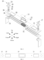
- inventions of the present disclosure provide an end cover assembly 100.
- the end cover assembly 100 includes a cover plate 12, an explosion-proof valve 14, a first electrode terminal 16, and a second electrode terminal 17.
- the cover plate 12 has a first protrusion 18, at least one second protrusion 20, and at least one third protrusion 21.
- the first protrusion 18 has a mounting hole 22.
- the at least one second protrusion 20 and the at least one third protrusion 21 are arranged at two opposite sides of the first protrusion 18 in a length direction of the cover plate 12, respectively.
- the explosion-proof valve 14 is mounted in the mounting hole 22.
- the first electrode terminal 16 and the second electrode terminal 17 are arranged on the cover plate 12 and spaced apart from each other. In the length direction of the cover plate 12, one of the at least one second protrusion 20 is closer to the first electrode terminal 16 than the first protrusion 18, and one of the at least one third protrusion 21 is closer to the second electrode terminal 17 than the first protrusion 18.
- the first protrusion 18, the at least one second protrusion 20, and the at least one third protrusion 21 are arranged on the cover plate 12.
- the at least one second protrusion 20 and the at least one third protrusion 21 are arranged at the two opposite sides of the first protrusion 18 in the length direction of the cover plate 12, respectively. Similar to a reinforcing rib, each of the protrusions can significantly reinforce strength of the cover plate 12 without increasing a thickness of the entire cover plate 12, which can reduce costs and increase an energy density.
- the required end cover assembly 100 also has a large size
- the explosion-proof valve 14 corresponding to the end cover assembly 100 also has a large size.
- the explosion-proof valve 14 is mounted at the mounting hole 22 of the first protrusion 18, which alleviates a problem of a reduction of the strength of the cover plate 12 due to a large mounting hole 22 of the explosion-proof valve 14.
- the cover plate 12 further has a liquid injection hole 23.
- the liquid injection hole 23 is configured to allow for an injection of an electrolyte solution into the battery cell 200.
- a material of the cover plate 12 is not specifically limited in the present disclosure.
- the cover plate 12 may be a polished aluminum sheet.
- the length direction of the cover plate 12 is a left-right direction.
- a width direction of the cover plate 12 is a front-rear direction.
- the cover plate 12 is provided with three protrusions, which are respectively one first protrusion 18, one second protrusion 20, and one third protrusion 21.
- the first protrusion 18 is located in a middle of the cover plate 12.
- the second protrusion 20 and the third protrusion 21 are arranged at two opposite sides (left and right sides illustrated in FIG. 1 ) of the first protrusion 18 in the length direction of the cover plate 12, respectively.
- the first electrode terminal 16 and the second electrode terminal 17 are arranged on the cover plate 12.
- the second protrusion 20 is arranged closer to the first electrode terminal 16 than the first protrusion 18, and the third protrusion 21 is arranged closer to the second electrode terminal 17 than the first protrusion 18.
- the mounting hole 22 of the explosion-proof valve 14 is defined at the first protrusion 18.
- Two second protrusions 20 are arranged at a left side of the first protrusion 18.
- Two third protrusions 21 are arranged at a right side of the first protrusion 18.
- one of the two second protrusions 20 may be arranged closer to the first electrode terminal 16 than the first protrusion 18, and one of the two third protrusions 21 may be arranged closer to the second electrode terminal 17 than the first protrusion 18.
- each electrode terminal 16 and the second electrode terminal 17 may serve as a positive terminal, and the other one of the first electrode terminal 16 and the second electrode terminal 17 may serve as a negative terminal.
- each electrode terminal may include a metallic portion 24, a connection portion 26, an insulation portion 28, and a sealing ring 30.
- the end cover assembly 100 further includes a lower plastic member 32 and a connection plate 34.
- the lower plastic member 32 is located below the cover plate 12.
- the end cover assembly 100 has a through hole 36 penetrating the cover plate 12 and the lower plastic member 32.
- the connection portion 26 passes through the through hole 36.
- An upper end of the connection portion 26 is connected to the metallic portion 24.
- a lower end of the connection portion 26 is connected to the connection plate 34.
- the metallic portion 24 is mounted in the insulation portion 28 to separate the metallic portion 24 from the cover plate 12.
- the sealing ring 30 seals a gap between the connection portion 26 and the through hole 36.
- the connection plate 34 is configured to be electrically connected to a tab of a bare cell 44.
- each of the first protrusion 18, the second protrusion 20, and the third protrusion 21 is formed on the cover plate 12 through a stamping process.
- a stamping mold when manufacturing the cover plate 12, a stamping mold may be designed. A plate with equal thickness may be stamped by a stamping device equipped with the stamping mold. The cover plate 12 with the protrusion may be obtained by blanking. Compared with a method in which a protrusion is directly formed on a surface of the cover plate 12, the method in which the protrusion is formed through the stamping process allows a part of the cover plate 12 at the other side corresponding to the protrusion to be formed as a recess, which can reduce a weight of the cover plate 12, further reducing the cost of the cover plate 12.
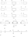
- the first electrode terminal 16, the second protrusion 20, the first protrusion 18, the third protrusion 21, and the second electrode terminal 17 are arranged sequentially in the length direction of the cover plate 12.
- the first protrusion 18, the second protrusion 20, and the third protrusion 21 are located between the first electrode terminal 16 and the second electrode terminal 17 in the length direction of the cover plate 12.
- the second protrusion 20 is arranged close to the first electrode terminal 16.
- the third protrusion 21 is arranged close to the second electrode terminal 17.
- the second protrusion 20, the first electrode terminal 16, the first protrusion 18, the second electrode terminal 17, and the third protrusion 21 are arranged sequentially in the length direction of the cover plate 12.
- the first electrode terminal 16, the first protrusion 18, and the second electrode terminal 17 are located between the second protrusion 20 and the third protrusion 21 in the length direction of the cover plate 12.
- the second protrusion 20 is arranged close to the first electrode terminal 16.
- the third protrusion 21 is arranged close to the second electrode terminal 17.
- the second protrusion 20, the first electrode terminal 16, the first protrusion 18, the third protrusion 21, and the second electrode terminal 17 are arranged sequentially in the length direction of the cover plate 12.
- the first electrode terminal 16, the first protrusion 18, and the third protrusion 21 are located between the second protrusion 20 and the second electrode terminal 17 in the length direction of the cover plate 12.
- the second protrusion 20 is arranged close to the first electrode terminal 16.
- the third protrusion 21 is arranged close to the second electrode terminal 17.
- the second protrusion 20, the first protrusion 18, and the second electrode terminal 17 are located between the first electrode terminal 16 and the third protrusion 21 in the length direction of the cover plate 12.
- the second protrusion 20 is arranged close to the first electrode terminal 16.
- the third protrusion 21 is arranged close to the second electrode terminal 17.
- the second protrusion 20 is spaced apart from the first electrode terminal 16 by a predetermined distance.
- the third protrusion 21 is spaced apart from the second electrode terminal 17 by a predetermined distance.
- the first electrode terminal 16 on the left side may be a positive terminal
- the second electrode terminal 17 on the right side may be a negative terminal.
- the distance d1 by which the first electrode terminal 16 is spaced apart from the second protrusion 20 may be unequal to the distance d2 by which the second electrode terminal 17 is spaced apart from the third protrusion 21.
- the size of the cover plate 12 can be increased compared with the second protrusion 20 being tightly attached to the first electrode terminal 16 and the third protrusion 21 being tightly attached to the second electrode terminal 17.
- the end cover assembly 100 satisfies at least one of the following relationships: 0.05 ⁇ L 2 / L 1 ⁇ 0.3 ; 0.05 ⁇ L 5 / L 1 ⁇ 0.3 ; 0.1 ⁇ L 3 / L 1 ⁇ 0.3 ; and 0.5 ⁇ L 4 / L 3 ⁇ 0.9 and 5 mm ⁇ L 4 ⁇ L 3 ⁇ 20 mm ; where L1 represents a length of the cover plate 12, L2 represents a length of each of the at least one second protrusion 20, L3 represents a length of the first protrusion 18, L4 represents a length of the explosion-proof valve 14, L5 represents a length each of the at least one third protrusion 21, and each of a length direction of the first protrusion 18, a length direction of the second protrusion 20, and a length direction of the third protrusion 21 is parallel to the length direction of the cover plate 12.
- the end cover assembly 100 when the end cover assembly 100 satisfies 0.05 ⁇ L2/L1 ⁇ 0.3, an effect of reinforcing the strength of the cover plate 12 and a reduced occupation of a space of other components such as the liquid injection hole 23 and the explosion-proof valve 14 can be ensured.
- L2/L1 may be 0.05, 0.07, 0.10, 0.12, 0.15, 0.18, 0.2, 0.22, 0.25, 0.28, 0.3, or any other value between 0.05 and 0.3.
- L5/L1 may be 0.05, 0.08, 0.10, 0.12, 0.16, 0.18, 0.21, 0.22, 0.24, 0.28, 0.3, or any other value between 0.05 and 0.3.
- L2 L5.
- L3/L1 may be 0.1, 0.12, 0.15, 0.18, 0.2, 0.22, 0.25, 0.28, 0.3, or any other value between 0.1 and 0.3.
- L4/L3 may be 0.5, 0.55, 0.6, 0.65, 0.7, 0.75, 0.8, 0.85, 0.9, or any other value between 0.5 and 0.9.
- L4-L3 may be 5 mm, 6 mm, 7 mm, 9 mm, 10 mm, 11 mm, 13 mm, 16 mm, 18 mm, 20 mm, or any other value between 5 mm and 20 mm.
- the end cover assembly 100 satisfies the following four relationships: 0.05 ⁇ L 2 / L 1 ⁇ 0.3 ; 0.05 ⁇ L 5 / L 1 ⁇ 0.3 ; 0.1 ⁇ L 3 / L 1 ⁇ 0.3 ; and 0.5 ⁇ L 4 / L 3 ⁇ 0.9 and 5 mm ⁇ L 4 ⁇ L 3 ⁇ 20 mm .
- the end cover assembly 100 satisfies one or two of the following four relationships: 0.05 ⁇ L 2 / L 1 ⁇ 0.3 ; 0.05 ⁇ L 5 / L 1 ⁇ 0.3 ; 0.1 ⁇ L3 / L 1 ⁇ 0.3 ; and 0.5 ⁇ L 4 / L 3 ⁇ 0.9 and 5 mm ⁇ L 4 ⁇ L 3 ⁇ 20 mm .
- the end cover assembly 100 satisfies at least one of the following relationships: 0.2 ⁇ W2 / W 1 ⁇ 0.9 ; 0.2 ⁇ W 5 / W 1 ⁇ 0.9 ; 0.4 ⁇ W3 / W 1 ⁇ 0.9 ; and 0.5 ⁇ W 4 / W 3 ⁇ 0.9 and 5 mm ⁇ W3 ⁇ W4 ⁇ 20 mm , where W 1 represents a width of the cover plate 12, W2 represents a width of each of the at least one second protrusion 20, W3 represents a width of the first protrusion 18, W4 represents a width of the explosion-proof valve 14, W5 represents a width each of the at least one third protrusion 21, and each of a width direction of the first protrusion 18, a width direction of the second protrusion 20, and a width direction of the third protrusion 21 is parallel to a width direction of the cover plate 12.
- the end cover assembly 100 when the end cover assembly 100 satisfies 0.2 ⁇ W2/W1 ⁇ 0.9, the effect of reinforcing the strength of the cover plate 12 and the welding quality of the cover plate 12 can be ensured.
- the second protrusion 20 would gradually extend to edges of the cover plate 12 in the width direction of the cover plate 12.
- a region for pre-spot welding needs to be reserved on each of the two side edges of the cover plate 12 in the width direction of the cover plate 12 before formal laser welding.
- W2/W1 may be 0.2, 0.25, 0.3, 0.35, 0.4, 0.45, 0.5, 0.55, 0.6, 0.65, 0.7, 0.75, 0.8, 0.85, 0.9, or any other value between 0.2 and 0.9.
- the third protrusion 21 would gradually extend to the edges of the cover plate 12 in the width direction of the cover plate 12.
- the region for pre-spot welding needs to be reserved on each of the two side edges of the cover plate 12 in the width direction of the cover plate 12 before the formal laser welding.
- W5/W1 may be 0.2, 0.23, 0.31, 0.35, 0.4, 0.42, 0.51, 0.55, 0.61, 0.67, 0.7, 0.75, 0.8, 0.85, 0.9, or any other value between 0.2 and 0.9.
- W2 W5.
- the ratio of W3 to W1 approaches 1, the first protrusion 18 would gradually extend to the edges of the cover plate 12 in the width direction of the cover plate 12.
- the region for pre-spot welding needs to be reserved on each of the two side edges of the cover plate 12 in the width direction of the cover plate 12 before the formal laser welding.
- the path design of the pre-spot welding for the cover plate 12 will be affected, hindering the laser welding between the cover plate 12 and the housing 42.
- W3/W1 may be 0.4, 0.45, 0.5, 0.55, 0.6, 0.65, 0.7, 0.75, 0.8, 0.85, 0.9, or any other value between 0.4 and 0.9.
- W4/W3 may be 0.5, 0.55, 0.6, 0.65, 0.7, 0.75, 0.8, 0.85, 0.9, or any other value between 0.5 and 0.9.
- W3-W4 may be 5 mm, 6 mm, 7 mm, 9 mm, 10 mm, 11 mm, 13 mm, 16 mm, 18 mm, 20 mm, or any other value between 5 mm and 20 mm.
- the end cover assembly 100 satisfies the following four relationships: 0.2 ⁇ W2 / W 1 ⁇ 0.9 ; 0.2 ⁇ W 5 / W 1 ⁇ 0.9 ; 0.4 ⁇ W3 / W 1 ⁇ 0.9 ; and 0.5 ⁇ W 4 / W 3 ⁇ 0.9 and 5mm ⁇ W 3 ⁇ W 4 ⁇ 20 mm .
- the end cover assembly 100 satisfies one or any two of the following four relationships: 0.2 ⁇ W 2 / W 1 ⁇ 0.9 ; 0.2 ⁇ W5 / W 1 ⁇ 0.9 ; 0.4 ⁇ W3 / W 1 ⁇ 0.9 ; and 0.5 ⁇ W 4 / W 3 ⁇ 0.9 and 5 mm ⁇ W 3 ⁇ W 4 ⁇ 20 mm .
- the end cover assembly 100 satisfies at least one of the following relationships: 0.2 ⁇ H 2 / H 1 ⁇ 1 and 0 .5 mm ⁇ H2 ⁇ 3 mm ; 0.2 ⁇ H3 / H 1 ⁇ 1 and 0 .5 mm ⁇ H3 ⁇ 3 mm ; and 0.2 ⁇ H4 / H 1 ⁇ 1 and 0 .5 mm ⁇ H4 ⁇ 3 mm , where H1 represents a thickness of the cover plate 12, H2 represents a height by which each of the at least one second protrusion 20 protrudes from the cover plate 12, H3 represents a height by which the first protrusion 18 protrudes from the cover plate 12, and H4 represents a height by which each of the at least one third protrusion 21 protrudes from the cover plate 12.
- the end cover assembly 100 when the end cover assembly 100 satisfies 0.2 ⁇ H2/H1 ⁇ 1 and 0.5 mm ⁇ H2 ⁇ 3 mm, the effect of reinforcing the strength of the cover plate 12 and a reduced occupation of a module space can be ensured.
- a total thickness of the first electrode terminal 16 and a connection sheet 38 is smaller than a height of the second protrusion 20. It should be considered that the height of the second protrusion 20, which has a function of enhancing a stress intensity of the cover plate 12, cannot be too large when the stress intensity can be increased with the height of the second protrusion 20 by a predetermined amount. This is because once the height of the second protrusion 20 is greater than the total thickness of the first electrode terminal 16 and the connection sheet 38, the second protrusion 20 will hinder later modulization of the battery cell 200 in a height direction.
- H2/H1 may be 0.2, 0.25, 0.3, 0.35, 0.4, 0.45, 0.5, 0.55, 0.6, 0.65, 0.7, 0.75, 0.8, 0.85, 0.9, 0.95, 1, or any other value between 0.2 and 1.
- H2 may be 0.5 mm, 1 mm, 1.5 mm, 2 mm, 2.5 mm, 3 mm, or any other value between 0.5 mm and 3 mm.
- a total thickness of the second electrode terminal 17 and the connection sheet 38 is smaller than a height of the third protrusion 21. It should be considered that the height of the third protrusion 21, which has a function of enhancing the stress intensity of the cover plate 12, cannot be too large when the stress intensity can be increased with the height of the third protrusion 21. This is because once the height of the third protrusion 21 is greater than the total thickness of the second electrode terminal 17 and the connection sheet 38, the third protrusion 21 will hinder the later modulization of the battery cell 200 in the height direction.
- H4/H1 may be 0.2, 0.24, 0.32, 0.35, 0.4, 0.46, 0.5, 0.55, 0.6, 0.65, 0.7, 0.75, 0.8, 0.85, 0.91, 0.95, 1, or any other value between 0.2 and 1.
- H4 may be 0.5 mm, 1 mm, 1.5 mm, 2 mm, 2.5 mm, 3 mm, or any other value between 0.5 mm and 3 mm.
- H2 H4.
- H3 When H3/H1 ⁇ 0.2 and H3 ⁇ 0.5mm, H3 is too small, which leads to the poor effect of reinforcing the strength of the cover plate 12. When H3/H1>1 and H3>3 mm, H3 is too large, which leads to the high molding difficulty and easily results in the occupation of the module space.
- H3/H1 may be 0.2, 0.25, 0.3, 0.35, 0.4, 0.45, 0.5, 0.55, 0.6, 0.65, 0.7, 0.75, 0.8, 0.85, 0.9, 0.95, 1, or any other value between 0.2 and 1.
- H3 may be 0.5 mm, 1 mm, 1.5 mm, 2 mm, 2.5 mm, 3 mm, or any other value between 0.5 mm and 3 mm. H3 may be equal or unequal to H2.
- the end cover assembly 100 of the present disclosure can provide at least the following effects.
- a battery cell 200 includes the end cover assembly 100 according to any of the above-mentioned embodiments.
- the first protrusion 18 and the at least one second protrusion 20 are arranged on the cover plate 12.
- the at least one second protrusion 20 is arranged at each of the two opposite sides of the first protrusion 18 in the length direction of the cover plate 12.
- the protrusion can significantly reinforce the strength of the cover plate 12 without increasing the thickness of the cover plate 12, which can reduce the cost and increase the energy density.
- the battery cell 200 further includes a housing 42 and the bare cell 44.
- the housing 42 has an accommodation chamber 46 formed in the housing 42.
- the housing 42 has an opening 48 defined on a side of the housing 42.
- the end cover assembly 100 is mounted at the opening 48 to seal the accommodation chamber 46.
- the connection plate 34 of the end cover assembly 100 is electrically connected to a tab of the bare cell 44.
- At least one bare cell 44 may be arranged in the accommodation chamber 46. As illustrated in FIG. 10 , two bare cells 44 are arranged in the accommodation cavity 46. The two bare cells 44 are connected in series or in parallel.
- a battery module 300 includes the battery cell 200 according to the above-mentioned embodiments.
- the first protrusion 18, the at least one second protrusion 20, and the at least one third protrusion 21 are arranged on the cover plate 12.
- the at least one second protrusion 20 and the at least one third protrusion 21 are arranged at the two opposite sides of the first protrusion 18 in the length direction of the cover plate 12, respectively.
- the protrusions can significantly reinforce the strength of the cover plate 12 without increasing the thickness of the entire cover plate 12, which can reduce the cost and increase the energy density.
- the battery module 300 may include one battery cell 200 or a plurality of battery cells 200.
- the plurality of battery cells 200 may be electrically connected in series, in parallel, or in series and parallel.
- the battery module 300 further includes a casing.
- the battery cell 200 may be placed in the casing.
- the battery module 300 includes a plurality of battery cells 200 arranged side by side. Two first electrode terminals 16 or two second electrode terminals 17 of two adjacent battery cells 200 of the plurality of battery cells 200 are electrically connected to each other by a connection sheet 38. One of the at least one second protrusion 20 or one of the at least one third protrusion 21 of each of the plurality of battery cells 200 is electrically connected to a connection sheet 38 close to the one second protrusion or the one third protrusion by a sampling connector 40.
- the second protrusion 20 or the third protrusion 21 can be used as a sampling protrusion to reduce the costs.
- the end cover assembly 100 spans by a large distance.
- connection sheet 38 such as an aluminum bar sheet
- the third protrusion 21 of the front battery cell 200 of the two battery cells 200 serves as the sampling protrusion and is electrically connected to the connection sheet 38 by the sampling connector 40.
- the second protrusion 20 of the rear battery cell 200 of the two battery cells 200 serves as the sampling protrusion and is electrically connected to the connection sheet 38 by the sampling connector 40.
- the first electrode terminal 16 of the front battery cell 200 at a left side is a negative terminal.
- the second electrode terminal 17 of the front battery cell 200 at a right side is a positive terminal.
- the first electrode terminal 16 of the rear battery cell 200 at the left side is a positive terminal.
- the second electrode terminal 17 of the rear battery cell 200 at the right side is a negative terminal.
- the second protrusion 20 close to the positive electrode is electrically connected to the connection sheet 38 by the sampling connector 40, in such a manner that the housing 42 of the battery cell 200 is charged. Data such as a voltage of the battery can be obtained through the connection sheet 38 connected to the negative electrode and the housing 42.
- connection sheets 38 when more than two battery cells 200 are provided, these battery cells are connected in series by the connection sheets 38.
- the second protrusion 20 close to one overall positive electrode in the battery module is connected to the connection sheet 38 by the sampling connector 40 to charge the housing 42 of a corresponding one of the battery cells 200.
- the third protrusion 21 close to one overall negative electrode in the battery module is connected to the connection sheet 38 by the sampling connector 40. Therefore, it is unnecessary to design a long collection harness for a voltage signal collection, thereby reducing the costs.
- an energy storage device includes the battery cell 200 according to any of the above-mentioned embodiments or the battery module 300 according to any of the above-mentioned embodiments.
- the first protrusion 18, the at least one second protrusion 20, and the at least one third protrusion 21 are arranged on the cover plate 12.
- the at least one second protrusion 20 and the at least one third protrusion 21 are arranged at the two opposite sides of the first protrusion 18 in the length direction of the cover plate 12, respectively.
- the protrusions can significantly reinforce the strength of the cover plate 12 without increasing the thickness of the entire cover plate 12, which can reduce the costs and increase the energy density.
- the energy storage device may further include a cluster rack and a shell.
- the energy storage device includes one or more battery modules 300.
- the one or more battery modules 300 may be mounted on the cluster rack to form a battery cluster.
- the plurality of battery modules 300 may be arranged on the cluster rack in array and may be electrically connected in series, in parallel, or in series and parallel.
- One or more battery clusters may be placed in the shell.
- the energy storage device includes one or more battery cells 200.
- the one or more battery cells 200 may be mounted on the cluster rack to form a battery cluster.
- the plurality of battery cells 200 may be arranged on the cluster rack in array and may be electrically connected in series, in parallel, or in series and parallel.
- One or more battery clusters may be placed in the shell.
- the energy storage device may include, but is not limited to, an energy storage container, a household energy storage cabinet, and other energy storage devices.
Landscapes
- Chemical & Material Sciences (AREA)
- Chemical Kinetics & Catalysis (AREA)
- Electrochemistry (AREA)
- General Chemical & Material Sciences (AREA)
- Gas Exhaust Devices For Batteries (AREA)
- Sealing Battery Cases Or Jackets (AREA)
Applications Claiming Priority (1)
| Application Number | Priority Date | Filing Date | Title |
|---|---|---|---|
| CN202321413171.8U CN219998358U (zh) | 2023-06-05 | 2023-06-05 | 端盖组件、电池单体、电池模组和储能设备 |
Publications (1)
| Publication Number | Publication Date |
|---|---|
| EP4475284A1 true EP4475284A1 (de) | 2024-12-11 |
Family
ID=88613885
Family Applications (1)
| Application Number | Title | Priority Date | Filing Date |
|---|---|---|---|
| EP24162233.1A Pending EP4475284A1 (de) | 2023-06-05 | 2024-03-08 | Endkappenanordnung, batteriezelle, batteriemodul und energiespeichervorrichtung |
Country Status (4)
| Country | Link |
|---|---|
| US (1) | US20240405330A1 (de) |
| EP (1) | EP4475284A1 (de) |
| CN (1) | CN219998358U (de) |
| WO (1) | WO2024250409A1 (de) |
Cited By (1)
| Publication number | Priority date | Publication date | Assignee | Title |
|---|---|---|---|---|
| CN120127303A (zh) * | 2025-02-21 | 2025-06-10 | 蜂巢能源科技股份有限公司 | 盖板组件、单体电池及电池包 |
Families Citing this family (3)
| Publication number | Priority date | Publication date | Assignee | Title |
|---|---|---|---|---|
| CN117374488B (zh) * | 2023-12-07 | 2024-02-20 | 蜂巢能源科技股份有限公司 | 盖板及电池 |
| CN223427592U (zh) * | 2024-09-05 | 2025-10-10 | 宁德时代新能源科技股份有限公司 | 电池单体、电池装置和用电装置 |
| CN119944182B (zh) * | 2025-01-22 | 2025-12-02 | 蜂巢能源科技股份有限公司 | 一种电池 |
Citations (3)
| Publication number | Priority date | Publication date | Assignee | Title |
|---|---|---|---|---|
| CN206727177U (zh) * | 2017-03-16 | 2017-12-08 | 宁德时代新能源科技股份有限公司 | 二次电池及电池包 |
| EP3471166A1 (de) * | 2017-10-10 | 2019-04-17 | Contemporary Amperex Technology Co., Limited | Kappenanordnung für eine zweite batterie und zweite batterie |
| CN214898622U (zh) * | 2021-06-29 | 2021-11-26 | 中航锂电(厦门)科技有限公司 | 电池盖板组件和电池 |
Family Cites Families (4)
| Publication number | Priority date | Publication date | Assignee | Title |
|---|---|---|---|---|
| JP6065368B2 (ja) * | 2012-02-01 | 2017-01-25 | 株式会社Gsユアサ | 組電池 |
| JP6707367B2 (ja) * | 2016-02-29 | 2020-06-10 | 三洋電機株式会社 | 二次電池及び組電池 |
| CN207489931U (zh) * | 2017-11-27 | 2018-06-12 | 欣旺达电子股份有限公司 | 动力电池盖板及其动力电池 |
| CN217134590U (zh) * | 2022-06-10 | 2022-08-05 | 宁德时代新能源科技股份有限公司 | 端盖组件、电池单体、电池及用电装置 |
-
2023
- 2023-06-05 CN CN202321413171.8U patent/CN219998358U/zh active Active
- 2023-08-07 WO PCT/CN2023/111365 patent/WO2024250409A1/zh not_active Ceased
-
2024
- 2024-02-29 US US18/590,994 patent/US20240405330A1/en active Pending
- 2024-03-08 EP EP24162233.1A patent/EP4475284A1/de active Pending
Patent Citations (3)
| Publication number | Priority date | Publication date | Assignee | Title |
|---|---|---|---|---|
| CN206727177U (zh) * | 2017-03-16 | 2017-12-08 | 宁德时代新能源科技股份有限公司 | 二次电池及电池包 |
| EP3471166A1 (de) * | 2017-10-10 | 2019-04-17 | Contemporary Amperex Technology Co., Limited | Kappenanordnung für eine zweite batterie und zweite batterie |
| CN214898622U (zh) * | 2021-06-29 | 2021-11-26 | 中航锂电(厦门)科技有限公司 | 电池盖板组件和电池 |
Cited By (1)
| Publication number | Priority date | Publication date | Assignee | Title |
|---|---|---|---|---|
| CN120127303A (zh) * | 2025-02-21 | 2025-06-10 | 蜂巢能源科技股份有限公司 | 盖板组件、单体电池及电池包 |
Also Published As
| Publication number | Publication date |
|---|---|
| US20240405330A1 (en) | 2024-12-05 |
| CN219998358U (zh) | 2023-11-10 |
| WO2024250409A1 (zh) | 2024-12-12 |
Similar Documents
| Publication | Publication Date | Title |
|---|---|---|
| US20240405330A1 (en) | End cover assembly, battery cell, battery module, and energy storage device | |
| KR102330378B1 (ko) | 디개싱 유로를 구비한 배터리 팩 | |
| EP3660974B1 (de) | Batteriemodul mit wärmeableitungsplatte | |
| EP3675216B1 (de) | Batteriepack | |
| US7550227B2 (en) | Secondary battery | |
| KR102378374B1 (ko) | 버스바를 구비한 배터리 모듈 및 배터리 팩 | |
| KR102177694B1 (ko) | 버스바 어셈블리를 포함하는 배터리 모듈 | |
| US8748021B2 (en) | Battery module | |
| US20210313657A1 (en) | Battery Module with ICB Assembly in Space-Saving Structure | |
| EP3651237A1 (de) | Batteriepack mit verbesserter montagestruktur | |
| US12308455B2 (en) | Battery pack, electronic device and vehicle | |
| US20120288744A1 (en) | Battery module | |
| US20100203363A1 (en) | Connector assembly and battery pack having the same | |
| JP2001110381A (ja) | 角形密閉式電池 | |
| EP4621948A1 (de) | Batteriezelle, batterie und elektrische vorrichtung | |
| KR102937187B1 (ko) | 배터리 모듈, 이를 포함하는 배터리 팩, 및 자동차 | |
| US12009550B1 (en) | Lower plastic assembly, end cover assembly, energy-storage apparatus, and electronic device | |
| CN116097517B (zh) | 电池、用电设备和电池的制备方法 | |
| KR20200080069A (ko) | 배터리 모듈, 이러한 배터리 모듈을 포함하는 배터리 팩 및 이러한 배터리 팩을 포함하는 자동차 | |
| US6946219B2 (en) | Sealed prismatic battery connected via openings with conductive connection plates | |
| JP2013020731A (ja) | 二次電池 | |
| CN220474836U (zh) | 一种下塑胶件、盖板组件及动力电池 | |
| US12362436B2 (en) | Power storage device | |
| CN219144439U (zh) | 电池模组及电池包 | |
| CN218275000U (zh) | 单体电池与电池包 |
Legal Events
| Date | Code | Title | Description |
|---|---|---|---|
| PUAI | Public reference made under article 153(3) epc to a published international application that has entered the european phase |
Free format text: ORIGINAL CODE: 0009012 |
|
| STAA | Information on the status of an ep patent application or granted ep patent |
Free format text: STATUS: THE APPLICATION HAS BEEN PUBLISHED |
|
| AK | Designated contracting states |
Kind code of ref document: A1 Designated state(s): AL AT BE BG CH CY CZ DE DK EE ES FI FR GB GR HR HU IE IS IT LI LT LU LV MC ME MK MT NL NO PL PT RO RS SE SI SK SM TR |
|
| RAP1 | Party data changed (applicant data changed or rights of an application transferred) |
Owner name: HITHIUM TECH HK LIMITED |
|
| STAA | Information on the status of an ep patent application or granted ep patent |
Free format text: STATUS: REQUEST FOR EXAMINATION WAS MADE |
|
| 17P | Request for examination filed |
Effective date: 20250610 |