EP4475320A1 - Séparateur pour élément électrochimique, son procédé de fabrication et élément électrochimique le contenant - Google Patents
Séparateur pour élément électrochimique, son procédé de fabrication et élément électrochimique le contenant Download PDFInfo
- Publication number
- EP4475320A1 EP4475320A1 EP23875072.3A EP23875072A EP4475320A1 EP 4475320 A1 EP4475320 A1 EP 4475320A1 EP 23875072 A EP23875072 A EP 23875072A EP 4475320 A1 EP4475320 A1 EP 4475320A1
- Authority
- EP
- European Patent Office
- Prior art keywords
- polymer binder
- polymer
- coating layer
- separator
- weight
- Prior art date
- Legal status (The legal status is an assumption and is not a legal conclusion. Google has not performed a legal analysis and makes no representation as to the accuracy of the status listed.)
- Pending
Links
Images
Classifications
-
- H—ELECTRICITY
- H01—ELECTRIC ELEMENTS
- H01M—PROCESSES OR MEANS, e.g. BATTERIES, FOR THE DIRECT CONVERSION OF CHEMICAL ENERGY INTO ELECTRICAL ENERGY
- H01M50/00—Constructional details or processes of manufacture of the non-active parts of electrochemical cells other than fuel cells, e.g. hybrid cells
- H01M50/40—Separators; Membranes; Diaphragms; Spacing elements inside cells
- H01M50/409—Separators, membranes or diaphragms characterised by the material
- H01M50/411—Organic material
-
- H—ELECTRICITY
- H01—ELECTRIC ELEMENTS
- H01M—PROCESSES OR MEANS, e.g. BATTERIES, FOR THE DIRECT CONVERSION OF CHEMICAL ENERGY INTO ELECTRICAL ENERGY
- H01M50/00—Constructional details or processes of manufacture of the non-active parts of electrochemical cells other than fuel cells, e.g. hybrid cells
- H01M50/40—Separators; Membranes; Diaphragms; Spacing elements inside cells
- H01M50/409—Separators, membranes or diaphragms characterised by the material
- H01M50/446—Composite material consisting of a mixture of organic and inorganic materials
-
- H—ELECTRICITY
- H01—ELECTRIC ELEMENTS
- H01M—PROCESSES OR MEANS, e.g. BATTERIES, FOR THE DIRECT CONVERSION OF CHEMICAL ENERGY INTO ELECTRICAL ENERGY
- H01M10/00—Secondary cells; Manufacture thereof
- H01M10/05—Accumulators with non-aqueous electrolyte
- H01M10/052—Li-accumulators
-
- H—ELECTRICITY
- H01—ELECTRIC ELEMENTS
- H01M—PROCESSES OR MEANS, e.g. BATTERIES, FOR THE DIRECT CONVERSION OF CHEMICAL ENERGY INTO ELECTRICAL ENERGY
- H01M50/00—Constructional details or processes of manufacture of the non-active parts of electrochemical cells other than fuel cells, e.g. hybrid cells
- H01M50/40—Separators; Membranes; Diaphragms; Spacing elements inside cells
- H01M50/403—Manufacturing processes of separators, membranes or diaphragms
-
- H—ELECTRICITY
- H01—ELECTRIC ELEMENTS
- H01M—PROCESSES OR MEANS, e.g. BATTERIES, FOR THE DIRECT CONVERSION OF CHEMICAL ENERGY INTO ELECTRICAL ENERGY
- H01M50/00—Constructional details or processes of manufacture of the non-active parts of electrochemical cells other than fuel cells, e.g. hybrid cells
- H01M50/40—Separators; Membranes; Diaphragms; Spacing elements inside cells
- H01M50/409—Separators, membranes or diaphragms characterised by the material
-
- H—ELECTRICITY
- H01—ELECTRIC ELEMENTS
- H01M—PROCESSES OR MEANS, e.g. BATTERIES, FOR THE DIRECT CONVERSION OF CHEMICAL ENERGY INTO ELECTRICAL ENERGY
- H01M50/00—Constructional details or processes of manufacture of the non-active parts of electrochemical cells other than fuel cells, e.g. hybrid cells
- H01M50/40—Separators; Membranes; Diaphragms; Spacing elements inside cells
- H01M50/409—Separators, membranes or diaphragms characterised by the material
- H01M50/411—Organic material
- H01M50/414—Synthetic resins, e.g. thermoplastics or thermosetting resins
- H01M50/417—Polyolefins
-
- H—ELECTRICITY
- H01—ELECTRIC ELEMENTS
- H01M—PROCESSES OR MEANS, e.g. BATTERIES, FOR THE DIRECT CONVERSION OF CHEMICAL ENERGY INTO ELECTRICAL ENERGY
- H01M50/00—Constructional details or processes of manufacture of the non-active parts of electrochemical cells other than fuel cells, e.g. hybrid cells
- H01M50/40—Separators; Membranes; Diaphragms; Spacing elements inside cells
- H01M50/409—Separators, membranes or diaphragms characterised by the material
- H01M50/431—Inorganic material
-
- H—ELECTRICITY
- H01—ELECTRIC ELEMENTS
- H01M—PROCESSES OR MEANS, e.g. BATTERIES, FOR THE DIRECT CONVERSION OF CHEMICAL ENERGY INTO ELECTRICAL ENERGY
- H01M50/00—Constructional details or processes of manufacture of the non-active parts of electrochemical cells other than fuel cells, e.g. hybrid cells
- H01M50/40—Separators; Membranes; Diaphragms; Spacing elements inside cells
- H01M50/409—Separators, membranes or diaphragms characterised by the material
- H01M50/443—Particulate material
-
- H—ELECTRICITY
- H01—ELECTRIC ELEMENTS
- H01M—PROCESSES OR MEANS, e.g. BATTERIES, FOR THE DIRECT CONVERSION OF CHEMICAL ENERGY INTO ELECTRICAL ENERGY
- H01M50/00—Constructional details or processes of manufacture of the non-active parts of electrochemical cells other than fuel cells, e.g. hybrid cells
- H01M50/40—Separators; Membranes; Diaphragms; Spacing elements inside cells
- H01M50/409—Separators, membranes or diaphragms characterised by the material
- H01M50/449—Separators, membranes or diaphragms characterised by the material having a layered structure
- H01M50/451—Separators, membranes or diaphragms characterised by the material having a layered structure comprising layers of only organic material and layers containing inorganic material
-
- H—ELECTRICITY
- H01—ELECTRIC ELEMENTS
- H01M—PROCESSES OR MEANS, e.g. BATTERIES, FOR THE DIRECT CONVERSION OF CHEMICAL ENERGY INTO ELECTRICAL ENERGY
- H01M50/00—Constructional details or processes of manufacture of the non-active parts of electrochemical cells other than fuel cells, e.g. hybrid cells
- H01M50/40—Separators; Membranes; Diaphragms; Spacing elements inside cells
- H01M50/409—Separators, membranes or diaphragms characterised by the material
- H01M50/449—Separators, membranes or diaphragms characterised by the material having a layered structure
- H01M50/457—Separators, membranes or diaphragms characterised by the material having a layered structure comprising three or more layers
-
- H—ELECTRICITY
- H01—ELECTRIC ELEMENTS
- H01M—PROCESSES OR MEANS, e.g. BATTERIES, FOR THE DIRECT CONVERSION OF CHEMICAL ENERGY INTO ELECTRICAL ENERGY
- H01M50/00—Constructional details or processes of manufacture of the non-active parts of electrochemical cells other than fuel cells, e.g. hybrid cells
- H01M50/40—Separators; Membranes; Diaphragms; Spacing elements inside cells
- H01M50/489—Separators, membranes, diaphragms or spacing elements inside the cells, characterised by their physical properties, e.g. swelling degree, hydrophilicity or shut down properties
-
- H—ELECTRICITY
- H01—ELECTRIC ELEMENTS
- H01M—PROCESSES OR MEANS, e.g. BATTERIES, FOR THE DIRECT CONVERSION OF CHEMICAL ENERGY INTO ELECTRICAL ENERGY
- H01M50/00—Constructional details or processes of manufacture of the non-active parts of electrochemical cells other than fuel cells, e.g. hybrid cells
- H01M50/40—Separators; Membranes; Diaphragms; Spacing elements inside cells
- H01M50/489—Separators, membranes, diaphragms or spacing elements inside the cells, characterised by their physical properties, e.g. swelling degree, hydrophilicity or shut down properties
- H01M50/491—Porosity
-
- H—ELECTRICITY
- H01—ELECTRIC ELEMENTS
- H01M—PROCESSES OR MEANS, e.g. BATTERIES, FOR THE DIRECT CONVERSION OF CHEMICAL ENERGY INTO ELECTRICAL ENERGY
- H01M2220/00—Batteries for particular applications
- H01M2220/20—Batteries in motive systems, e.g. vehicle, ship, plane
-
- Y—GENERAL TAGGING OF NEW TECHNOLOGICAL DEVELOPMENTS; GENERAL TAGGING OF CROSS-SECTIONAL TECHNOLOGIES SPANNING OVER SEVERAL SECTIONS OF THE IPC; TECHNICAL SUBJECTS COVERED BY FORMER USPC CROSS-REFERENCE ART COLLECTIONS [XRACs] AND DIGESTS
- Y02—TECHNOLOGIES OR APPLICATIONS FOR MITIGATION OR ADAPTATION AGAINST CLIMATE CHANGE
- Y02E—REDUCTION OF GREENHOUSE GAS [GHG] EMISSIONS, RELATED TO ENERGY GENERATION, TRANSMISSION OR DISTRIBUTION
- Y02E60/00—Enabling technologies; Technologies with a potential or indirect contribution to GHG emissions mitigation
- Y02E60/10—Energy storage using batteries
Definitions
- the present disclosure relates to a separator for an electrochemical device, a manufacturing method thereof, and an electrochemical device including the same, and specifically to a separator for an electrochemical device, which improves the cohesive force between the polymer binders and can prevent the coating layer from detaching from a polymer substrate by forming a coating layer with a polymer binder mixture containing a plurality of polymer binders having different glass transition temperatures, a manufacturing method thereof, and an electrochemical device including the same.
- a separator among components of an electrochemical device contains a polymer substrate having a porous structure located between a cathode and an anode, and serves to isolate the cathode and the anode, prevent electrical short circuit between the two electrodes, and pass an electrolyte and ions.
- the separator itself does not participate in the electrochemical reaction, but physical properties such as wettability to an electrolyte solution, degree of porosity, and thermal contraction rate affect the performance and safety of the electrochemical device.
- an inorganic material may be added to the coating layer in order to improve the mechanical strength of the separator, or an inorganic material or hydrate for improving the flame retardancy and heat resistance of the polymer substrate may be added to the coating layer.
- the separator may be bonded to the electrode through a lamination process, and in order to ensure adhesive force between the electrode and the separator, polymer binders may be added to a composition for forming the coating layer of the separator.
- the porous polymer substrate has a problem in that shrinkage occurs when exposed to high temperatures, and due to this, when the separator shrinks within a lithium-ion battery, the cathode and the anode come into contact, causing an internal short circuit so that there is a problem in that thermal runaway occurs due to a decomposition reaction between the electrolyte solution and the active material.
- a technical problem to be achieved by the present disclosure is to provide a separator for an electrochemical device, which improves the cohesive force between inorganic particles and the polymer binders and can prevent the coating layer from detaching due to impact during the process of cutting and handling the separator and assembling the battery, a manufacturing method thereof, and an electrochemical device including the same.
- the polymer binder mixture contains a first polymer binder, a second polymer binder, and a third polymer binder, and the first polymer binder, the second polymer binder, and the third polymer binder may satisfy Mathematical Equation 1 below.
- the first polymer binder may have a glass transition temperature of -40°C or higher to -20°C or lower.
- the second polymer binder may have a glass transition temperature of 0°C or higher to 20°C or lower.
- the third polymer binder may have a glass transition temperature of 30°C or higher to 60°C or lower.
- the first polymer binder may have a glass transition temperature of -40°C or higher to -20°C or lower
- the second polymer binder may have a glass transition temperature of 0°C or higher to 20°C or lower
- the third polymer binder may have a glass transition temperature of 30°C or higher to 60°C or lower.
- the first polymer binder may be contained in an amount of 5 parts by weight or more to 15 parts by weight or less based on 100 parts by weight of the polymer binder mixture
- the second polymer binder may be contained in an amount of 30 parts by weight or more to 50 parts by weight or less based on 100 parts by weight of the polymer binder mixture
- the third polymer binder may be contained in an amount of 40 parts by weight or more to 60 parts by weight or less based on 100 parts by weight of the polymer binder mixture.
- the amount of the first polymer binder contained in one portion to which the polymer substrate of the thickness of the coating layer is adjacent may be greater than that of the first polymer binder contained in the other portion to which the polymer substrate thereof is not adjacent.
- the amount of the third polymer binder contained in the other portion to which the polymer substrate of the thickness of the coating layer is not adjacent may be greater than that of the third polymer binder contained in one portion to which the polymer substrate thereof is adjacent.
- the second polymer binder may be contained in a uniform amount in the coating layer.
- One embodiment of the present disclosure is a method for manufacturing the separator for an electrochemical device, and provides a method for manufacturing a separator for an electrochemical device, the method including steps of: coating at least one surface of the polymer substrate with a composition for forming a coating layer, which includes the polymer binder mixture containing three or more polymer binders having different glass transition temperatures and the inorganic particles; and drying the coated composition for forming a coating layer to form the coating layer.
- the drying temperature may be 30°C or higher to 70°C or lower.
- One embodiment of the present disclosure provides an electrochemical device including a cathode, an anode, and a separator interposed between the cathode and the anode, wherein the separator is the separator for an electrochemical device.
- the separator for an electrochemical device can improve the adhesive force between the polymer substrate and the coating layer by improving the cohesive force between the inorganic particles and the polymer binders.
- the method for manufacturing a separator for an electrochemical device can improve the cohesive force between the inorganic particles and the polymer binders by controlling the temperature of the drying process, and can improve the adhesive force between the polymer substrate and the coating layer and the adhesive force between the electrode and the coating layer respectively by adjusting the contents of the first polymer binder and the third polymer binder depending on the position of the coating layer.
- the electrochemical device can prevent the coating layer from detaching due to impact during the process of cutting and handling the separator and the process of assembling the battery.
- connection used in the present specification is a concept which not only means that any of the members are directly connected, but also includes that other members are further interposed between the members and indirectly connected.
- the characteristic of "having pores” refers to the fact that an object contains a plurality of pores so that gaseous and/or liquid fluid can pass to one side surface of the object and to the other side surface thereof by a structure in which the pores are connected to each other.
- the separator has porous characteristics including a large number of pores, and serves as a porous ion-conducting barrier that allows ions to pass while blocking electrical contact between the anode and the cathode in an electrochemical device.
- One embodiment of the present disclosure provides a separator for an electrochemical device, including: a polymer substrate containing a plurality of pores; and a coating layer which is provided on at least one surface of the polymer substrate, contains a plurality of pores, and includes inorganic particles and a polymer binder mixture, wherein the polymer binder mixture contains three or more polymer binders having different glass transition temperatures.
- the separator for an electrochemical device can improve the adhesive force between the polymer substrate and the coating layer by improving the cohesive force between the inorganic particles and the polymer binders.
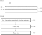
- FIG. 1 is a schematic diagram of a separator 100 for an electrochemical device according to one embodiment of the present disclosure.
- the separator 100 for an electrochemical device which is one embodiment of the present disclosure, will be described in detail.
- the separator for an electrochemical device can enable lithium ions to pass through while preventing short circuit by including a polymer substrate 110 containing a plurality of pores and thus electrically insulating the anode and cathode, and can prevent thermal runaway of the battery by shutting down the pores since the polymer substrate melts in the case of high temperature runaway during battery use.
- the polymer substrate serves as a porous ion-conducting barrier that allows ions to pass while blocking electrical contact between the anode and the cathode.
- a plurality of pores are formed inside the polymer substrate, and the pores have a structure in which they are interconnected so that it is preferable that gas or liquid can pass to one side surface of the separator and to the other side surface thereof.
- a substrate having high resistance to an electrolyte solution which is an organic solvent
- the polymer substrate 110 can be used without particular restrictions as long as it can be used as a separator material for secondary batteries.
- resins such as polyolefin-based resins including polyethylene, polypropylene, and polybutene, polyvinyl chloride, polyethylene terephthalate, polycycloolefin, polyether sulfone, polyamide, polyimide, polyamideimide, polyaramid, nylon, polytetrafluoroethylene, mixtures thereof, or copolymers thereof.
- polyolefin-based resins may be used, and more preferably, polyethylene resins may be used.
- Polyolefin-based resins among these have excellent applicability of a mixture for forming a coating layer, and can increase the capacity per volume by increasing the ratio of an electrode active material layer within the battery by thinning the thickness of the separator for secondary batteries.
- the polymer substrate 110 may have a thickness of 1 ⁇ m or more to 100 ⁇ m or less.
- the polymer substrate may have a thickness of 10 ⁇ m or more to 95 ⁇ m or less, 15 ⁇ m or more to 90 ⁇ m or less, 20 ⁇ m or more to 85 ⁇ m or less, 25 ⁇ m or more to 80 ⁇ m or less, 30 ⁇ m or more to 75 ⁇ m or less, 35 ⁇ m or more to 70 ⁇ m or less, 40 ⁇ m or more to 65 ⁇ m or less, 45 ⁇ m or more to 60 ⁇ m or less, 50 ⁇ m or more to 65 ⁇ m or less, or 55 ⁇ m or more to 60 ⁇ m or less.
- the polymer substrate may have a thickness of 1 ⁇ m or more to 30 ⁇ m or less.
- the volume of the electrochemical device can be minimized, and the anode and cathode can be electrically insulated by adjusting the thickness of the polymer substrate in the above-described range.
- the pores contained in the polymer substrate may have a size of 1 nm or more to 100 nm or less.
- the pores contained in the polymer substrate may have a size of 5 nm or more to 95 nm or less, 10 nm or more to 90 nm or less, 15 nm or more to 85 nm or less, 20 nm or more to 80 nm or less, 25 nm or more to 75 nm or less, 30 nm or more to 70 nm or less, 35 nm or more to 65 nm or less, 40 nm or more to 60 nm or less, or 45 nm or more to 55 nm or less.
- the pores contained in the polymer substrate may have a size of 20 nm or more to 60 nm or less.
- the permeability of lithium ions can be adjusted by adjusting the size of the pores contained in the polymer substrate in the above-described range.
- the pore size of the polymer substrate 110 and/or the coating layer 130 may be measured using the BET 6-point method by the nitrogen gas adsorption distribution technique using a scanning electron microscope (SEM) image, a mercury porosimeter, a capillary flow porometer, or a porosimetry analyzer (Bell Japan Inc, Belsorp-II mini). At this time, it may be advantageous to use a capillary flow porometer.
- SEM scanning electron microscope
- the polymer substrate may have a porous sheet form having a plurality of pores.
- the pores include open pores, and since the open pores are formed in a structure in which they are interconnected to each other, gas or liquid can pass to one side surface of the polymer substrate and to the other side surface thereof.
- the polymer substrate has an air permeability of 2,000 sec/100 ml or less and a porosity of 30 vol% to 60 vol% in terms of battery output and cycle characteristics.
- the air permeability (sec/100 ml) refers to the time (seconds) it takes for 100 ml of air to pass through a sample such as a polymer substrate or separator of 1 square inch in size under constant air pressure.
- the air permeability may be measured according to standard regulations in the present technical field.
- the air permeability may be measured using a known Gurley Densometer in accordance with ASTM D 726-58 or ASTM D726-94, and for example, it may be the time in second units for 100 ml of air to pass through 1 square inch (or 6.54 cm 2 ) of a sample under the pressure of air of 0.304 (kPa) or the pressure of water of 1.215 kN/m 2 .
- the air permeability may be expressed in terms of time (seconds) by measuring the time it takes for 100 ml of air to pass through a 1 square inch sample under a constant pressure of 4.8 inch of H 2 O at room temperature according to the Gurley measurement method of the Japanese industrial standard (JIS-P8117).
- the air permeability can be measured using, for example, Asahi seico's EG01-55-1MR equipment according to the standard regulations.
- the porosity refers to the ratio of the volume occupied by pores to the total volume, and vol% is used as a unit thereof, and can be used interchangeably with terms such as porosity rate and porosity.
- the measurement of the porosity is not particularly limited, and methods known in the present technical field may be applied. For example, it may be measured by the Brunauer-Emmett-Teller (BET) measurement method using nitrogen gas, the water intrusion porosimeter method, the capillary flow porometer, or the Hg porosimeter.
- BET Brunauer-Emmett-Teller
- the true density of the polymer substrate may be calculated from the density (apparent density) of the obtained polymer substrate, the composition ratio of the materials included in the polymer substrate, and the density of each component, and the porosity of the polymer substrate may be calculated from the difference between the apparent density and the net density.
- it includes a coating layer 130 which is provided on at least one surface of the polymer substrate 110, contains a plurality of pores, and includes inorganic particles and a polymer binder mixture. It can prevent the polymer substrate 110 from being shrunk at high temperatures and can prevent an internal short circuit from occurring when the anode and cathode within the battery come into contact by including a coating layer 130 which is provided on at least one surface of the polymer substrate 110, contains a plurality of pores, and includes inorganic particles and a polymer binder mixture as described above.
- the coating layer 130 may have a thickness of 0.1 ⁇ m or more to 20 ⁇ m or less. Specifically, the coating layer may have a thickness of 1 ⁇ m or more to 19 ⁇ m or less, 2 ⁇ m or more to 18 ⁇ m or less, 3 ⁇ m or more to 17 ⁇ m or less, 4 ⁇ m or more to 16 ⁇ m or less, 5 ⁇ m or more to 15 ⁇ m or less, 6 ⁇ m or more to 14 ⁇ m or less, 7 ⁇ m or more to 12 ⁇ m or less, 8 ⁇ m or more to 11 ⁇ m or less, or 9 ⁇ m or more to 10 ⁇ m or less. It is possible to control the thickness of the separator for an electrochemical device and implement weight reduction at the same time, and prevent shrinkage of the polymer substrate at high temperatures by adjusting the thickness of the coating layer in the above-described range.
- the thickness of the polymer substrate and/or the coating layer can be measured by applying a contact thickness gauge.
- the contact-type thickness gauge may be used as, for example, VL-50S-B from Mitutoyo.
- the coating layer 130 is provided on at least one surface of the polymer substrate 110. Specifically, the coating layer 130 is provided on one surface of the polymer substrate 110 or on both surfaces of the polymer substrate 110. As described above, the coating layer 130 is provided on at least one surface of the polymer substrate 110, and thus shrinkage of the polymer substrate 110 at high temperatures can be minimized.
- the coating layer may be formed using a composition for forming a coating layer, which includes the inorganic particles and the polymer binder mixture.
- a composition for forming a coating layer which includes the inorganic particles and the polymer binder mixture, is used, and thus the convenience of working to form a coating layer can be improved, and the viscosity of the composition for forming a coating layer can be easily adjusted.
- the composition for forming a coating layer may further include a solvent.
- the composition for forming a coating layer further includes a solvent, and thus the convenience of working to form a coating layer can be improved, and the inorganic particles and the polymer binder mixture can be in uniformly dispersed in the composition for forming a coating layer.
- the solvent may refer to a dispersion medium, and an emulsion in which the inorganic particles and the polymer binder mixture are dispersed by the solvent may refer to the composition for forming a coating layer.
- the solvent may be one selected from the group consisting of water, acetone, ethanol, isopropyl alcohol (IPA), dimethylacetamide (DMAc), dimethylformamide (DMF), N-methyl-2-pyrrolidone (NMP), acetonitrile, and combinations thereof.
- IPA isopropyl alcohol
- DMAc dimethylacetamide
- DMF dimethylformamide
- NMP N-methyl-2-pyrrolidone
- acetonitrile acetonitrile
- it is preferable that the solvent is water.
- the viscosity of the composition for forming a coating layer can be adjusted and the dispersibility of the inorganic particles and the polymer binders within the solvent can be improved by selecting the solvent from those described above.
- the composition for forming a coating layer may further include an additive.
- a composition for forming a coating layer further includes an additive, and thus the binding force of the inorganic particles can be improved and the dispersibility of the composition for forming a coating layer can be improved.
- the additive may include a dispersant, a surfactant, an antifoaming agent, a flame retardant, an adhesion enhancer, etc.
- the additive is selected from those described above, and thus the dispersibility and phase stability of the composition for forming a coating layer can be improved, air bubbles can be removed or flame retardancy can be added, adhesive force can be improved, and the wettability of the polymer substrate with the composition for forming a coating layer can be improved.
- the dispersant may include one or more selected from polyacrylic acid, oil-soluble polyamine, oil-soluble amine compound, fatty acids, fatty alcohols, sorbitan fatty acid ester, tannic acid, and pyrogallic acid.
- the dispersant may be polyacrylic acid (PAA).
- PAA polyacrylic acid
- the dispersant is selected from those described above, and thus the dispersibility and phase stability of the composition for forming a coating layer can be improved.
- the dispersant may be contained in an amount of 0 parts by weight or more to 5 parts by weight or less based on 100 parts by weight of the composition for forming a coating layer. Specifically, the dispersant may be contained in an amount of more than 0 parts by weight to 5 parts by weight or less, 1 part by weight or more to 4 parts by weight or less, or 2 parts by weight or more to 3 parts by weight or less based on 100 parts by weight of the composition for forming a coating layer.
- the dispersibility and phase stability of the composition for forming a coating layer can be improved by adjusting the content of the dispersant in the above-described range.
- the coating layer 130 contains a plurality of pores.
- the coating layer 130 contains a plurality of micropores.
- the plurality of pores are filled in a state in which the polymer binders and inorganic particles contained in the polymer binder mixture are densely filled in the coating layer, and may be a plurality of fine pores resulting from interstitial volumes formed between the inorganic particles.
- These micropores are formed in a structure in which they are connected to each other, and show a porous structure that enables gas or liquid to pass from one side surface to the other side surface.
- the coating layer 130 contains a plurality of pores, and thus the electrolyte solution within the battery, which will be described later, is allowed to penetrate the separator.
- the coating layer 130 includes a coating layer containing inorganic particles and a polymer binder mixture.
- the coating layer 130 may be formed by coating a composition for forming a coating layer, which includes inorganic particles and a polymer binder mixture, on the polymer substrate, and evaporating the solvent included in the composition for forming a coating layer, thereby densely filling the inorganic particles and the polymer binders contained in the polymer binder mixture to form the coating layer.
- the coating layer 130 includes a coating layer containing inorganic particles and a polymer binder mixture, and thus the electrolyte solution may be allowed to permeate the separator and heat shrinkage of the separator may be prevented at high temperatures.
- the inorganic particles may be contained in an amount of 80 parts by weight or more to 95 parts by weight or less based on 100 parts by weight of composition for forming a coating layer.
- the inorganic particles may be contained in an amount of 81 parts by weight or more to 94 parts by weight or less, 82 parts by weight or more to 93 parts by weight or less, 83 parts by weight or more to 92 parts by weight or less, 84 parts by weight or more to 91 parts by weight or less, 85 parts by weight or more to 90 parts by weight or less, 86 parts by weight or more to 89 parts by weight or less, or 87 parts by weight or more to 88 parts by weight or less based on 100 parts by weight of the composition for forming a coating layer.
- the content of the inorganic particles is adjusted in the above-described range, and thus a phenomenon of shrinking the separator at high temperatures can be prevented by improving the insulation properties and heat resistance of the separator.
- the inorganic particles are not particularly limited as long as they are electrochemically stable. That is, the inorganic particles that can be used in the present disclosure are not particularly limited as long as oxidation and/or reduction reactions do not occur in the operating voltage range (e.g., 0 to 5 V based on Li/Li + ) of an electrochemical device applied.
- the ionic conductivity of the electrolyte solution can be improved by contributing to an increase in the degree of dissociation of electrolyte salts, for example lithium salts, in the liquid electrolyte.
- the inorganic particles preferably include high dielectric constant inorganic particles having a dielectric constant of 5 or more, preferably 10 or more.
- the inorganic particles with a dielectric constant of 5 or more include BaTiO 3 , Pb(Zr,Ti)O 3 (PZT), b 1-x La x Zr 1-y Ti y O 3 (PLZT, 0 ⁇ x ⁇ 1, 0 ⁇ y ⁇ 1), Pb(Mg 1/3 Nb 2/3 )O 3 -PbTiO 3 (PMN-PT), hafnia (HfO 2 ), SrTiO 3 , SnO 2 , CeO 2 , MgO, NiO, CaO, ZnO, ZrO 2 , SiO 2 , Y 2 O 3 , Al 2 O 3 , Al(OH) 3 , SiC, AlOOH and TiO 2 , or mixtures thereof.
- inorganic particles having the ability to transfer lithium ions that is, inorganic particles that contain lithium element, do not store lithium, and have the function of moving lithium ions may be used as the inorganic particles.
- the inorganic particles having the ability to transfer lithium ions include (LiAlTiP) x O y series glasses (0 ⁇ x ⁇ 4, 0 ⁇ y ⁇ 13 ) such as lithium phosphate (Li 3 PO 4 ), lithium titanium phosphate (Li x Ti y (PO 4 ) 3 , 0 ⁇ x ⁇ 2, 0 ⁇ y ⁇ 3), lithium aluminum titanium phosphate (Li x Al y Ti z (PO 4 ) 3 , 0 ⁇ x ⁇ 2, 0 ⁇ y ⁇ 1, 0 ⁇ z ⁇ 3), 14Li 2 O-9Al 2 O 3 -38TiO 2 -39P 2 O 5 , etc., lithium germanium thiophosphate (Li x
- the inorganic particles may have an average particle diameter D 50 of 50 nm or more to 5,000 nm or less.
- the inorganic particles may have an average particle diameter D 50 of 100 nm or more to 4,500 nm or less, 200 nm or more to 4,000 nm or less, 300 nm or more to 3,000 nm or less, 400 nm or more to 2,000 nm or less, or 500 nm or more to 1,000 nm or less. If the average particle diameter of the inorganic particles is less than 50 nm, since polymer binders for bonding between the inorganic particles are additionally required as the specific surface area increases, it is disadvantageous in terms of electrical resistance.
- the inorganic particles may have an aspect ratio of 1 or more to 2 or less.
- the inorganic particles may have an aspect ratio of 1.2 or more to 1.8 or less, 1.3 or more to 1.7 or less, or 1.4 or more to 1.6 or less.
- the polymer binders move easily through the pores between the inorganic particles by adjusting the aspect ratio of the inorganic particles in the above-described range, and especially as a monodisperse, the smaller the aspect ratio and the smaller the BET specific surface area, the movement of the polymer binders within the coating layer may be excellent.
- the inorganic particles may have a BET specific surface area of 5 m 2 /g or more to 25 m 2 /g or less.
- the inorganic particles may have a BET specific surface area of 6 m 2 /g or more to 24 m 2 /g or less, 7 m 2 /g or more to 23 m 2 /g or less, 8 m 2 /g or more to 22 m 2 /g or less, 9 m 2 /g or more to 21 m 2 /g or less, 10 m 2 /g or more to 20 m 2 /g or less, 11 m 2 /g or more to 19 m 2 /g or less, 12 m 2 /g or more to 18 m 2 /g or less, 13 m 2 /g or more to 17 m 2 /g or less, or 14 m 2 /g or more to 26 m 2 /g or less.
- the polymer binders move easily through the pores between the inorganic particles by adjusting the BET specific surface area of the inorganic particles in the above-described range, and especially as a monodisperse, the smaller the aspect ratio and the smaller the BET specific surface area, the movement of the polymer binders within the coating layer may be excellent.
- the BET specific surface area can be measured using the adsorption equation of the BET (Brunauer, Emmett and Teller) model, and when the adsorption isotherm curve is measured up to 1 bar (1 atmosphere) at the nitrogen boiling point of -196°C, it can be calculated by measuring the adsorption amount from the measured N 2 adsorption isotherm.
- BET Brunauer, Emmett and Teller
- the polymer binder mixture contains three or more polymer binders having different glass transition temperatures.
- the polymer binder mixture includes three or more polymer binders having different glass transition temperatures, and thus the adhesive force between the polymer substrate and the coating layer can be improved, the contact area between the other polymer binders and the inorganic particles can be increased to improve the cohesive force, the dry adhesion can be prevented from deteriorating, and the adhesive force between the electrode and the separator can be prevented from deteriorating when the polymer binders sink to the bottom of the inorganic particles.
- each of the three or more polymer binders having different glass transition temperatures may be in a particle form.
- each of three or more polymer binders having different glass transition temperatures, which are in the form of particles is used so that, in the porous coating layer, the inorganic particles and polymer binders are bound to each other by the binder polymers in a state in which they are filled and come into contact with each other, an interstitial volume may be formed between the inorganic particles due to this, and the interstitial volume between the inorganic particles may become an empty space to form pores.
- the polymer binders attach the inorganic particles to each other so that they can maintain a state in which the inorganic particles are bound to each other, that is, the polymer binders can connect and fix between the inorganic particles.
- the pores of the coating layer are pores formed when the interstitial volume between the inorganic particles becomes an empty space, and these may be a space limited by the inorganic particles that are substantially surface-contacted in the filling structure (closely packed or densely packed) by the inorganic particles.
- the polymer binder mixture contains a first polymer binder, a second polymer binder, and a third polymer binder, and the first polymer binder, the second polymer binder, and the third polymer binder may satisfy Mathematical Equation 1 below.
- the polymer binder mixture contains a first polymer binder, a second polymer binder, and a third polymer binder, and the first polymer binder, the second polymer binder, and the third polymer binder satisfy Mathematical Equation 1 below, and thus the adhesive force between the polymer substrate and the coating layer can be improved, the contact area between the other polymer binders and the inorganic particles can be increased to improve the cohesive force, the dry adhesion can be prevented from deteriorating, and the adhesive force between the electrode and the separator can be prevented from deteriorating when the polymer binders sink to the bottom of the inorganic particles.
- Glass transition temperature of the first polymer binder ⁇ Glass transition temperature of the second polymer binder ⁇ Glass transition temperature of the third polymer binder
- the first polymer binder may have a glass transition temperature of -40°C or higher to -20°C or lower.
- the first polymer binder may have a glass transition temperature of -39°C or higher to -21°C or lower, -38°C or higher to -22°C or lower, -37°C or higher to -23°C or lower, -36°C or higher to -24°C or lower, -35°C or higher to -25°C or lower, -34°C or higher to -26°C or lower, -33°C or higher to -27°C or lower, -32°C or higher to -28°C or lower, or -3 1°C or higher to -29°C or lower.
- the glass transition temperature of the first polymer binder is adjusted in the above-described range, and thus the shape of the polymer binder is maintained during the drying process so that the adhesive force between the polymer substrate and the coating layer can be prevented from deteriorating, and the adhesive force of the polymer binder itself is prevented from deteriorating.
- the second polymer binder may have a glass transition temperature of 0°C or higher to 20°C or lower.
- the second polymer binder may have a glass transition temperature of 1°C or higher to 19°C or lower, 2°C or higher to 18°C or lower, 3°C or higher to 17°C or lower, 4°C or higher to 16°C or lower, 5°C or higher to 15°C or lower, and 6°C or higher to 14°C or lower, 7°C or higher to 13°C or lower, 8°C or higher to 12°C or lower, or 9°C or higher to 11°C or lower.
- the glass transition temperature of the second polymer binder is adjusted in the above-described range, and thus, the cohesive force can be prevented from deteriorating when the shape of the third polymer binder collapses to deteriorate dry adhesion if the temperature is raised in order to ensure sufficient cohesive force as sufficient cohesive force is not secured in the process of drying a conventional separator.
- the third polymer binder may have a glass transition temperature of 30°C or higher to 60°C or lower.
- the third polymer binder may have a glass transition temperature of 31°C or higher to 59°C or lower, 32°C or higher to 58°C or lower, 33°C or higher to 57°C or lower, 34°C or higher to 56°C or lower, 35°C or higher to 55°C or lower, 36°C or higher to 54°C or lower, 37°C or higher to 53°C or lower, 38°C or higher to 52°C or lower, 39°C or higher to 51°C or lower, 40°C or higher to 50°C or lower, 41°C or higher to 49°C or lower, 42°C or higher to 48°C or lower, 43°C or higher to 47°C or lower, or 44°C or higher to 46°C or lower.
- the adhesive force between the electrode and the separator can be prevented from deteriorating when the polymer binder sinks to the bottom of the in
- the first polymer binder may have a glass transition temperature of -40°C or higher to -20°C or lower
- the second polymer binder may have a glass transition temperature of 0°C or higher to 20°C or lower
- the third polymer binder may have a glass transition temperature of 30°C or higher to 60°C or lower.
- each of the first polymer binder, the second polymer binder, and the third polymer binder may have a weight average molecular weight of 1,000 or more to 10,000,000 or less.
- each of the first polymer binder, the second polymer binder, and the third polymer binder may have a weight average molecular weight of 1,000 or more to 10,000,000 or less, 10,000 or more to 9,000,000 or less, 100,000 or more to 8,000,000 or less, 200,000 or more to 7,000,000 or less, 300,000 or more to 6,000,000 or less, 500,000 or more to 5,000,000 or less, 1,000,000 or more to 4,000,000 or less, or 2,000,000 or more to 3,000,000 or less.
- the mechanical properties of the coating layer can be realized, and the adhesion to the polymer substrate can be improved by adjusting the weight average molecular weight of each of the first polymer binder, the second polymer binder, and the third polymer binder in the above-described range.
- the weight average molecular weight (Mw) can be measured by gel permeation chromatography (GPC, PL GPC220, Agilent Technologies), and measurement conditions can be set as follows.
- the first polymer binder may be contained in an amount of 5 parts by weight or more to 15 parts by weight or less based on 100 parts by weight of the polymer binder mixture. Specifically, the first polymer binder may be contained in an amount of 6 parts by weight or more to 14 parts by weight or less, 7 parts by weight or more to 13 parts by weight or less, 8 parts by weight or more to 12 parts by weight or less, or 9 parts by weight or more to 11 parts by weight or less based on 100 parts by weight of the polymer binder mixture.
- the adhesive force between the polymer substrate and the coating layer can be improved by adjusting the content of the first polymer binder in the above-described range.
- the second polymer binder may be contained in an amount of 20 parts by weight or more to 40 parts by weight or less based on 100 parts by weight of the polymer binder mixture.
- the second polymer binder may be contained in an amount of 11 parts by weight or more to 39 parts by weight or less, 22 parts by weight or more to 38 parts by weight or less, 23 parts by weight or more to 37 parts by weight or less, 24 parts by weight or more to 36 parts by weight or less, 25 parts by weight or more to 35 parts by weight or less, 26 parts by weight or more to 34 parts by weight or less, 27 parts by weight or more to 33 parts by weight or less, 28 parts by weight or more to 32 parts by weight or less, or 29 parts by weight or more to 31 parts by weight or less based on 100 parts by weight of the polymer binder mixture.
- the contact area between the other polymer binders and the inorganic particles can be increased to improve the cohesive force, and the dry adhesion can be prevented from deteriorating by adjusting the content of the second polymer binder mixture.
- the third polymer binder may be contained in an amount of 50 parts by weight or more to 70 parts by weight or less based on 100 parts by weight of the polymer binder mixture.
- the third polymer binder may be contained in an amount of 51 parts by weight or more to 69 parts by weight or less, 52 parts by weight or more to 68 parts by weight or less, 53 parts by weight or more to 67 parts by weight or less, 54 parts by weight or more to 66 parts by weight or less, 55 parts by weight or more to 65 parts by weight or less, 56 parts by weight or more to 64 parts by weight or less, 57 parts by weight or more to 63 parts by weight or less, 58 parts by weight or more to 62 parts by weight or less, or 59 parts by weight or more to 61 parts by weight or less based on 100 parts by weight of the polymer binder mixture.
- the adhesive force between the electrode and the separator can be prevented from deteriorating when the polymer binder sinks to the bottom of the inorganic particles by adjusting the
- the amount of the first polymer binder contained in one portion 131 to which the polymer substrate of the thickness of the coating layer 130 is adjacent may be greater than that of the first polymer binder contained in the other portion 133 to which the polymer substrate thereof is not adjacent.
- the first polymer binder may be contained in a larger amount in one portion 131 of the coating layer that is a portion closer to the polymer substrate in the coating layer than the other portion 133 of the coating layer that is a portion distant from the polymer substrate in the coating layer.
- the adhesive force between each of the electrode and the polymer substrate and the coating layer can be improved by adjusting the content of the first polymer binder according to the position of the coating layer as described above.
- the adhesive force between the electrode and the separator can be prevented from deteriorating when the polymer binder sinks to the bottom of the inorganic particles by containing the first polymer binder in an excessive amount in one portion to which the polymer substrate is adj acent.
- the thickness of the coating layer may mean a width between one surface of the coating layer which is provided with the polymer substrate in a direction in which the coating layer is laminated on the polymer substrate and the other surface of the coating layer which is not provided with the polymer substrate.
- the amount of the third polymer binder contained in the other portion 133 to which the polymer substrate of the thickness of the coating layer 130 is not adjacent may be greater than that of the third polymer binder contained in one portion 131 to which the polymer substrate thereof is adjacent.
- the third polymer binder may be contained in a larger amount in the other portion 133 of the coating layer that is a portion distant from the polymer substrate in the coating layer than one portion 131 of the coating layer that is a portion close to the polymer substrate in the coating layer.
- the adhesive force between each of the electrode and the polymer substrate and the coating layer can be improved by adjusting the content of the third polymer binder according to the position of the coating layer as described above.
- the third polymer binder is contained in an excessive amount on the surface of the coating layer, and thus the shape of the third polymer binder is maintained during the drying process of the applied coating layer so that the adhesive force between the polymer substrate and the coating layer can be prevented from deteriorating, and the adhesive force of the polymer binder itself is prevented from deteriorating.
- the second polymer binder may be contained in a uniform amount in the coating layer 130. Specifically, in the coating layer 130, the second polymer binder may be contained in the same amount in each of one portion 131 of the coating layer and the other portion 133 of the coating layer.
- the cohesive force between the polymer binders and the inorganic particles in the coating layer can be improved by allowing the content of the second polymer binder to be kept the same regardless of the location as described above.
- the first polymer binder, the second polymer binder, and the third polymer binder may be each a mixture which is one selected from the group consisting of an acrylic polymer resin, a vinylidene fluoride-based polymer resin, and a combination thereof, and/or a polymer of the mixture.
- the first polymer binder, the second polymer binder, and the third polymer binder may be each a mixture which is one selected from the group consisting of an acrylic polymer resin, a vinylidene fluoride-based polymer resin, and a combination thereof in one particle, and/or a polymer of the mixture.
- the glass transition temperature of each of the first polymer binder, the second polymer binder, and the third polymer binder may be adjusted by changing the type and/or content of the components included in the first polymer binder, the second polymer binder, and the third polymer binder, respectively.
- Each of the first polymer binder, the second polymer binder, and the third polymer binder is selected from those described above, and thus the adhesive force between the polymer substrate and the coating layer can be improved, the contact area between the other polymer binders and the inorganic particles can be increased to improve the cohesive force, the dry adhesion can be prevented from deteriorating, and the adhesive force between the electrode and the separator can be prevented from deteriorating when the polymer binders sink to the bottom of the inorganic particles.
- the acrylic polymer resin is a polymer containing carboxylic acid ester as a repeating unit, and may specifically be (meth)acrylic acid ester. More specifically, (meth)acrylic acid ester may be one selected from the group consisting of methyl (meth)acrylate, ethyl (meth)acrylate, n-propyl (meth)acrylate, i-propyl (meth)acrylate, n-butyl (meth)acrylate, i-butyl (meth)acrylate, n-amyl (meth)acrylate, i-amyl (meth)acrylate, hexyl (meth)acrylate, cyclohexyl (meth)acrylate, 2-ethylhexyl (meth)acrylate, n-octyl (meth)acrylate, nonyl (meth)acrylate, decyl (meth)acrylate, hydroxymethyl (meth)acryl
- (meth)acrylic acid ester is one or more selected from methyl (meth)acrylate, ethyl (meth)acrylate, and 2-ethylhexyl (meth)acrylate.
- the mechanical properties of the coating layer can be improved, and the binding force with the polymer substrate can be improved by selecting the acrylic polymer resin from those described above.
- the acrylic polymer resin may be a copolymer containing styrene and acrylate at a weight ratio of 5:5 to 7:3.
- acrylate copolymerized with styrene may be butyl acrylate.
- the vinylidene fluoride-based polymer resin is insoluble in an electrolyte solution and may be homopolymers of vinylidene fluoride, copolymers of other monomer polymerizable with vinylidene fluoride, or mixtures of two or more thereof.
- the other monomer polymerizable with vinylidene fluoride may include one or more selected from the group consisting of tetrafluoroethylene, hexafluoropropylene, trifluoroethylene, chlorofluoroethylene, 1,2-difluoroethylene, perfluoro(methylvinyl)ether, perfluoro(ethylvinyl)ether, perfluoro(propylvinyl)ether, perfluoro(1,3-dioxol), perfluoro(2,2-dimethyl-1,3-dioxole), trichlorethylene, and vinyl fluoride, but is not limited thereto.
- the vinylidene fluoride-based polymer resin may be a copolymer of vinylidene fluoride and hexafluoropropylene.
- the other monomer polymerizable with vinylidene fluoride may be contained in an amount of 1% by weight to 20% by weight of the copolymer, but is not limited thereto.
- the comonomer content in the vinylidene fluoride-based polymer resin may be measured by a method of 1H-NMR using Varian 500 MHz. Detailed measurement methods may be referred to Journal of Materials Chemistry, 2012, 22, 341 or AMT-3412-0k.
- suitable equipment such as Bruker Avance III HD 700Mhz NMR or Varian 500MHz NMR may be used.
- the acrylic polymer resin and the vinylidene fluoride-based polymer resin may have a weight ratio of 9:1 to 1:9.
- the content of the acrylic polymer resin is greater than the above-described range, or the content of the vinylidene fluoride-based polymer resin is less than the above-described range, it is undesirable since the wet state adhesive force is not formed, and when the content of the acrylic polymer resin is less than the above-described range, or the content of the vinylidene fluoride-based polymer resin is greater than the above-described range, it is undesirable since it may be difficult to form the dry state adhesive force.
- the vinylidene fluoride-based polymer resin may be a copolymer in which a vinylidene fluoride-based polymer resin containing 10% by weight or less of hexafluoropropylene (HFP), and acrylate are crosslinked at a weight ratio of 1:9 to 9:1.
- HFP hexafluoropropylene
- the acrylic polymer resin may be contained in an amount of 4% by weight to 95% by weight, and the vinylidene fluoride-based polymer resin may be contained in an amount of 4% by weight to 95% by weight based on the total content of the first polymer binder, the second polymer binder, and the third polymer binder. If the content is outside such a content range, the resistance of the separator may increase, and the side effect of making it difficult to form adhesion may occur.
- One embodiment of the present disclosure is a method for manufacturing the separator 100 for an electrochemical device, and provides a method for manufacturing a separator 100 for an electrochemical device, the method including steps of: coating at least one surface of the polymer substrate 110 with a composition for forming a coating layer, which includes the polymer binder mixture containing three or more polymer binders having different glass transition temperatures and the inorganic particles (S30); and drying the coated composition for forming a coating layer to form the coating layer 130 (S50).
- the method for manufacturing the separator 100 for an electrochemical device can improve the cohesive force between the inorganic particles and the polymer binders by controlling the temperature of the drying process, and can improve each of the adhesive force between the polymer substrate 110 and the coating layer 130 and the adhesive force between the electrode (not shown) and the coating layer 130 by adjusting the contents of the first polymer binder and the third polymer binder depending on the position of the coating layer 130.
- FIG. 2 is a flowchart of a method for manufacturing an electrochemical device separator 100 according to one embodiment of the present disclosure.
- the method for manufacturing a separator 100 for an electrochemical device which is one embodiment of the present disclosure, will be described in detail. Furthermore, in the present specification, parts that overlap with the contents described in the electrochemical device separator will be omitted.
- it includes a step S30 of coating at least one surface of the polymer substrate 110 with a composition for forming a coating layer, which includes the polymer binder mixture containing three or more polymer binders having different glass transition temperatures and the inorganic particles.
- the coating layer can be easily formed on the polymer substrate, and the separator manufacturing time can be reduced to manufacture the separator in large quantities by including the step S30 of coating at least one surface of the polymer substrate 110 with a composition for forming a coating layer, which includes the polymer binder mixture containing three or more polymer binders having different glass transition temperatures and the inorganic particles as described above.
- a method for coating the composition for forming a coating layer on at least one surface of the polymer substrate may be a bar coater, a wire bar coater, a roll coater, a spray coater, a spin coater, an inkjet coater, a screen coater, a reverse coater, a gravure coater, a knife coater, a slot die coater, a hot melt coater, a comma coater, a direct metering coater, etc., and the coating method in the process of manufacturing the separator may be applied without limitation.
- the present disclosure includes a step S50 of drying the coated composition for forming a coating layer to form the coating layer 130.
- the step S50 of drying the coated composition for forming a coating layer to form the coating layer 130 is included, and thus the coating layer can be easily formed on the polymer substrate, and a decrease in the adhesive force of the separator and a decrease in the cohesive force between the polymer binder and the inorganic particles can be prevented when the second polymer binder included in the composition for forming a coating layer sinks to the bottom portion of the inorganic particles, that is, in a direction that is inward from the surface of the coating layer.
- the drying temperature may be 30°C or higher to 70°C or lower.
- the drying temperature may be 31°C or higher to 69°C or lower, 32°C or higher to 68°C or lower, 33°C or higher to 67°C or lower, 34°C or higher to 66°C or lower, 35°C or higher to 65°C or lower, 36°C or higher to 64°C or lower, 37°C or higher to 63°C or lower, 38°C or higher to 62°C or lower, 39°C or higher to 61°C or lower, 40°C or higher to 60°C or lower, 41°C or higher to 59°C or lower, 42°C or higher to 58°C or lower, 43°C or higher to 57°C or lower, 44°C or higher to 56°C or lower, 45°C or higher to 55°C or lower, 46°C or higher to 54°C or lower, 47°C or higher to 53°C or lower, 48°C or higher to 52
- the drying temperature is adjusted in the above-described range, and thus the cohesive force of the coating layer itself can be improved, the dry adhesion can be prevented from deteriorating when the bond between the electrode and polymer binders of the separator collapses at high temperatures can be prevented, and the adhesive force can be prevented from deteriorating when the polymer binders sink to the bottom of the inorganic particles.
- the difference between the drying temperature and the glass transition temperature of the second polymer binder may be within 10°C.
- the difference between the drying temperature and the glass transition temperature of the second polymer binder may be within 9°C, within 8°C, within 7°C, within 6°C, within 5°C, within 4°C, within 3°C, within 2°C, or within 1°C.
- the difference between the drying temperature and the glass transition temperature of the second polymer binder is controlled, and thus the cohesive force of the coating layer itself can be improved, the dry adhesion can be prevented from deteriorating when the bond between the electrode and polymer binders of the separator collapses at high temperatures can be prevented, and the adhesive force can be prevented from deteriorating when the polymer binders sink to the bottom of the inorganic particles.
- it may further include, before the coating step S30, a step S10 of preparing a composition for forming a coating layer, which includes the polymer binder mixture containing three or more polymer binders having different glass transition temperatures, and the inorganic particles.
- the step S10 of preparing a composition for forming a coating layer which includes the polymer binder mixture containing three or more polymer binders having different glass transition temperatures, and the inorganic particles, and thus the composition for forming a coating layer can be easily handled, the viscosity of the composition for forming a coating layer can be adjusted to adjust the thickness of the coating layer, the rate of evaporating the solvent of the composition for forming a coating layer can be adjusted, and the formation speed of the coating layer can be adjusted.
- it may further include a step of corona discharge-treating at least one surface of the polymer substrate.
- the step of corona discharge-treating at least one surface of the polymer substrate can be performed without limitation as long as it is before the step S30 of coating at least one surface of the polymer substrate with the composition for forming a coating layer.
- the polymer substrate may have been subjected to the corona discharge treatment in the step S30 of coating at least one surface of the polymer substrate with the composition for forming a coating layer.
- it includes the step of corona discharge-treating at least one surface of the polymer substrate, and thus a decrease in the binding force between the surface of the polymer substrate and the surface of the coating layer can be prevented at high temperatures, and a decrease in the binding force between the surface of the polymer substrate and the surface of the coating layer by the electrolyte can be prevented.
- the corona discharge treatment may be performed at a voltage of 0.1 kV or more to 10 kV or less in air.
- the corona discharge treatment may be performed at a voltage of 0.2 kV or more to 9 kV or less, 0.3 kV or more to 8 kV or less, 0.4 kV or more to 7 kV or less, 0.5 kV or more to 6 kV or less, 0.6 kV or more to 5 kV or less, 0.7 kV or more to 4 kV or less, 0.8 kV or more to 3 kV or less, 0.9 kV or more to 2 kV or less, or 1.0 kV or more to 2 kV or less in air.
- the corona discharge treatment may be performed at a voltage of 1.8 kV in air.
- the applied voltage of the corona discharge treatment is adjusted in the above-described range, and thus an appropriate number of functional groups can be formed on the surface of the polymer substrate, and damage to the surface of the polymer substrate can be prevented.
- One embodiment of the present disclosure provides an electrochemical device including a cathode, an anode, and a separator 100 interposed between the cathode and the anode, wherein the separator 100 is a separator for the electrochemical device.
- the electrochemical device can prevent the coating layer from being detached due to impact during the process of cutting and handling the separator 100 and the process of assembling the battery.
- the cathode includes a cathode current collector, and a cathode active material layer containing a cathode active material, a conductive material, and a binder resin on at least one surface of the cathode current collector.
- the anode includes an anode current collector, and an anode active material layer containing an anode active material, a conductive material, and a binder resin on at least one surface of the anode current collector.
- the anode may include, as an anode active material, one or mixtures of two or more selected from: carbons such as lithium metal oxide, non-graphitizable carbon, graphite-based carbon, etc.; silicon-based materials such as Li x Fe 2 O 3 (0 ⁇ x ⁇ 1), Li x WO 2 (0 ⁇ x ⁇ 1), Si, SiO x (0 ⁇ x ⁇ 2), SiC, Si alloys, etc.; metal complex oxides such as Sn x Me 1-x Me' y O z (Me: Mn, Fe, Pb, or Ge; Me': Al, B, P, Si, elements of groups 1, 2, and 3 of the periodic table, and halogens; 0 ⁇ x ⁇ 1; 1 ⁇ y ⁇ 3; 1 ⁇ z ⁇ 8), etc.;
- the cathode current collector and/or the anode current collector are not particularly limited as long as they have high conductivity without causing chemical changes in the electrochemical device, and specifically stainless steel, copper, aluminum, nickel, titanium, calcined carbon, or aluminum or stainless steel surface treated with carbon, nickel, titanium, silver, etc. may be used.
- the conductive material may be one selected from the group consisting of graphite, carbon black, carbon fibers or metal fibers, metal powders, conductive whiskers, conductive metal oxides, carbon nanotubes, activated carbon, and polyphenylene derivatives, or mixtures of two or more conductive materials thereof.
- Carbon nanotubes have a graphite sheet in the shape of a cylinder with a nano-sized diameter and a sp 2 bond structure, and exhibit conductor or semiconductor characteristics depending on the angle and structure at which the graphite sheet is rolled.
- carbon nanotubes may be divided into a single-walled carbon nanotube (SWCNT), a double-walled carbon nanotube (DWCNT), and a multi-walled carbon nanotube (MWCNT), and these carbon nanotubes may be appropriately selected depending on the uses of the dispersion. More specifically, it may be one selected from the group consisting of natural graphite, artificial graphite, super-p, acetylene black, Ketjen black, channel black, furnace black, lamp black, summer black, denka black, aluminum powder, nickel powder, zinc oxide, potassium titanate, and titanium oxide, or mixtures of two or more conductive materials thereof.
- SWCNT single-walled carbon nanotube
- DWCNT double-walled carbon nanotube
- MWCNT multi-walled carbon nanotube
- binder resins commonly used in electrodes in the art can be used as the binder resin.
- binder resins may include polyvinylidene fluoride-co-hexafluoropropylene, polyvinylidene fluoride-co-trichloroethylene, polymethylmethacrylate, polyetylhexyl acrylate, polybutylacrylate, polyacrylonitrile, polyvinylpyrrolidone, polyvinylacetate, ethylene vinyl acetate copolymer (polyethylene-co-vinyl acetate), polyethylene oxide, polyarylate, cellulose acetate, cellulose acetate butyrate, cellulose acetate propionate, cyanoethyl pullulan, cyanoethyl polyvinyl alcohol, cyanoethyl cellulose, cyanoethyl sucrose, pullulan, and carboxyl methylcellulose, but are not limited thereto.
- an electrode assembly includes a cathode, an anode, and a separator interposed between the cathode and the anode, and an electrochemical device can be manufactured by loading the electrode assembly into an appropriate case and injecting an electrolyte solution.
- the electrolyte solution is a salt with a structure such as A + B - , wherein the salt in which A + includes ions consisting of alkali metal cations such as Li + , Na + , and K + , or combinations thereof, and B - includes ions consisting of anions such as PF 6 - , BF 4 - , Cl - , Br - , I - , ClO4 - , AsF 6 - , CH 3 CO 2 - , CF 3 SO 3 - , N(CF 3 SO 2 ) 2 - , and C(CF 2 SO 2 ) 3 - , or combinations thereof may be dissolved or dissociated in an organic solvent consisting of propylene carbonate (PC), ethylene carbonate (EC), diethyl carbonate (DEC), dimethyl carbonate (DMC), dipropyl carbonate (DPC), dimethyl sulfoxide, acetonitrile, dimethoxyethan
- a battery module including, as a unit cell, a battery which includes the electrode assembly, a battery pack including the battery module, and a device including the battery pack as a power source.
- the device may include a power tool that is powered by an omni-electric motor and moves; electric cars including an electric vehicle (EV), a hybrid electric vehicle (HEV), a plug-in hybrid electric vehicle (PHEV), etc.; electric two-wheeled vehicles including an electric bicycle (E-bike) and an electric scooter (E-scooter); an electric golf cart; power storage systems; etc., but are not limited thereto.
- Al 2 O 3 , inorganic particles, and polyacrylic acid, a dispersant were put into distilled water at room temperature at a content ratio of 4 times the total of the respective contents of a first polymer binder, a second polymer binder, and a third polymer binder, and then bead milled (0.7 ⁇ m zirconia beads were inputted in the same weight as the inorganic particles and milled for 2 hours using a paint shaker) to prepare an inorganic dispersion.
- the first polymer binder, the second polymer binder, and the third polymer binder each having glass transition temperatures (Tg) as shown in Table 1 below were inputted into the inorganic dispersion at the weight ratios shown in Table 2 below.
- the first polymer binder is a copolymer of methyl methacrylate and 2-ethylhexyl acrylate, and was prepared to have glass transition temperatures shown in Table 1 below by adjusting the weight ratio of methyl methacrylate and 2-ethylhexyl acrylate.
- Each of the second polymer binder and the third polymer binder is a copolymer of styrene and butyl acrylate, and was prepared to have glass transition temperatures shown in Table 1 below by adjusting the weight ratio of styrene and butyl acrylate.
- a siloxane-based surfactant a surfactant
- a surfactant was additionally inputted, and stirred at 10 rpm for 10 minutes to prepare a slurry that is a composition for forming a coating layer, in which the first polymer binder, the second polymer binder, the third polymer binder, and the inorganic particles were dispersed.
- a polyethylene film (PE, weight average molecular weight of 900,000, porosity of 40% by volume) with a thickness of 9 ⁇ m was used as a porous polymer substrate with multiple pores.
- the slurry which is the composition for forming a coating layer, was coated on both surfaces of the polyethylene film, which is the prepared polymer substrate, respectively, using a doctor blade, and dried using a hot air blower to form a coating layer with a thickness of 2.5 ⁇ m for each coating and manufacture a separator with a total thickness of 14 ⁇ m.
- Example 1 Comparative Example 1 Reference Example 1 Reference Example 2 Reference Example 3 Reference Example 4 Glass transition temperature of first polymer binder (unit: °C) -30 -30 -45 -45 -30 -30 -15 Glass transition temperature of second polymer binder (unit: °C) 10 10 - 10 -5 25 10 Glass transition temperature of third polymer binder (unit: °C) 40 50 40 40 40 40 40 [Table 2]
- Example 1 Comparative Example 1 Reference Example 1 Reference Example 2 Reference Example 3 Reference Example 4 Content of first polymer binder (unit: % by weight) 10 10 10 10 10 10 Content of second polymer binder (unit: % by weight) 30 30 0 30 30 30 30 30 Content of third polymer binder (unit: % by weight) 60 60 90 60 60 60 60 60 60
- Specimens were prepared by cutting each of the separators manufactured in Examples 1 to 2, Comparative Example 1, and Reference Examples 1 to 4 into 70 mm (length) ⁇ 15 mm (width). The prepared specimens were attached and fixed to a slide glass using a double-sided tape. Afterwards, the distal ends (10 mm or less from the ends of the adhesive surfaces) of the adhesive surfaces of the specimens were detached and attached to a 25 mm ⁇ 100 mm PET film so as to be connected thereto in the longitudinal direction using a single-sided adhesive tape.
- the slide glass was mounted on the lower holder of UTM equipment (LLOYD Instrument LF Plus), and then the PET film attached to the separators was mounted on the upper holder of the UTM equipment, and the forces required to peel off the separators from the slide glass were measured by applying force at 180° at a measurement speed of 300 mm/min.
- UTM equipment LLOYD Instrument LF Plus
- the anode was prepared as follows.
- an anode slurry was prepared by mixing artificial graphite, carbon black, carboxymethyl cellulose (CMC), and styrene-butadiene rubber (SBR) with water at a weight ratio of 96:1:2:2. After the anode slurry was coated on a copper foil (Cu-foil) at a capacity of 3.5 mAh/cm 2 to form it into the form of a thin electrode plate, it was dried at 135°C for 3 hours or more, and then pressed to manufacture an anode.
- CMC carboxymethyl cellulose
- SBR styrene-butadiene rubber
- the manufactured anode was prepared by cutting it into a size of 2.5 cm ⁇ 6 cm.
- the separators manufactured in Examples and Comparative Example were prepared by cutting them into a size of 2.5 cm ⁇ 6 cm.
- the prepared separators and anode were overlapped with each other and sandwiched between 100 ⁇ m PET films, and then adhered using a flat press. At this time, they were heated and pressurized under the conditions of the flat press machine at 80°C and a pressure of 6.5 MPa for 1 second.
- the bonded separators and anode were attached to a slide glass using a double-sided tape.
- the distal ends (10 mm or less from the ends of the adhesive surfaces) of the adhesive surfaces of the separators were detached and attached to a 25 mm ⁇ 100 mm PET film so as to be connected thereto in the longitudinal direction using a single-sided adhesive tape.
- the slide glass was mounted on the lower holder of UTM equipment (LLOYD Instrument LF Plus), and then the PET film attached to the separators was mounted on the upper holder of the UTM equipment, and the forces required to peel off the separators from the anode were measured by applying force at 180° at a measurement speed of 300 mm/min.
- Specimens were prepared by cutting each of the separators manufactured in Examples 1 to 2, Comparative Example 1, and Reference Examples 1 to 4 into 70 mm (length) ⁇ 15 mm (width).
- SAICAS EN-EX equipment DAIPLLA WINTES was used to press a blade into the specimens at an angle of 60° from the surfaces of the specimens, and the vertical forces and horizontal forces generated during the press-fit process were measured to obtain the cutting forces by the vector sum of the two forces.
- Example 1 Comparative Example 1 Reference Example 1 Reference Example 2 Reference Example 3 Reference Example 4 Peel strength (gf/15 min) 40 38 15 15 42 35 10 Adhesive force between electrode/separa tor (gf/25 min) 65 55 65 65 65 70 65 Cohesive force (gf) 20 20 6 20 12 12 20
- a separator for an electrochemical device according to one embodiment of the present disclosure, a manufacturing method thereof, and an electrochemical device including the same maintain the adhesive force between the electrode and the separator and improve the cohesive force and peel strength by controlling the glass transition temperatures of the polymer binders contained in the coating layer.
Landscapes
- Chemical & Material Sciences (AREA)
- Chemical Kinetics & Catalysis (AREA)
- Electrochemistry (AREA)
- General Chemical & Material Sciences (AREA)
- Engineering & Computer Science (AREA)
- Inorganic Chemistry (AREA)
- Manufacturing & Machinery (AREA)
- Composite Materials (AREA)
- Materials Engineering (AREA)
- Cell Separators (AREA)
- Electric Double-Layer Capacitors Or The Like (AREA)
Applications Claiming Priority (2)
| Application Number | Priority Date | Filing Date | Title |
|---|---|---|---|
| KR1020220126886A KR20240047634A (ko) | 2022-10-05 | 2022-10-05 | 전기화학소자용 분리막, 이의 제조방법 및 이를 포함하는 전기화학소자 |
| PCT/KR2023/013207 WO2024076003A1 (fr) | 2022-10-05 | 2023-09-05 | Séparateur pour élément électrochimique, son procédé de fabrication et élément électrochimique le contenant |
Publications (2)
| Publication Number | Publication Date |
|---|---|
| EP4475320A1 true EP4475320A1 (fr) | 2024-12-11 |
| EP4475320A4 EP4475320A4 (fr) | 2025-08-20 |
Family
ID=90608577
Family Applications (1)
| Application Number | Title | Priority Date | Filing Date |
|---|---|---|---|
| EP23875072.3A Pending EP4475320A4 (fr) | 2022-10-05 | 2023-09-05 | Séparateur pour élément électrochimique, son procédé de fabrication et élément électrochimique le contenant |
Country Status (7)
| Country | Link |
|---|---|
| US (1) | US20250167394A1 (fr) |
| EP (1) | EP4475320A4 (fr) |
| JP (1) | JP2025508442A (fr) |
| KR (1) | KR20240047634A (fr) |
| CN (1) | CN118872141A (fr) |
| CA (1) | CA3252936A1 (fr) |
| WO (1) | WO2024076003A1 (fr) |
Family Cites Families (8)
| Publication number | Priority date | Publication date | Assignee | Title |
|---|---|---|---|---|
| CN107785521B (zh) * | 2016-08-29 | 2021-03-26 | 比亚迪股份有限公司 | 一种电池隔膜和锂离子电池及其制备方法 |
| KR102426253B1 (ko) * | 2017-07-03 | 2022-07-28 | 삼성에스디아이 주식회사 | 분리막, 이를 채용한 리튬전지 및 분리막의 제조 방법 |
| KR102263460B1 (ko) * | 2018-01-05 | 2021-06-11 | 주식회사 엘지에너지솔루션 | 유리전이온도가 다른 바인더를 포함하는 분리막 및 이의 제조방법 |
| KR102946815B1 (ko) * | 2019-10-29 | 2026-04-01 | 주식회사 엘지에너지솔루션 | 개선된 전극접착력 및 저항 특성을 갖는 리튬이차전지용 분리막 및 상기 리튬이차전지용 분리막을 포함하는 리튬이차전지 |
| WO2021206431A1 (fr) * | 2020-04-06 | 2021-10-14 | 주식회사 엘지에너지솔루션 | Séparateur pour élément électrochimique et son procédé de fabrication |
| CN115398735B (zh) * | 2020-04-14 | 2024-09-06 | 株式会社Lg新能源 | 用于电化学装置的复合隔板和制造其的方法 |
| US20230344082A1 (en) * | 2020-10-06 | 2023-10-26 | Lg Energy Solution, Ltd. | Method for manufacturing separator for secondary battery, separator obtained therefrom and secondary battery including the same |
| KR20220126886A (ko) | 2021-03-10 | 2022-09-19 | 주식회사 아이엠폼 | 중간 언어를 기반으로 한 콘텐츠 페이지 생성 장치 및 방법 |
-
2022
- 2022-10-05 KR KR1020220126886A patent/KR20240047634A/ko not_active Ceased
-
2023
- 2023-09-05 US US18/841,325 patent/US20250167394A1/en active Pending
- 2023-09-05 EP EP23875072.3A patent/EP4475320A4/fr active Pending
- 2023-09-05 CA CA3252936A patent/CA3252936A1/fr active Pending
- 2023-09-05 JP JP2024549156A patent/JP2025508442A/ja active Pending
- 2023-09-05 WO PCT/KR2023/013207 patent/WO2024076003A1/fr not_active Ceased
- 2023-09-05 CN CN202380021782.4A patent/CN118872141A/zh active Pending
Also Published As
| Publication number | Publication date |
|---|---|
| US20250167394A1 (en) | 2025-05-22 |
| CN118872141A (zh) | 2024-10-29 |
| JP2025508442A (ja) | 2025-03-26 |
| WO2024076003A1 (fr) | 2024-04-11 |
| CA3252936A1 (fr) | 2025-07-04 |
| KR20240047634A (ko) | 2024-04-12 |
| EP4475320A4 (fr) | 2025-08-20 |
Similar Documents
| Publication | Publication Date | Title |
|---|---|---|
| EP3627586B1 (fr) | Séparateur pour batteries secondaires non aqueuses, batterie secondaire non aqueuse, et procédé de production de batterie secondaire non aqueuse | |
| CN108352486A (zh) | 非水系二次电池用隔膜及非水系二次电池 | |
| KR20220029513A (ko) | 전기화학소자용 분리막 및 이를 포함하는 전기화학소자 | |
| KR20240005577A (ko) | 내압축성이 개선된 전기화학소자용 분리막, 이를 포함하는 전기화학소자 및 이를 제조하는 방법 | |
| KR20230049569A (ko) | 이차전지용 분리막 | |
| EP4425680A2 (fr) | Sporérateur pour un dispositif électrochimique et dispositif électrochimique le comprenant | |
| EP4510355A1 (fr) | Séparateur pour dispositif électrochimique et dispositif électrochimique le comprenant | |
| KR102741637B1 (ko) | 전기화학소자용 분리막, 이의 제조 방법 및 이를 포함하는 전기화학소자 | |
| EP4475320A1 (fr) | Séparateur pour élément électrochimique, son procédé de fabrication et élément électrochimique le contenant | |
| KR102803298B1 (ko) | 전기화학소자용 분리막, 이의 제조방법 및 상기 분리막을 포함하는 전기화학소자 | |
| KR102633459B1 (ko) | 전기화학소자용 분리막 및 이를 포함하는 전기화학소자 | |
| KR102957570B1 (ko) | 전기화학소자용 분리막 및 이를 포함하는 전기화학소자 | |
| EP4528906A1 (fr) | Séparateur pour dispositif électrochimique et dispositif électrochimique le comprenant | |
| EP4614711A1 (fr) | Séparateur pour dispositif électrochimique et dispositif électrochimique le comprenant | |
| EP4513654A1 (fr) | Séparateur pour dispositif électrochimique et dispositif électrochimique le comprenant | |
| KR20250159352A (ko) | 전극 조립체 및 이를 포함하는 전기화학소자 | |
| EP4503302A1 (fr) | Séparateur pour un dispositif électrochimique et dispositif électrochimique le comprenant | |
| US20240313348A1 (en) | Separator for electrochemical device and electrochemical device including the same | |
| KR20250173959A (ko) | 전기화학소자용 분리막 및 이를 포함하는 전기화학소자 | |
| KR20250084719A (ko) | 전기화학소자용 분리막, 이의 제조방법 및 상기 분리막을 포함하는 전기화학소자 | |
| CN121569398A (zh) | 用于电化学装置的隔板、其制造方法和包括该隔板的电化学装置 | |
| KR20250159351A (ko) | 전극 조립체 및 이를 포함하는 전기화학소자 | |
| US20260121222A1 (en) | Separator for electrochemical device and electrochemical device including the same | |
| KR20260064516A (ko) | 전기화학소자용 분리막 및 이를 포함하는 전기화학소자 | |
| KR20260043015A (ko) | 코팅층 형성용 조성물 및 이를 이용한 전기화학소자용 분리막의 제조방법 |
Legal Events
| Date | Code | Title | Description |
|---|---|---|---|
| STAA | Information on the status of an ep patent application or granted ep patent |
Free format text: STATUS: THE INTERNATIONAL PUBLICATION HAS BEEN MADE |
|
| PUAI | Public reference made under article 153(3) epc to a published international application that has entered the european phase |
Free format text: ORIGINAL CODE: 0009012 |
|
| STAA | Information on the status of an ep patent application or granted ep patent |
Free format text: STATUS: REQUEST FOR EXAMINATION WAS MADE |
|
| 17P | Request for examination filed |
Effective date: 20240905 |
|
| AK | Designated contracting states |
Kind code of ref document: A1 Designated state(s): AL AT BE BG CH CY CZ DE DK EE ES FI FR GB GR HR HU IE IS IT LI LT LU LV MC ME MK MT NL NO PL PT RO RS SE SI SK SM TR |
|
| A4 | Supplementary search report drawn up and despatched |
Effective date: 20250723 |
|
| RIC1 | Information provided on ipc code assigned before grant |
Ipc: H01M 50/451 20210101AFI20250717BHEP Ipc: H01M 50/446 20210101ALI20250717BHEP Ipc: H01M 50/489 20210101ALI20250717BHEP Ipc: H01M 50/403 20210101ALI20250717BHEP Ipc: H01M 50/411 20210101ALI20250717BHEP Ipc: H01M 50/443 20210101ALI20250717BHEP |
|
| DAV | Request for validation of the european patent (deleted) | ||
| DAX | Request for extension of the european patent (deleted) |