EP4475341A1 - Élément de contact de conducteur extérieur - Google Patents
Élément de contact de conducteur extérieur Download PDFInfo
- Publication number
- EP4475341A1 EP4475341A1 EP23177159.3A EP23177159A EP4475341A1 EP 4475341 A1 EP4475341 A1 EP 4475341A1 EP 23177159 A EP23177159 A EP 23177159A EP 4475341 A1 EP4475341 A1 EP 4475341A1
- Authority
- EP
- European Patent Office
- Prior art keywords
- finger
- crimp
- outer conductor
- contact element
- shaped
- Prior art date
- Legal status (The legal status is an assumption and is not a legal conclusion. Google has not performed a legal analysis and makes no representation as to the accuracy of the status listed.)
- Pending
Links
- 239000004020 conductor Substances 0.000 title claims abstract description 191
- 238000002788 crimping Methods 0.000 claims abstract description 71
- 238000004519 manufacturing process Methods 0.000 claims abstract description 21
- 238000003825 pressing Methods 0.000 claims abstract description 7
- 238000000034 method Methods 0.000 claims description 20
- 238000005452 bending Methods 0.000 claims description 4
- 238000002360 preparation method Methods 0.000 claims 2
- 230000015572 biosynthetic process Effects 0.000 description 11
- 238000005755 formation reaction Methods 0.000 description 11
- 238000013461 design Methods 0.000 description 5
- 239000012212 insulator Substances 0.000 description 5
- 238000004080 punching Methods 0.000 description 5
- 238000003780 insertion Methods 0.000 description 4
- 230000037431 insertion Effects 0.000 description 4
- 238000011161 development Methods 0.000 description 3
- 230000018109 developmental process Effects 0.000 description 3
- 230000013011 mating Effects 0.000 description 3
- 229910001369 Brass Inorganic materials 0.000 description 2
- 229910000906 Bronze Inorganic materials 0.000 description 2
- 239000010951 brass Substances 0.000 description 2
- 239000010974 bronze Substances 0.000 description 2
- KUNSUQLRTQLHQQ-UHFFFAOYSA-N copper tin Chemical compound [Cu].[Sn] KUNSUQLRTQLHQQ-UHFFFAOYSA-N 0.000 description 2
- 239000000463 material Substances 0.000 description 2
- 230000007704 transition Effects 0.000 description 2
- 229910000851 Alloy steel Inorganic materials 0.000 description 1
- RYGMFSIKBFXOCR-UHFFFAOYSA-N Copper Chemical compound [Cu] RYGMFSIKBFXOCR-UHFFFAOYSA-N 0.000 description 1
- 229910000639 Spring steel Inorganic materials 0.000 description 1
- 238000007792 addition Methods 0.000 description 1
- 229910045601 alloy Inorganic materials 0.000 description 1
- 239000000956 alloy Substances 0.000 description 1
- 230000001427 coherent effect Effects 0.000 description 1
- 239000010949 copper Substances 0.000 description 1
- 229910052802 copper Inorganic materials 0.000 description 1
- 230000000694 effects Effects 0.000 description 1
- 238000005516 engineering process Methods 0.000 description 1
- 238000011835 investigation Methods 0.000 description 1
- 238000005304 joining Methods 0.000 description 1
- 239000012858 resilient material Substances 0.000 description 1
Images


Classifications
-
- H—ELECTRICITY
- H01—ELECTRIC ELEMENTS
- H01R—ELECTRICALLY-CONDUCTIVE CONNECTIONS; STRUCTURAL ASSOCIATIONS OF A PLURALITY OF MUTUALLY-INSULATED ELECTRICAL CONNECTING ELEMENTS; COUPLING DEVICES; CURRENT COLLECTORS
- H01R9/00—Structural associations of a plurality of mutually-insulated electrical connecting elements, e.g. terminal strips or terminal blocks; Terminals or binding posts mounted upon a base or in a case; Bases therefor
- H01R9/03—Connectors arranged to contact a plurality of the conductors of a multiconductor cable, e.g. tapping connections
- H01R9/05—Connectors arranged to contact a plurality of the conductors of a multiconductor cable, e.g. tapping connections for coaxial cables
- H01R9/0518—Connection to outer conductor by crimping or by crimping ferrule
-
- H—ELECTRICITY
- H01—ELECTRIC ELEMENTS
- H01R—ELECTRICALLY-CONDUCTIVE CONNECTIONS; STRUCTURAL ASSOCIATIONS OF A PLURALITY OF MUTUALLY-INSULATED ELECTRICAL CONNECTING ELEMENTS; COUPLING DEVICES; CURRENT COLLECTORS
- H01R4/00—Electrically-conductive connections between two or more conductive members in direct contact, i.e. touching one another; Means for effecting or maintaining such contact; Electrically-conductive connections having two or more spaced connecting locations for conductors and using contact members penetrating insulation
- H01R4/10—Electrically-conductive connections between two or more conductive members in direct contact, i.e. touching one another; Means for effecting or maintaining such contact; Electrically-conductive connections having two or more spaced connecting locations for conductors and using contact members penetrating insulation effected solely by twisting, wrapping, bending, crimping, or other permanent deformation
- H01R4/18—Electrically-conductive connections between two or more conductive members in direct contact, i.e. touching one another; Means for effecting or maintaining such contact; Electrically-conductive connections having two or more spaced connecting locations for conductors and using contact members penetrating insulation effected solely by twisting, wrapping, bending, crimping, or other permanent deformation by crimping
- H01R4/20—Electrically-conductive connections between two or more conductive members in direct contact, i.e. touching one another; Means for effecting or maintaining such contact; Electrically-conductive connections having two or more spaced connecting locations for conductors and using contact members penetrating insulation effected solely by twisting, wrapping, bending, crimping, or other permanent deformation by crimping using a crimping sleeve
-
- H—ELECTRICITY
- H01—ELECTRIC ELEMENTS
- H01R—ELECTRICALLY-CONDUCTIVE CONNECTIONS; STRUCTURAL ASSOCIATIONS OF A PLURALITY OF MUTUALLY-INSULATED ELECTRICAL CONNECTING ELEMENTS; COUPLING DEVICES; CURRENT COLLECTORS
- H01R4/00—Electrically-conductive connections between two or more conductive members in direct contact, i.e. touching one another; Means for effecting or maintaining such contact; Electrically-conductive connections having two or more spaced connecting locations for conductors and using contact members penetrating insulation
- H01R4/10—Electrically-conductive connections between two or more conductive members in direct contact, i.e. touching one another; Means for effecting or maintaining such contact; Electrically-conductive connections having two or more spaced connecting locations for conductors and using contact members penetrating insulation effected solely by twisting, wrapping, bending, crimping, or other permanent deformation
- H01R4/18—Electrically-conductive connections between two or more conductive members in direct contact, i.e. touching one another; Means for effecting or maintaining such contact; Electrically-conductive connections having two or more spaced connecting locations for conductors and using contact members penetrating insulation effected solely by twisting, wrapping, bending, crimping, or other permanent deformation by crimping
- H01R4/183—Electrically-conductive connections between two or more conductive members in direct contact, i.e. touching one another; Means for effecting or maintaining such contact; Electrically-conductive connections having two or more spaced connecting locations for conductors and using contact members penetrating insulation effected solely by twisting, wrapping, bending, crimping, or other permanent deformation by crimping for cylindrical elongated bodies, e.g. cables having circular cross-section
- H01R4/184—Electrically-conductive connections between two or more conductive members in direct contact, i.e. touching one another; Means for effecting or maintaining such contact; Electrically-conductive connections having two or more spaced connecting locations for conductors and using contact members penetrating insulation effected solely by twisting, wrapping, bending, crimping, or other permanent deformation by crimping for cylindrical elongated bodies, e.g. cables having circular cross-section comprising a U-shaped wire-receiving portion
-
- H—ELECTRICITY
- H01—ELECTRIC ELEMENTS
- H01R—ELECTRICALLY-CONDUCTIVE CONNECTIONS; STRUCTURAL ASSOCIATIONS OF A PLURALITY OF MUTUALLY-INSULATED ELECTRICAL CONNECTING ELEMENTS; COUPLING DEVICES; CURRENT COLLECTORS
- H01R43/00—Apparatus or processes specially adapted for manufacturing, assembling, maintaining, or repairing of line connectors or current collectors or for joining electric conductors
- H01R43/04—Apparatus or processes specially adapted for manufacturing, assembling, maintaining, or repairing of line connectors or current collectors or for joining electric conductors for forming connections by deformation, e.g. crimping tool
-
- H—ELECTRICITY
- H01—ELECTRIC ELEMENTS
- H01R—ELECTRICALLY-CONDUCTIVE CONNECTIONS; STRUCTURAL ASSOCIATIONS OF A PLURALITY OF MUTUALLY-INSULATED ELECTRICAL CONNECTING ELEMENTS; COUPLING DEVICES; CURRENT COLLECTORS
- H01R2103/00—Two poles
Definitions
- the present invention relates to an outer conductor contact element.
- the electrical and mechanical connection between the outer conductor of an electrical cable and the outer conductor contact element of an electrical connector is usually made via a crimp connection.
- the outer conductor of the electrical cable which is typically braided from several metallic wires made of copper, for example, is exposed from the cable sheath at its plug-side end and is usually folded back around a preferably metallic support sleeve.
- the outer conductor contact element is designed as a crimp sleeve. which completely encloses the outer conductor of the cable and is pressed into it.
- a crimp sleeve manufactured using punching and bending technology has become established in recent years.
- the planar punching pattern of the crimp sleeve is bent in such a way that in a pre-assembly state the crimp sleeve with its crimp flanks forms a U-shaped cross-sectional profile with an opening for the lateral insertion of the cable.
- the two crimp flanks are then bent into a final assembly state such that the crimp sleeve completely encloses the cable and the outer conductor of the cable is completely pressed into the crimp sleeve.
- the planar punching pattern is bent in such a way that in a pre-assembly state the crimp flanks of the crimp sleeve are closed and form a sleeve-shaped crimp sleeve for the axial insertion of the cable.
- the crimp sleeve is then pressed into the outer conductor of the cable into the final assembly state.
- EP 1 983 615 B1 It is proposed to form a recess on the side edge of one crimp flank and a corresponding extension on the side edge of the other crimp flank. Since the extension of one crimp flank fits into the recess of the other crimp flank, the two crimp flanks are interlocked with each other in the final pressed state of the crimp connection and thus prevent an outer conductor wire from escaping through a residual gap that may be present between the two crimp flanks.
- the present invention is based on the object of specifying an outer conductor contact element for an electrical connector arrangement, which enables a mechanically stable crimp connection with the outer conductor of the cable.
- the knowledge/idea underlying the present invention consists in forming two opposing crimp flanks with regions that are interlocked with one another in a crimp section of the outer conductor contact element formed as a stamped and bent part with the outer conductor of the cable, which is referred to below as the first crimp section.
- a finger-shaped recess is formed on the side edge of one crimp flank, into which a corresponding finger-shaped extension, which is formed on the side edge of the other crimp flank, is snapped in the final assembly state of the electrical connector arrangement.
- the finger-shaped extension and the finger-shaped recess each have at least one longitudinal extension section with a directional component in a longitudinal axis direction of the outer conductor contact element and with a directional component transverse to the longitudinal axis direction of the outer conductor contact element.
- crimp flanks can be understood here and below to mean in particular the lateral end areas of a crimp area of a crimp sleeve, which are connected to one another via a support area of the crimp area of the crimp sleeve.
- the two crimp flanks in a first manufacturing variant of the connector arrangement are preferably bent relative to the originally planar crimp sheet in such a way that they, together with the Support area form a U-shaped cross-sectional profile of the crimp sleeve.
- the two crimp flanks are preferably bent relative to the originally planar crimp sheet in such a way that, together with the support area, they form a sleeve-shaped cross-sectional profile of the crimp sleeve.
- the side edges of the two crimp flanks preferably abut one another without an air gap in between, according to both manufacturing variants.
- the two crimp flanks usually do not overlap in the final assembly state.
- a "finger-shaped extension" of a crimp flank can be understood here and below as a region of the crimp flank which has a certain longitudinal extension from an end which is connected to a side edge of the crimp flank running in the longitudinal axis direction of the outer conductor contact element to an open end.
- the finger-shaped extension preferably has a longitudinal extension which is larger than the transverse extension, but not necessarily.
- the finger-shaped extension has at least one longitudinal extension section with a directional component in the longitudinal axis direction of the outer conductor contact element and with a directional component transverse to the longitudinal axis direction of the outer conductor contact element.
- the finger-shaped extension can also have a longitudinal extension section in a direction transverse to the longitudinal axis direction of the outer conductor contact element, in particular in the region of its connected longitudinal end, and in particular in the region of its open longitudinal end, also a longitudinal extension section in the longitudinal axis direction of the outer conductor contact element.
- the at least one longitudinal extension section with a directional component in the Longitudinal axis direction of the outer conductor contact element and with a directional component transverse to the longitudinal axis direction can have a linear, bent or curved course.
- a "finger-shaped recess" of a crimp flank can be understood here and below in particular as an area of the crimp flank that is exposed from the material of the crimp flank and has a certain longitudinal extension starting from an open outer end on the side edge of the crimp flank extending in the longitudinal axis direction of the outer conductor contact element to a closed inner end.
- the technical features mentioned above for the finger-shaped extension of a crimp flank can apply equivalently to the formation of a finger-shaped recess of a crimp flank.
- Interlocked regions of the two crimp flanks can be understood to mean, in particular, regions on the side edge of one crimp flank and regions on the side edge of the other crimp flank, which are arranged intermittently with respect to one another in the final assembly state of the connector arrangement, in particular without axially overlapping.
- the finger-shaped extension on the side edge of one crimp flank and the axially adjacent regions of the finger-shaped recess on the side edge of the other crimp flank preferably form interlocked regions of the two crimp flanks.
- the finger-shaped extension and the finger-shaped recess can each have a longitudinal axis direction due to the longitudinal extension section with a directional component in the longitudinal axis direction of the outer conductor contact element and with a directional component transverse to the longitudinal axis direction obliquely oriented course and thus have an undercut.
- the side edges of the two crimp flanks abut one another and each experience an impact force in the circumferential direction.
- a directional component of the impact force acts perpendicularly on the side edge of the obliquely running longitudinal extension section of the finger-shaped extension, which is opposite the side edge of the finger-shaped extension in the area of the undercut.
- This directional component of the impact force is transferred from the finger-shaped extension to the finger-shaped recess in the area of the undercut. In particular in the area of the undercut of the finger-shaped extension and the finger-shaped recess, the finger-shaped extension and the finger-shaped recess are thus clamped together.
- the air gap between the side edge of one crimp flank and the other crimp flank in the area of the undercut of the finger-shaped extension or the finger-shaped recess is preferably eliminated.
- An optimal form fit or at least a substantially optimal form fit between the two crimp flanks can be achieved, which advantageously prevents the two crimp flanks from breaking open even in the case of elasticity of the support sleeve crimp connection.
- An air gap that usually forms due to a manufacturing inaccuracy when punching the finger-shaped extension and the finger-shaped recess in the outer conductor contact element can also be eliminated with a given crimping force and thus prevent the crimp wings from breaking open.
- the form fit between the two crimp flanks enables an optimized contact resistance between the cable outer conductor and the Outer conductor contact element.
- the longitudinal or transverse tensile force on the cable can also be advantageously increased in this way.
- the open longitudinal end of the finger-shaped extension can be rounded, in particular in the direction of the associated undercut of the finger-shaped extension.
- the open (outer) longitudinal end of the finger-shaped recess can be rounded in the area of the undercut of the finger-shaped recess.
- the finger-shaped extension on one crimp flank and the associated finger-shaped recess on the other crimp flank can be formed once or alternatively multiple times in the first crimp section of the outer conductor contact element.
- a further crimp section of the outer conductor contact element which is referred to below as the second crimp section, can be axially connected to the first crimp section and is used for crimping with the cable sheath of the electrical cable.
- Such a crimp connection can also be formed in the second crimp section.
- the finger-shaped extension on one crimp flank and the associated finger-shaped recess on the other crimp flank can also be formed once or alternatively multiple times in the second crimp section.
- the outer conductor contact element has in the final In the assembled state, it preferably has a sleeve-shaped design.
- the outer conductor contact element can be used in a straight connector or alternatively in an angled connector. In a straight connector, the individual sections of the outer conductor contact element are arranged along the longitudinal axis of the outer conductor contact element.
- the first and second crimp sections are arranged along a first longitudinal axis of the outer conductor contact element and the contacting section is arranged in a second longitudinal axis, which is rotated by a certain angle to the first longitudinal axis.
- the outer conductor contact element is preferably designed as a one-piece outer conductor contact element.
- a variant of implementation is also conceivable, which can preferably be used with an angled connector, in which the outer conductor contact element in combination with at least one other outer conductor contact element forms a multi-part outer conductor contact element solution.
- the outer conductor contact element is preferably made of a bronze, brass or steel alloy.
- the outer conductor contact element according to the invention is preferably suitable for high-frequency connectors, but can alternatively also be used in high-voltage connectors, for example.
- the design of the outer conductor contact element according to the invention is particularly suitable for an outer conductor contact element that has a strong tendency to spring back. This is usually an outer conductor contact element with a thin wall thickness and/or an outer conductor contact element made of a highly resilient material, for example from some bronze, brass or spring steel alloys, and/or an outer conductor contact element with a large diameter in a high-frequency connector with multiple inner conductor contacts.
- the outer conductor contact element Due to the punching and bending process, the outer conductor contact element has an abutting edge running in the longitudinal axis direction between the two side edges of the crimping sheet, with the exception of the longitudinal section with the finger-shaped extension and the finger-shaped recess.
- the abutting edge between the two side edges of the crimping sheet usually does not form an air gap or at most a residual air gap caused by manufacturing inaccuracies.
- the individual longitudinal sections of the abutting edge are preferably designed to be flush with one another. However, it is also conceivable that the longitudinal sections of the abutting edge, which are each designed adjacent to the finger-shaped extension or the finger-shaped recess, are designed to be offset from one another in the circumferential direction.
- the finger-shaped extension of one crimp flank can essentially correspond to the finger-shaped recess of the other crimp flank, ie the shape of the finger-shaped extension corresponds essentially to the shape of the finger-shaped recess and the size of the finger-shaped extension can, due to manufacturing inaccuracies, be at most slightly different to, i.e. slightly larger or slightly smaller than, the size of the finger-shaped recess.
- the finger-shaped recess can therefore in particular be at least essentially a negative form of the finger-shaped extension. In this way, it is ensured that the finger-shaped extension of one crimp flank can be snapped into the finger-shaped recess of the other crimp flank during the crimping process.
- the finger-shaped extension of one crimp flank can be designed to conform to the finger-shaped recess of the other crimp flank, i.e. the size and shape of the finger-shaped extension can be identical to the shape and size of the finger-shaped recess. This results in a preferably complete positive connection between the finger-shaped extension and the finger-shaped recess and thus between the two crimp flanks in the longitudinal axis direction and transversely to the longitudinal axis direction. Breaking open of the crimp wings is definitely prevented in such an embodiment.
- the interlocking regions on the side edges of the two crimp flanks can be formed by a sequence formed on the side edge of one crimp flank, consisting of a finger-shaped extension and an immediately adjacent finger-shaped recess, and by a sequence formed correspondingly on the side edge of the other crimp flank, consisting of a finger-shaped recess and an immediately adjacent finger-shaped extension.
- the finger-shaped extension can merge directly into the finger-shaped recess and on the side edge of the other crimp flank, the finger-shaped recess can merge directly into the finger-shaped extension in such a way that the finger-shaped extension formed on the side edge of one crimp flank and the finger-shaped extension formed on the side edge of the other crimp flank each meet in the area of the undercut.
- the clamping force between the two finger-shaped extensions of the two crimp flanks acts due to the longitudinal extension section of the two finger-shaped extensions and their side edges, which have a directional component in the longitudinal axis direction and a directional component transverse to the longitudinal axis direction, preferably both in the longitudinal axis direction and transverse to the longitudinal axis direction of the outer conductor contact element.
- both finger-shaped extensions can each exert a clamping force on the oppositely arranged finger-shaped extension in the area of the undercut, this results in improved clamping between the two crimp flanks and improved closing of the air gap between the side edges in the area of the undercuts of the two crimp flanks compared to the formation of only one finger-shaped extension on the side edge of one crimp flank and only one finger-shaped recess on the side edge of the other crimp flank.
- the open longitudinal end of the finger-shaped extensions can be rounded, in particular in the direction of the corresponding undercut of the respective finger-shaped extension.
- the sections of the side edge of the two crimp flanks which each laterally delimit the longitudinal extension section of the finger-shaped extension, can preferably each have a course with a directional component in the longitudinal axis direction and with a directional component transversely to the longitudinal axis direction.
- the courses of the side edges can each have a linear course with an oblique orientation to the longitudinal axis of the outer conductor contact element or a curved or bent course.
- several formations consisting of a finger-shaped recess and a finger-shaped extension that can be snapped into it can be provided on the side edge of each of the two crimp flanks.
- several sequences consisting of a finger-shaped extension and an immediately following finger-shaped recess can be provided on the side edge of one crimp flank, and several sequences consisting of a finger-shaped recess and an immediately following finger-shaped recess can be provided on the side edge of the other crimp flank.
- each sequence of a finger-shaped recess and an immediately following finger-shaped extension which is each formed on the side edge of one crimp flank, can be snapped into an associated sequence of a finger-shaped extension and an immediately following finger-shaped recess, which is each formed on the side edge of the other crimp flank, in order to achieve the clamping.
- the finger-shaped extensions can be formed immediately one after the other on the side edge of one crimp flank and the finger-shaped recesses can enclose the finger-shaped extensions.
- the finger-shaped recesses can be formed immediately one after the other on the side edge of the other crimp flank and the finger-shaped extensions can enclose the finger-shaped recesses.
- Such a symmetrical arrangement of the finger-shaped recesses and the finger-shaped extensions saves space in the axial direction and is therefore suitable for an outer conductor contact element with a short longitudinal extension. With a longer outer conductor contact element, an asymmetrical arrangement with an alternating formation of a finger-shaped recess and a finger-shaped extension is also conceivable on the side edges of the two crimp flanks.
- a trough-shaped formation can be formed between two finger-shaped extensions immediately following one another on the side edge of a crimp flank.
- the lateral distance between the side edge in the area of the trough-shaped formation and the side edge in the area of the lateral ends of the adjacent finger-shaped extensions can be of different sizes. A small lateral distance makes it easier to join the two crimp flanks together in the crimping process. A larger lateral distance extends the longitudinal extent of the two finger-shaped extensions.
- the impact force is transferred from the extended finger-shaped extension of one crimp flank over a longer section of the side edge in the area of the undercut to the opposite finger-shaped extension of the other crimp flank and the air gap between the side edges of the opposite finger-shaped extensions is thus closed over a longer section of the undercut.
- an air gap can be eliminated between the side edges of the two crimp flanks in the longitudinal section in which two finger-shaped extensions are formed opposite one another.
- a slight air gap of preferably less than 0.05 mm and particularly preferably less than 0.025 mm is tolerable without endangering the technical condition of a closed crimp sleeve.
- the side edges of the two crimp flanks touch each other in this longitudinal section without an air gap, which creates an ideal positive connection between the two crimp wings. in the longitudinal axis direction and transversely to the longitudinal axis direction of the outer conductor contact element, so that breaking open of the crimp wings can be prevented in any case.
- the side edges of the two crimp wings touch each other over their entire longitudinal extent without an air gap, thus achieving a mechanically optimized clamping of the two crimp wings.
- two crimp wings each with interlocked areas, can also be formed in a second crimp section of the outer conductor contact element.
- the interlocked areas of the two crimp flanks can be implemented in analogy to the first crimp section by at least one finger-shaped extension formed on the side edge of one crimp flank and at least one associated finger-shaped recess formed on the side edge of the other crimp flank, into which the finger-shaped extension snaps.
- the technical aspects already explained above for the clamping between the two crimp wings in the first crimp section apply equivalently to the formation of the clamping between the two crimp wings in the second crimp section.
- the outer diameter of the outer conductor of the cable folded back around a support sleeve can be designed differently from the outer diameter of the cable sheath of the cable
- the outer diameter of the first crimping section after the crimping process ie in the final assembly state of the outer conductor contact element
- the outer diameter of the support sleeve can be designed relative to the outer diameter of the cable sheath such that the outer diameter of the first crimping section after the crimping process is larger than the outer diameter of the second crimping section.
- the support sleeve with the cable axially strikes the step of the outer conductor contact element, which is formed by the different outer diameters of the first and second crimping sections, and thus enables the cable to be axially fixed to the outer conductor contact element.
- the side edges of the two crimp flanks are each chamfered on the inside, i.e. on the inner surface of the sleeve-shaped outer conductor contact element.
- the side edges of the two crimp flanks are in particular each chamfered on the inside in such a way that one side edge and the other side edge only contact one another at an outer radial edge. In this way, strands of the cable outer conductor that are located in the area of the closing gap between the side edges of the two crimp flanks during the crimping process cannot escape into the outer area of the outer conductor contact element, but are advantageously held within the outer conductor contact element.
- the chamfer can preferably be formed over the entire longitudinal extension of the outer conductor contact element or alternatively only in individual sections of the longitudinal extension on the side edges of the two crimp flanks.
- the invention further comprises an electrical connector assembly having an electrical connector and an electrical cable connected to the electrical connector.
- the electrical connector has a outer conductor contact element according to the invention, the first crimping section of which is fully pressed with an outer conductor of the electrical cable.
- an outer conductor contact element is provided, the crimp flanks of which are already bent in the first crimp section in such a way that the finger-shaped extension is locked into the finger-shaped recess and the first crimp section is thus formed in a sleeve-like manner.
- the pre-assembled electrical cable is inserted into an outer conductor contact element pre-formed in such a way that the outer conductor of the electrical cable folded back around a support sleeve in the area of the first crimping section for the subsequent crimping process.
- An optionally formed second crimping section of the outer conductor contact element which is pressed with the cable sheath of the electrical cable during the crimping process, is already formed in a sleeve-like manner when the outer conductor contact element is provided.
- an outer conductor contact element is provided whose crimp flanks in the first crimping section are already bent in such a way that the first crimping section of the outer conductor contact element has a U-shaped cross-sectional profile.
- the pre-assembled electrical cable is inserted into an outer conductor contact element pre-formed in this way, in analogy to the first manufacturing variant.
- the plug connector arrangement 1 comprises an electrical cable 2 and an electrical plug connector 3 that is electrically conductively and mechanically connected to the electrical cable 2.
- the cable 2 has an inner conductor 4, an insulator element 5 that envelops the inner conductor 4, an outer conductor 6 that envelops the insulator element 5, and a cable sheath 7 that envelops the outer conductor 6.
- the outer conductor 6 is exposed from the cable sheath 7.
- a support sleeve 8 is fixed to the exposed outer conductor 6, preferably by means of a crimp connection. The outer conductor 6 is folded back around the support sleeve 8.
- the inner conductor 4 is exposed from the insulator element 5 at the plug-side end and is electrically conductively and mechanically connected to an inner conductor contact element 9 of the plug connector 3, preferably by means of a crimp connection.
- the inner conductor contact element 9 can be contacted with an inner conductor counter contact element of a mating connector and is surrounded by an insulator element 10 of the connector 3.
- a preferably sleeve-shaped outer conductor contact element 11 of the connector 3 encloses on the one hand an axial end region of the cable 2 and on the other hand the insulator element 10 of the connector 3.
- the outer conductor contact element 11 has a contacting section 12 for electrically contacting an outer conductor counter-contact element of an electrical mating connector, an axially adjoining first crimping section 13 for electrically conductive and mechanical connection to the outer conductor 6 folded back around the support sleeve 8 and optionally a axially adjoining second crimp section 14 for mechanical connection to the cable sheath 7.
- the electrically conductive and mechanical connection between the first crimp section 13 and the outer conductor 6 of the cable 2 and the mechanical connection between the second crimp section 14 and the cable sheath 7 of the cable 2 is each made via a crimp connection.
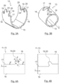
- the first crimping section 13 of the outer conductor contact element 11, which Fig. 3A in a pre-bent state, ie in a pre-assembly state, and in Fig, 3B in a final bent state, ie in a final assembly state, has a support area 15 for the cable 2, to the lateral ends of which a crimp flank 16 is connected.
- a crimp flank 16 is connected to the lateral ends of which a crimp flank 16 is connected.
- the cable 2 inserted into the outer conductor contact element 11 and pressed with the outer conductor contact element is not shown.
- Each crimp flank 16 has a side edge 17.
- the first crimping section 13 with its oppositely arranged crimping flanks 16 and associated oppositely arranged side edges 17 has a U-shaped cross-sectional profile.
- the side edges 17 of the two crimp flanks 16 touch each other along their entire longitudinal extent and form a sleeve-shaped cross-sectional profile of the first crimp section 13.
- the crimp connection in the first crimp section 13 has two crimp flanks 16, the side edges 17 of which are each shaped in such a way that in the final In the bent state of the crimp connection, the two crimp flanks each have interlocking regions 18.
- each finger-shaped recess 19 and each finger-shaped extension 20 each has at least one longitudinal extension section with a directional component in the longitudinal axis direction L of the outer conductor contact element 11 and with a directional component transverse to the longitudinal axis direction L of the outer conductor contact element 11.
- the side edges 17 of the two crimp flanks 16 nestle against one another along their entire longitudinal extension without an air gap in between and thus realize an air gap-free positive connection between the individual interlocked regions 18 of the two crimp flanks 17 in the longitudinal axis direction L and transverse to the longitudinal axis direction L of the outer conductor contact element 11.
- the optional second crimping section 14 of the outer conductor contact element 11 can have an equivalent shape in terms of the cross-sectional profile and an equivalent shape and equivalent arrangement of the finger-shaped recesses 19 and the finger-shaped extensions 20 on the side edges 17 of the two crimping flanks 16 to the first crimping section 13.
- the second crimping section 14 can also have a different shape of the side edges 17 of the two crimp flanks 16 to the first crimp section 13.
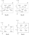
- FIG. 4A shows a side view of a crimp connection according to the invention in the final assembly state of the outer conductor contact element 11, in which a finger-shaped recess 19 is formed on the side edge 17 of one crimp flank 16 and a finger-shaped extension 20 is formed on the side edge of the other crimp flank 16, which is positively engaged in the longitudinal axis direction L and transversely to the longitudinal axis direction L in the finger-shaped recess 19 without forming an air gap in between.
- Fig. 4A are the edges 17 of the crimping tool that are formed during the crimping process when the two crimping edges 16 come into contact with each other.
- the impact forces F exerted by the crimp flank 16 shown above on the side edge 17 of the crimp flank 16 shown below can be seen, each of which is directed transversely to the longitudinal axis or longitudinal axis direction L of the outer conductor contact element 11.
- the impact force F which is exerted by the crimp flank 16 shown above on the side edge 17 in the region of the longitudinal extension of the finger-shaped extension 20 of the crimp flank 16 shown below, has a force component F S perpendicular to the side edge 17.
- the force component F S is transferred from the opposite side edge of the longitudinal extension of the finger-shaped extension 20 of the crimp flank 16 shown below to the opposite side edge of the finger-shaped recess 19 of the crimp flank 16 shown above. In this way, an air gap that may occur in the region of the undercut of the finger-shaped extension 20 and the finger-shaped recess 19 is advantageously closed.
- Fig. 4B is one to Fig. 4A equivalently shaped crimp connection consisting of a finger-shaped recess 19 and a finger-shaped extension 20. While in the form of the Fig. 4A the side edges 17 of the two crimp flanks 16 are aligned with one another in the longitudinal sections of the outer conductor contact element 2 adjacent to the finger-shaped recess 19 or the finger-shaped extension 20, the side edges 17 of the two crimp flanks 16 are arranged offset between the two adjacent longitudinal sections in the circumferential direction, ie transversely to the longitudinal axis direction L.
- a further embodiment of a crimp connection is shown in which a finger-shaped recess 19 and a finger-shaped extension 20 are formed on the side edge 17 of each of the two crimp flanks 16.
- the finger-shaped recess 19 merges directly into the finger-shaped extension 20 in such a way that the finger-shaped extensions 20 of the two crimp flanks 16 contact each other and thus clamp each other.
- the force component F S of the impact force F from the finger-shaped extension 20 of both crimp flanks 16 acts on the opposite finger-shaped extension 20 of the other crimp flank 19 and clamping in both directions is realized.
- an extension 21 and an associated recess 22 are formed on the side edges 17 of the two crimp flanks 16 in direct connection to a finger-shaped recess 19 and an associated finger-shaped extension 20, each of which has a longitudinal extension only transverse to the longitudinal axis direction L.
- the finger-shaped extension 20 on the side edge 17 of the Fig. 4E The crimp flank 16 shown above has a greater longitudinal extension due to the additional recess 22 than the finger-shaped extension 20 on the side edge 17 of the Fig. 4E crimp flank 16 shown below.
- the force component F S of the impact force F acting on the longer finger-shaped extension 20 and transmitted to the opposite shorter finger-shaped extension 20 is thus distributed over a larger section of the side edge 17 than for the shorter finger-shaped extension 20 (shown by the double arrows F S for the longer finger-shaped extension 20 in contrast to the single arrow F S for the shorter finger-shaped extension 20 in Fig. 4E ).
- an air gap possibly extending over a longer section of the side edge 17 between two oppositely formed finger-shaped extensions 20 can be closed.
- FIG. 4F to 4I Further embodiments of a crimp connection are shown in which several sequences, in particular two sequences, each consisting of a finger-shaped Recess 19 and a directly adjoining finger-shaped extension 20.
- the finger-shaped extensions 20 immediately follow one another axially and are each surrounded by the finger-shaped recesses 19, while on the side edge of the other crimp flank 16, the corresponding finger-shaped recesses 20 immediately follow one another axially and are each surrounded by the corresponding finger-shaped extensions 20.
- Such a symmetrical arrangement of the finger-shaped recesses 19 and the finger-shaped extensions 20 enables a more compact arrangement of the finger-shaped recesses 19 or the finger-shaped extensions 20 in the longitudinal axis direction L.
- the lateral distance a between the side edge 17 of the crimp flank 16 at the lateral ends of the two adjacent finger-shaped extensions 20 and the side edge of the crimp flank 16 in a trough-shaped formation 23 formed between the two adjacent finger-shaped extensions 20 can be of different sizes.
- a small distance a according to Fig. 4G enables an easy joining of the two crimp flanks 16 during the crimping process, while a large distance a according to Fig. 4H finger-shaped extensions 20 with a large longitudinal extension are realized, which better closes an air gap between two opposite and mutually clamping finger-shaped extensions 20 over a longer section of the side edges 17.
- the trough-shaped formation 23 formed on the side edge 17 of one crimp flank 16 snaps into place on the side edge 17 the other crimp flank 16 formed hill-shaped formation 24.
- finger-shaped recesses 19 and the associated finger-shaped extensions 20 of the previously explained embodiments of a crimp connection each have rounded lateral ends or rounded transitions to the adjacent longitudinal sections of the outer conductor contact element 11, the lateral ends of the finger-shaped recesses 19 and the associated finger-shaped extensions 20 in the Fig. 4J
- the crimp connection shown in the embodiment is linear and has angular transitions. The formation of air gaps between the opposing finger-shaped extensions 20 is further reduced with such an embodiment of a crimp connection.
- Fig. 4K finally represents an embodiment of a crimp connection in which, on the side edges 17 of the two crimp flanks 16, the two sequences of a finger-shaped recess 19 and an immediately following finger-shaped extension 20 are each surrounded by an extension 21 and an associated recess 22, each of which has a longitudinal extension only in a direction transverse to the longitudinal axis L.
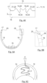
- side edges 17 of the two crimp flanks 16 of the outer conductor contact element 11 each have an inner bevel 25.
- the inner bevels 25 are preferably designed such that the side edges 17 of the crimp flanks 16 in the final assembly state, ie in the final formed state, according to Fig. 5C only contacted at the radially outer edge.
- the angle ⁇ between the outer surface 26 and the side edge 17 of the crimp flank 16 is smaller than 90°, preferably between 70° and 90°, due to the chamfer 25. This results in a preferred value of between 20° and 40° for the angle ⁇ between the two chamfered side edges 17. In this way, strands of the outer conductor 6 of the cable 2, which are located between the two side edges 17 of the crimp flanks 16 during the crimping process, are displaced radially inwards into the outer conductor contact element 11.
- FIG. 6A an outer conductor contact element 11 for a connector arrangement 1 is shown in a pre-assembled state, ie in a pre-bent state, which is manufactured according to a first variant of a manufacturing method for the connector arrangement 1.
- the outer conductor contact element 11 is angled for an angled connector 3. It has a first crimp section 13 for pressing with the outer conductor 6 of the cable 2, a contact section 12 angled thereto and a connecting section 27 located therebetween and aligned with the first crimp section 13.
- the first crimp section 13 and the connecting section 27 of the outer conductor contact element 11 are each pre-bent in a U-shape in order to insert the pre-assembled cable 2.
- the first crimping section 13 and the connecting section 27 are each sleeve-shaped.
- the outer conductor 6 of the cable 2 is pressed with the outer conductor contact element 11 in the first crimping section 13.
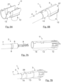
- Fig. 7A a pre-assembled cable 2 and an outer conductor contact element 11 separated therefrom are shown, which is manufactured according to a second variant of a manufacturing method for a connector arrangement 1.
- the outer conductor contact element 11 is in the exemplary representation of the Fig. 7A and 7B designed for a straight connector 3 and has a contacting section 12, a first crimping section 13 and additionally a second crimping section 14 for pressing with a cable sheath 7 of the cable 2.
- Fig. 7A a pre-assembled cable 2 and an outer conductor contact element 11 separated therefrom are shown, which is manufactured according to a second variant of a manufacturing method for a connector arrangement 1.
- the outer conductor contact element 11 is in the exemplary representation of the Fig. 7A and 7B designed for a straight connector 3 and has a contacting section 12, a first crimping section 13 and additionally a second crimping section 14 for pressing with a cable sheath 7 of the cable 2.
- the first crimp section 13 has a crimp connection according to the invention with finger-shaped recesses 19 and finger-shaped extension 20, the longitudinal extent of which each has a directional component in the longitudinal axis direction L and a directional component transverse to the longitudinal axis direction L.
- the second crimp section 14, has a conventional crimp connection according to the prior art.
- the outer conductor contact element 11, which is manufactured according to the second variant of a manufacturing method for a connector arrangement 1, is in the pre-assembled state according to Fig. 7A
- the pre-assembled cable 2 is inserted into the sleeve-shaped pre-formed outer conductor contact element 11. In the final assembly state according to Fig.
- the first crimp section 13 is pressed with the outer conductor 6 of the cable 2 and the second crimp section 14 with the cable sheath 7 of the cable 2.
- Fig. 7B It can be seen that the outer diameter of the first crimping section 13 is designed to be larger than the outer diameter of the second crimping section 14, so that the cable 2 with the support sleeve 8 fastened to the outer conductor 6 strikes the step 28 formed by the outer diameter jump and thus an improved axial fixation is formed between the cable 2 and the connector 3.
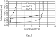
- Fig. 8 a comparison of the functional quality of several outer conductor crimp connections can be made, which were simulated for different crimping principles.
- the functional quality is determined by the relationship between the internal pressure caused by the crimp flanks of the support sleeve springing open and the resulting closing gap, i.e. the size of the air gap between the side edges of the two crimp flanks in the final assembled state of the outer conductor contact element:
- an outer conductor crimp connection according to the principle of EP 1 983 615 B1 (StdT 1 in Fig. 8 ) even a very low internal pressure leads to an opening of the crimp connection.
- an outer conductor crimp connection based on the principle of Fig.
Landscapes
- Engineering & Computer Science (AREA)
- Manufacturing & Machinery (AREA)
- Connections Effected By Soldering, Adhesion, Or Permanent Deformation (AREA)
Priority Applications (3)
| Application Number | Priority Date | Filing Date | Title |
|---|---|---|---|
| EP23177159.3A EP4475341A1 (fr) | 2023-06-05 | 2023-06-05 | Élément de contact de conducteur extérieur |
| CN202410689144.6A CN119093041A (zh) | 2023-06-05 | 2024-05-30 | 外部导体接触元件、电连接器组件及其生产方法 |
| US18/732,993 US20240405456A1 (en) | 2023-06-05 | 2024-06-04 | Outer Conductor Contact Element |
Applications Claiming Priority (1)
| Application Number | Priority Date | Filing Date | Title |
|---|---|---|---|
| EP23177159.3A EP4475341A1 (fr) | 2023-06-05 | 2023-06-05 | Élément de contact de conducteur extérieur |
Publications (1)
| Publication Number | Publication Date |
|---|---|
| EP4475341A1 true EP4475341A1 (fr) | 2024-12-11 |
Family
ID=86692879
Family Applications (1)
| Application Number | Title | Priority Date | Filing Date |
|---|---|---|---|
| EP23177159.3A Pending EP4475341A1 (fr) | 2023-06-05 | 2023-06-05 | Élément de contact de conducteur extérieur |
Country Status (3)
| Country | Link |
|---|---|
| US (1) | US20240405456A1 (fr) |
| EP (1) | EP4475341A1 (fr) |
| CN (1) | CN119093041A (fr) |
Citations (10)
| Publication number | Priority date | Publication date | Assignee | Title |
|---|---|---|---|---|
| EP1983615B1 (fr) | 2007-04-20 | 2012-08-01 | Delphi Technologies, Inc. | Connecteur électrique blindé et assemblage du câble et méthode de fabrication de celui-ci |
| EP3220483A1 (fr) * | 2016-03-17 | 2017-09-20 | TE Connectivity Germany GmbH | Dispositif de connexion électrique, procédé d'assemblage d'un câble électrique et câble coaxial électrique assemblé |
| EP3218965A1 (fr) * | 2014-11-12 | 2017-09-20 | TE Connectivity Corporation | Ensemble connecteur |
| US20180183190A1 (en) * | 2016-12-23 | 2018-06-28 | Te Connectivity Germany Gmbh | Electric Shielding Contact Device |
| EP3429029A1 (fr) * | 2017-07-15 | 2019-01-16 | Rosenberger Hochfrequenztechnik GmbH & Co. KG | Système de connecteur à fiches |
| EP3660986A1 (fr) * | 2018-11-28 | 2020-06-03 | Rosenberger Hochfrequenztechnik GmbH & Co. KG | Procédé et dispositif de surmoulage de câble destinés au montage d'un connecteur enfichable de câble |
| DE102020117663A1 (de) * | 2020-07-03 | 2022-01-05 | Rosenberger Hochfrequenztechnik Gmbh & Co. Kg | Außenleiterkontaktelement, Winkelsteckverbinder und Verfahren zur Herstellung eines Winkelsteckverbinders |
| US11462861B2 (en) * | 2018-02-16 | 2022-10-04 | Aptiv Technologies Limited | Electrical shielding member for a network connector |
| DE102022128954A1 (de) * | 2021-11-02 | 2023-05-04 | I-Pex Inc. | Anschluss und stecker |
| US20230155336A1 (en) * | 2021-11-16 | 2023-05-18 | TE Connectivity Services Gmbh | High Deformation and Retention Ferrule |
-
2023
- 2023-06-05 EP EP23177159.3A patent/EP4475341A1/fr active Pending
-
2024
- 2024-05-30 CN CN202410689144.6A patent/CN119093041A/zh active Pending
- 2024-06-04 US US18/732,993 patent/US20240405456A1/en active Pending
Patent Citations (10)
| Publication number | Priority date | Publication date | Assignee | Title |
|---|---|---|---|---|
| EP1983615B1 (fr) | 2007-04-20 | 2012-08-01 | Delphi Technologies, Inc. | Connecteur électrique blindé et assemblage du câble et méthode de fabrication de celui-ci |
| EP3218965A1 (fr) * | 2014-11-12 | 2017-09-20 | TE Connectivity Corporation | Ensemble connecteur |
| EP3220483A1 (fr) * | 2016-03-17 | 2017-09-20 | TE Connectivity Germany GmbH | Dispositif de connexion électrique, procédé d'assemblage d'un câble électrique et câble coaxial électrique assemblé |
| US20180183190A1 (en) * | 2016-12-23 | 2018-06-28 | Te Connectivity Germany Gmbh | Electric Shielding Contact Device |
| EP3429029A1 (fr) * | 2017-07-15 | 2019-01-16 | Rosenberger Hochfrequenztechnik GmbH & Co. KG | Système de connecteur à fiches |
| US11462861B2 (en) * | 2018-02-16 | 2022-10-04 | Aptiv Technologies Limited | Electrical shielding member for a network connector |
| EP3660986A1 (fr) * | 2018-11-28 | 2020-06-03 | Rosenberger Hochfrequenztechnik GmbH & Co. KG | Procédé et dispositif de surmoulage de câble destinés au montage d'un connecteur enfichable de câble |
| DE102020117663A1 (de) * | 2020-07-03 | 2022-01-05 | Rosenberger Hochfrequenztechnik Gmbh & Co. Kg | Außenleiterkontaktelement, Winkelsteckverbinder und Verfahren zur Herstellung eines Winkelsteckverbinders |
| DE102022128954A1 (de) * | 2021-11-02 | 2023-05-04 | I-Pex Inc. | Anschluss und stecker |
| US20230155336A1 (en) * | 2021-11-16 | 2023-05-18 | TE Connectivity Services Gmbh | High Deformation and Retention Ferrule |
Also Published As
| Publication number | Publication date |
|---|---|
| US20240405456A1 (en) | 2024-12-05 |
| CN119093041A (zh) | 2024-12-06 |
Similar Documents
| Publication | Publication Date | Title |
|---|---|---|
| DE102005016235B4 (de) | Draht-Pressklemmverfahren und Anschlussklemmen-Draht-Verbindung | |
| EP1455160A1 (fr) | Traversée métal-matériau de fixation et procédé de fabrication d'une tête d'initiateur avec traversée métal-matériau de fixation | |
| EP1133013B1 (fr) | Pièce de contact pour une connexion électrique ainsi que son procédé de fabrication | |
| DE3133154A1 (de) | Koaxial-abgriffverbinder | |
| EP3378128B1 (fr) | Arrangement avec un élément de contact et un câble électrique et méthode pour la production d'un tel arrangement | |
| EP3196981A1 (fr) | Connecteur transversal pour bornier | |
| WO1979000635A1 (fr) | Connecteur electrique et procede de fabrication | |
| DE2731001C3 (de) | Elektrische Steckkontaktbuchse | |
| EP1870961A1 (fr) | Raccordement de câbles | |
| DE20314580U1 (de) | Metall-Fixiermaterial-Durchführung | |
| EP2725659B1 (fr) | Manchon de câble coaxial | |
| DE3237159C1 (de) | Kontaktelement fuer elektrische Steckverbindungen und Verfahren zur Herstellung von derartigen Kontaktelementen | |
| EP2453526A1 (fr) | Dispositif de connexion et procédé de fabrication d'une connexion électrique conductrice | |
| DE2306136A1 (de) | Zuendkerzenklemmschraube und verfahren zu deren herstellung | |
| WO2017081194A1 (fr) | Contact à insérer et fabrication d'un contact à insérer | |
| WO2014015856A1 (fr) | Élément de contact | |
| EP4475341A1 (fr) | Élément de contact de conducteur extérieur | |
| WO2021160394A1 (fr) | Ensemble élément de contact pour partie fiche de connexion | |
| WO2022207444A1 (fr) | Élément de déplacement d'isolation, stator de machine électrique et procédé de fabrication de stator | |
| DE102015106820B4 (de) | Verfahren zur Herstellung einer elektrischen Steckverbinderbuchse | |
| DE102020119741A1 (de) | Kontaktelement und Verfahren zur Herstellung eines Kontaktelements | |
| DE3637626C2 (de) | Verfahren zum Festlegen eines Metallstifts innerhalb eines keramischen Isolierkörpers | |
| LU500419B1 (de) | Verbindungsanordnung mit Crimpverbindung und Verfahren zur Herstellung einer Verbindungsanordnung mit Crimpverbindung | |
| EP4354663B1 (fr) | Connecteur a sertir pour la connexion mecanique et electriquement conductrice d'un contact de connexion electrique a un conducteur electrique et connexion a sertir d'un contact de connexion electrique a un conducteur electrique | |
| DE102008062597B3 (de) | Verbindungselement mit mindestens einem elektrischen Steckkontakt und Verfahen zur Herstellung desselben |
Legal Events
| Date | Code | Title | Description |
|---|---|---|---|
| PUAI | Public reference made under article 153(3) epc to a published international application that has entered the european phase |
Free format text: ORIGINAL CODE: 0009012 |
|
| STAA | Information on the status of an ep patent application or granted ep patent |
Free format text: STATUS: THE APPLICATION HAS BEEN PUBLISHED |
|
| AK | Designated contracting states |
Kind code of ref document: A1 Designated state(s): AL AT BE BG CH CY CZ DE DK EE ES FI FR GB GR HR HU IE IS IT LI LT LU LV MC ME MK MT NL NO PL PT RO RS SE SI SK SM TR |
|
| STAA | Information on the status of an ep patent application or granted ep patent |
Free format text: STATUS: REQUEST FOR EXAMINATION WAS MADE |
|
| 17P | Request for examination filed |
Effective date: 20241219 |