EP4475355A1 - Support pour matériau filiforme - Google Patents
Support pour matériau filiforme Download PDFInfo
- Publication number
- EP4475355A1 EP4475355A1 EP24165282.5A EP24165282A EP4475355A1 EP 4475355 A1 EP4475355 A1 EP 4475355A1 EP 24165282 A EP24165282 A EP 24165282A EP 4475355 A1 EP4475355 A1 EP 4475355A1
- Authority
- EP
- European Patent Office
- Prior art keywords
- carrier
- material carrier
- line
- thread
- assembled state
- Prior art date
- Legal status (The legal status is an assumption and is not a legal conclusion. Google has not performed a legal analysis and makes no representation as to the accuracy of the status listed.)
- Pending
Links
Images


Classifications
-
- H—ELECTRICITY
- H01—ELECTRIC ELEMENTS
- H01R—ELECTRICALLY-CONDUCTIVE CONNECTIONS; STRUCTURAL ASSOCIATIONS OF A PLURALITY OF MUTUALLY-INSULATED ELECTRICAL CONNECTING ELEMENTS; COUPLING DEVICES; CURRENT COLLECTORS
- H01R43/00—Apparatus or processes specially adapted for manufacturing, assembling, maintaining, or repairing of line connectors or current collectors or for joining electric conductors
- H01R43/28—Apparatus or processes specially adapted for manufacturing, assembling, maintaining, or repairing of line connectors or current collectors or for joining electric conductors for wire processing before connecting to contact members, not provided for in groups H01R43/02 - H01R43/26
-
- B—PERFORMING OPERATIONS; TRANSPORTING
- B65—CONVEYING; PACKING; STORING; HANDLING THIN OR FILAMENTARY MATERIAL
- B65H—HANDLING THIN OR FILAMENTARY MATERIAL, e.g. SHEETS, WEBS, CABLES
- B65H51/00—Forwarding filamentary material
-
- B—PERFORMING OPERATIONS; TRANSPORTING
- B65—CONVEYING; PACKING; STORING; HANDLING THIN OR FILAMENTARY MATERIAL
- B65H—HANDLING THIN OR FILAMENTARY MATERIAL, e.g. SHEETS, WEBS, CABLES
- B65H2701/00—Handled material; Storage means
- B65H2701/30—Handled filamentary material
- B65H2701/32—Optical fibres or optical cables
-
- B—PERFORMING OPERATIONS; TRANSPORTING
- B65—CONVEYING; PACKING; STORING; HANDLING THIN OR FILAMENTARY MATERIAL
- B65H—HANDLING THIN OR FILAMENTARY MATERIAL, e.g. SHEETS, WEBS, CABLES
- B65H2701/00—Handled material; Storage means
- B65H2701/30—Handled filamentary material
- B65H2701/34—Handled filamentary material electric cords or electric power cables
Definitions
- the invention relates to a material carrier for a thread-like material, in particular an electrical or optical line.
- cables or lines are regularly clamped into so-called product carriers for processing or for transport between processing stations and transported using a transport device.
- the product carriers are moved along predetermined transport paths. If a product carrier cannot reach a subsequent processing station, the cable or line must be removed and fed to the subsequent processing station by another route. In the process, the line must at least be identified again at the subsequent processing station, possibly introduced into a new transport system and realigned.
- the publication US 2023/0041384 A1 relates to a cable holding device that can be useful in cable processing processes.
- the cable holding device comprises a pivotable or rotatable clamping device in one end section for selectively clamping the cable.
- a pivotable clamp or a clamp end is connected to the cable by a pin or a shoulder-shaped fastening element that passes through an opening formed in the clamp end and a corresponding coaxial opening in the end section, rotatably attached to the end section.
- the devices from the state of the art have at least the disadvantages that they often cannot be moved freely with the cable, inserting the cable is difficult or requires manual work steps, and/or the structure of the device is complex and unsuitable for robust use in a factory hall.
- inserting a cable into a goods carrier in the state of the art is done manually. Manual insertion is time-consuming and error-prone.
- Grippers or similar devices are necessary for further movement.
- the grippers only fix a cable imprecisely. Further directed movement or processing then requires the cable to be fixed precisely again. And finally, future cables will be more elastic, making handling with goods carriers or grippers from the state of the art more difficult.
- a material carrier for a thread-like material comprising at least a first and a separate second carrier element, wherein the first and the second carrier element form the material carrier in the assembled state, and at least one guide on the first and/or the second carrier element, which in the assembled state extends along a first direction through the material carrier and in which the thread-like material can be arranged, whereby the material carrier can be attached to the thread-like material and moved with it regardless of direction.
- This material carrier has a very simple and at the same time very robust structure.
- This structure makes handling this material carrier very simple and user-friendly. Handling includes not only handling the assembled material carrier, but also handling the individual components.
- This material carrier deliberately dispenses with movable mechanical elements such as hinges in order to keep wear and tear as low as possible. This dispensation increases the service life of this material carrier.
- the simple structure enables fully automated use or assembly of the material carrier. Due to its compact external dimensions and the attachment of the material carrier to the thread-like material or the line, this material carrier can remain on the line throughout an entire (assembly) process. The line is easy to grip, align, feed to various processing stations and identify at any time using this material carrier.
- This material carrier is reusable, and individual carrier elements can be easily replaced if they wear out.
- the present material carrier provides stability in its area, particularly to flexible cables or very thin cables, so that the cables can be well aligned and processed.
- the at least two carrier elements can be releasably attached to one another in the assembled state using holding forces. Holding forces can include magnetic forces, adhesive forces, static friction forces, and/or mechanical holding forces, such as locking, clicking, elastic deformation, interlocking and the like.
- Holding forces can include magnetic forces, adhesive forces, static friction forces, and/or mechanical holding forces, such as locking, clicking, elastic deformation, interlocking and the like.
- the feature that the second carrier element is provided separately from the first carrier element means in particular that the second carrier element is only attached to the first carrier element after a thread-like material has been arranged (between the first and second carrier elements).
- the separate provision of the carrier elements enables and/or simplifies automated handling of the material carrier.
- the first and second carrier elements are detachably attached to one another via a securing element.
- the securing element is preferably a separate component.
- the securing element can preferably be arranged manually or automatically on the first and second carrier elements. If the material carrier is made up of more than two carrier elements, the securing element secures all of the carrier elements to one another.
- the securing element has the task of attaching the carrier elements that form the material carrier to one another, whereby the securing element can be designed independently of the carrier elements and vice versa. This enables a large number of design options, so that the material carrier as a whole can be very well adapted to products and processes.
- the first and second carrier elements have at least one first fixing means.
- the first fixing means enables the first and second carrier elements to be oriented relative to one another.
- the first fixing means prevents the first and second carrier elements from being displaced relative to one another along the central axis.
- the first and second carrier elements have at least one second fixing means, wherein the second fixing means is designed to be complementary to the first fixing means.
- the first and second fixing means engage with one another in the assembled state.
- the second complementary fixing means increases the reliability of the arrangement of the first and second carrier elements to one another.
- the first and the second carrier element each have an identification feature or a partial identification feature which, when the material carrier is assembled, results in a common identification feature.
- a (partial) identification feature comprises in particular an optically or electronically recognizable feature, such as an RFID tag or QR code, with which a carrier element or material carrier can be clearly recognized.
- each carrier element has an identification feature
- conclusions can be drawn about the use of the carrier element via the identification feature, for example its wear after a number of inserts.
- the identification feature only becomes valid when the material carrier is assembled and can clearly identify the enclosed line. The latter case would have the advantage that the number of identification features can be kept smaller, and thus, for example, a QR code with fewer elements would be sufficient.
- the first and second carrier elements each comprise a front region which has a bevelled surface, wherein the front regions preferably form a cone shape when the tool carrier is assembled.
- the bevelled surfaces or the cone shape enable automatic centered alignment of the material carrier when inserted into a corresponding opening at a processing station.
- the cone shape is radially symmetrical, so that the centered alignment can take place regardless of the angle of rotation of the line.
- the first and second carrier elements each have a positioning, wherein the positionings form a common positioning in the assembled state.
- the common positioning can ensure rapid and secure positioning of the material carrier relative to a gripping device or a processing station.
- the common positioning can also serve to provide a fixed second length to the tip of the free end.
- the material carrier is designed in such a way that it can accommodate the free end of the thread-like material.
- the free end can be arranged within the material carrier simply by moving the material carrier relative to the line or vice versa. The arrangement of the free end within the material carrier protects the free end from unwanted damage.
- the first and second carrier elements are constructed identically.
- the identical carrier elements make the construction of the material carrier structurally very simple and user-friendly.
- any (two) carrier elements can be combined with one another to form a material carrier.
- the first and second carrier elements are made of plastic.
- the plastic makes the material carrier light but still robust.
- Plastic is an inexpensive material and can easily be formed into a material carrier using a suitable process, such as an injection molding process. When using plastic, as opposed to a harder material such as metal, the risk of damaging a cable is at least reduced.
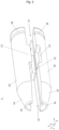
- Fig. 1 shows an embodiment of a material carrier 1 for a thread-like material 3 in the assembled state with an inserted material or an inserted line 3.
- the material carrier 1 shown has at least a first and a separate second carrier element 10, 10'.
- the first and the second carrier element 10, 10' form the material carrier 1 in the assembled state.
- the first and second carrier elements 10, 10' are detachably attached to one another via a securing element 7.
- the first and second carrier elements 10, 10' to one another via holding forces.
- the inner surfaces 19 of the first and second carrier elements 10, 10' can be magnetically designed.
- the first and second carrier elements 10, 10' can be attached to one another via other (chemical or mechanical) holding forces.
- Fig. 2 shows an embodiment of the first carrier element 10.
- the first and second carrier elements 10, 10' are constructed identically.
- the illustrated first (and second) carrier element 10 (10') has at least one first fixing means 12 (12').
- the first fixing means 12 is formed as a projection.
- the first and second carrier elements 10, 10' can be visually and haptically aligned with one another via the first fixing means 12.
- the illustrated first (and second) carrier element 10 (10') has at least one second fixing means 13.
- the second fixing means 13 is designed to be complementary to the first fixing means 12.
- the second fixing means 13 is a recess into which the projection of the first fixing means 12 can be inserted.
- first and second carrier elements 10, 10' can each have an identification feature.
- the identification feature comprises an RFID tag or a QR code.
- alternative identification features can be used to uniquely identify a carrier element. Optically or electronically readable identification features are particularly suitable.
- the first and second carrier elements 10, 10' each have a partial identification feature, which result in a common identification feature when the material carrier is assembled.
- each carrier element 10, 10' could have part of a QR code, which is arranged on the carrier elements in such a way that it results in a complete QR code when assembled. This QR Code, a line 3 would be uniquely identifiable as long as it is held in the assembled material carrier 1.
- first and second carrier elements 10, 10' each comprise a front region 14, 14'.
- the front region 14, 14' each ends with a front end 16, 16'.
- a first length L1 can be defined between the front ends 16, 16' and the tip of the free end 5 of the line 3.
- the first length L1 indicates how far the free end 5 protrudes forwards over the material carrier 1 along the first direction X.
- the illustrated front regions 14, 14' each have a bevelled surface.
- the front regions 14, 14' form a cone shape when the material carrier 1 is assembled. The cone shape is particularly suitable for self-centering alignment of the material carrier 1 at a processing station.
- the first and second carrier elements 10, 10' each have a positioning 18, 18', wherein the positionings 18, 18' form a common positioning in the assembled state.
- the common positioning comprises a circumferential recess.
- the material carrier 1 can be clearly gripped or aligned via the recess.
- a second length L2 from the recess to the tip of the free end 5 of the line 3, can be determined via the common recess.
- the line 3 can be precisely aligned via the second length L2, for example at a processing station.
- the illustrated material carrier 1 further comprises at least one guide 11 on the first and/or second carrier element 10, 10' (see Fig. 2 ).
- the guide 11 runs in the assembled state along a central axis M in a first direction X through the material carrier 1.
- the thread-like material or the line 3 shown can be arranged within the guide 11.
- the line 3 can be arranged with its free end 5 completely in the guide 11. This requirement can arise, for example, to protect the free end 5 during (longer) transport of the line 3.
- the guide 11 forms a first opening 15 for the line 3.
- the guide 11 forms a second opening 17.
- the material carrier 1 is attached to the thread-like material or the line 3 and can be moved with it regardless of direction. Due to the elongated and compact shape of the material carrier 1 along the line 3, the material carrier 1 can remain on the line 3 without being exposed to the risk of severe damage. Due to the permanent attachment (during cable assembly) of the material carrier 1 to the line 3, the material carrier 1 stabilizes, for example, thin or very elastic lines 3 so that they can be gripped and processed more easily. In particular, the thread-like material or the line 3 is held in the guide 11 by frictional engagement. And a line 3 can be made available to any processing station regardless of direction via the material carrier 1.
- the first and second carrier elements 10, 10', and in particular the entire material carrier 1, are preferably made of plastic.
- a material carrier 1 For the use of a material carrier 1 shown, at least one material carrier 1 is attached to each line 3 to be processed/assembled.
- the attachment can be automated, for example after cutting or cutting the line 3 to length.
- the material carrier 1 is attached to the line 3 at the beginning of a line assembly and only at the end, for Example: shortly before the packaging of the line 3, it is removed from the line 3 again. Because the material carrier 1 remains on the line 3 the whole time, the line 3 can be easily and precisely fixed via the material carrier 1, processed at process stations and always identified.
- the material carrier 1 is formed from two identical plastic carrier elements 10, 10'.
- a first carrier element 10 is provided so that the guide 11 is clearly visible as a recess.
- a line 3 is then arranged in the guide 11.
- the size of the guide 11 or recess is adapted to the line 3 to be held.
- Various carrier elements 10 with different guide sizes can be present. A distinction can be made, for example, by means of a color marking.
- the line 3 should lie properly in the guide 11 so that the line 3 is held in the material carrier 1 by friction in the assembled state.
- the length L1 can be selected appropriately when the line 1 is inserted.
- a securing element 7 in the form of a ring is pushed onto the material carrier 1. This step can also be carried out automatically.
- the securing element 7 can be implemented differently, for example in the form of a bayonet lock, a tensioning strap, a buckle, a winding, etc.
- the material carrier 1 is then attached to the line 3 and can be moved with it in any direction.
- a line 3 is easier to grip on the material carrier 1 and has a defined position.
- the Material carrier 1 makes it possible to process the line 3 on the fly, since the material carrier 1 can be guided easily and in any direction.
- an (unassembled) free end 5 of the line 3 can be protected by pulling it into the material carrier 1.
- the securing element 7 may have to be briefly released in order to reduce or eliminate the frictional connection.
- the material carrier 1 shown can be easily dismantled by removing the securing element 7 and separating the first and second carrier elements 10, 10' from one another.
- the (inner) diameter of the securing element 7 is usually larger than a connector that has been assembled on the free end 5 of the line 3. Therefore, the securing element 7 in the illustrated embodiment of a ring can simply be pulled off over the free end 5 of the line 3.
- the two support elements 10, 10' can then be separated from each other transversely to the first direction X, in particular along the second or third direction Y, Z, independently of the assembly of the cable 3.
- Each material carrier 1 or the individual components can be reused.
- the identical carrier elements 10, 10' can be kept in a storage unit for later use.
- any two carrier elements 10, 10' can then be removed from the storage unit and assembled to form a material carrier 1.
Landscapes
- Engineering & Computer Science (AREA)
- Manufacturing & Machinery (AREA)
- Package Frames And Binding Bands (AREA)
- Physical Vapour Deposition (AREA)
- Manufacturing Of Electrical Connectors (AREA)
Applications Claiming Priority (1)
| Application Number | Priority Date | Filing Date | Title |
|---|---|---|---|
| DE102023115127.4A DE102023115127A1 (de) | 2023-06-09 | 2023-06-09 | Werkstoffträger für einen fadenförmigen werkstoff |
Publications (1)
| Publication Number | Publication Date |
|---|---|
| EP4475355A1 true EP4475355A1 (fr) | 2024-12-11 |
Family
ID=90417565
Family Applications (1)
| Application Number | Title | Priority Date | Filing Date |
|---|---|---|---|
| EP24165282.5A Pending EP4475355A1 (fr) | 2023-06-09 | 2024-03-21 | Support pour matériau filiforme |
Country Status (4)
| Country | Link |
|---|---|
| EP (1) | EP4475355A1 (fr) |
| CN (1) | CN119100191A (fr) |
| DE (1) | DE102023115127A1 (fr) |
| MX (1) | MX2024004686A (fr) |
Citations (5)
| Publication number | Priority date | Publication date | Assignee | Title |
|---|---|---|---|---|
| US3716650A (en) * | 1970-05-29 | 1973-02-13 | Mecquenem R De | Clamp with resilient gripping unit for use with overhead conductor spacers and a spacer including the same |
| US6135398A (en) * | 1997-12-19 | 2000-10-24 | Alcoa Fujikura Limited | Trunion clamp for optical fiber |
| DE102020125277A1 (de) * | 2020-09-28 | 2022-03-31 | HEPL Beteiligungsgesellschaft mbH | Vorrichtung zum Halten flexibler Übertragungsmittel |
| US20230041384A1 (en) | 2021-08-06 | 2023-02-09 | TE Connectivity Services Gmbh | Modular Cable Holding System and Device |
| US20230089874A1 (en) * | 2021-09-20 | 2023-03-23 | Airbus Canada Limited Partnership | Aircraft line or harness fastening system |
Family Cites Families (1)
| Publication number | Priority date | Publication date | Assignee | Title |
|---|---|---|---|---|
| US20210351579A1 (en) * | 2018-08-21 | 2021-11-11 | Pmi Industries, Inc. | Wind hang off |
-
2023
- 2023-06-09 DE DE102023115127.4A patent/DE102023115127A1/de active Pending
-
2024
- 2024-03-21 EP EP24165282.5A patent/EP4475355A1/fr active Pending
- 2024-04-17 MX MX2024004686A patent/MX2024004686A/es unknown
- 2024-05-24 CN CN202410656328.2A patent/CN119100191A/zh active Pending
Patent Citations (5)
| Publication number | Priority date | Publication date | Assignee | Title |
|---|---|---|---|---|
| US3716650A (en) * | 1970-05-29 | 1973-02-13 | Mecquenem R De | Clamp with resilient gripping unit for use with overhead conductor spacers and a spacer including the same |
| US6135398A (en) * | 1997-12-19 | 2000-10-24 | Alcoa Fujikura Limited | Trunion clamp for optical fiber |
| DE102020125277A1 (de) * | 2020-09-28 | 2022-03-31 | HEPL Beteiligungsgesellschaft mbH | Vorrichtung zum Halten flexibler Übertragungsmittel |
| US20230041384A1 (en) | 2021-08-06 | 2023-02-09 | TE Connectivity Services Gmbh | Modular Cable Holding System and Device |
| US20230089874A1 (en) * | 2021-09-20 | 2023-03-23 | Airbus Canada Limited Partnership | Aircraft line or harness fastening system |
Also Published As
| Publication number | Publication date |
|---|---|
| MX2024004686A (es) | 2025-01-09 |
| CN119100191A (zh) | 2024-12-10 |
| DE102023115127A1 (de) | 2024-12-12 |
Similar Documents
| Publication | Publication Date | Title |
|---|---|---|
| DE19513936B4 (de) | Stecker | |
| DE69506340T2 (de) | Deckel-Orientierungsvorrichtung | |
| DE102016121160A1 (de) | Lötanlage | |
| EP3207600B1 (fr) | Séquence de câbles pour le câblage d'un circuit électrique, procédé de fabrication et utilisation | |
| EP4475355A1 (fr) | Support pour matériau filiforme | |
| EP1215153A2 (fr) | Installation pour l'enroulement optimal et automatique de longueurs de tuyau | |
| DE68902278T2 (de) | Befestigung eines buendels von laenglichen gegenstaenden oder eines nichtkreisfoermigen laenglichen gegenstandes auf einer unterlage. | |
| DE69107388T2 (de) | Apparat und Verfahren zum Aufspulen eines Fadens. | |
| DE102018129917A1 (de) | Verfahren zum maschinellen Vorcrimpen von Stents, insbesondere medikamentenbeschichteten Stents | |
| DE102015103444B4 (de) | Kabelsequenz für eine Verdrahtung einer elektrischen Schaltung, Verfahren zum Herstellen sowie Verwendung | |
| DE102016101173B4 (de) | Wechseleinrichtung mit fangvorrichtung | |
| DE3310973A1 (de) | Steckerteil fuer loesbare steckverbindungen von lichtwellenleitern, verfahren zu dessen herstellung und vorrichtung zur ausfuehrung des verfahrens | |
| DE2928916C3 (de) | Einrichtung zum Befestigen des Magnetbandes an den Spulen in einer Magnetbandkassette | |
| DE102019003152A1 (de) | Verfahren und Vorrichtung zur Herstellung eines Verbundfadens | |
| DE102019134093A1 (de) | Wechselstation zum Ersetzen eines verbrauchten Arbeitsmittels durch ein unverbrauchtes Arbeitsmittel | |
| EP0741974A1 (fr) | Dispositif de rubans d'attache | |
| DE60107762T2 (de) | Spanndorn mit einklappbarem Spannglied | |
| DE202017102476U1 (de) | Vorrichtung zum Positionieren von freien Enden elektrischer Leitungen sowie damit ausgestattete Kabelverarbeitungsmaschine | |
| DE102016110781B4 (de) | Vorrichtung und Verfahren zum Zwischenlagern von Leitungen | |
| EP3348346B1 (fr) | Procédé et dispositif de production de tuyaux flexibles de raccordement | |
| DE102020128437A1 (de) | Vorrichtung und Verfahren zur Montage eines Steckverbinders | |
| DE102020115937A1 (de) | Roboterhand und Roboter | |
| DE3818896C2 (fr) | ||
| DE102019004674A1 (de) | Fadenabsaugvorrichtung | |
| DE102021113534B3 (de) | Werkstückträger für die Aufnahme eines zwei Strangenden aufweisenden Leitungsstranges zur automatisierten Verarbeitung |
Legal Events
| Date | Code | Title | Description |
|---|---|---|---|
| PUAI | Public reference made under article 153(3) epc to a published international application that has entered the european phase |
Free format text: ORIGINAL CODE: 0009012 |
|
| STAA | Information on the status of an ep patent application or granted ep patent |
Free format text: STATUS: THE APPLICATION HAS BEEN PUBLISHED |
|
| AK | Designated contracting states |
Kind code of ref document: A1 Designated state(s): AL AT BE BG CH CY CZ DE DK EE ES FI FR GB GR HR HU IE IS IT LI LT LU LV MC ME MK MT NL NO PL PT RO RS SE SI SK SM TR |
|
| STAA | Information on the status of an ep patent application or granted ep patent |
Free format text: STATUS: REQUEST FOR EXAMINATION WAS MADE |
|
| 17P | Request for examination filed |
Effective date: 20250602 |
|
| RAP3 | Party data changed (applicant data changed or rights of an application transferred) |
Owner name: MD ELEKTRONIK GMBH |
|
| RAP3 | Party data changed (applicant data changed or rights of an application transferred) |
Owner name: MD ELEKTRONIK GMBH |
|
| GRAP | Despatch of communication of intention to grant a patent |
Free format text: ORIGINAL CODE: EPIDOSNIGR1 |
|
| STAA | Information on the status of an ep patent application or granted ep patent |
Free format text: STATUS: GRANT OF PATENT IS INTENDED |
|
| RIC1 | Information provided on ipc code assigned before grant |
Ipc: H01R 43/28 20060101AFI20260319BHEP |