EP4475384A1 - Elektrisches arbeitsfahrzeug - Google Patents
Elektrisches arbeitsfahrzeug Download PDFInfo
- Publication number
- EP4475384A1 EP4475384A1 EP22924931.3A EP22924931A EP4475384A1 EP 4475384 A1 EP4475384 A1 EP 4475384A1 EP 22924931 A EP22924931 A EP 22924931A EP 4475384 A1 EP4475384 A1 EP 4475384A1
- Authority
- EP
- European Patent Office
- Prior art keywords
- charging
- battery
- ambient temperature
- control device
- time
- Prior art date
- Legal status (The legal status is an assumption and is not a legal conclusion. Google has not performed a legal analysis and makes no representation as to the accuracy of the status listed.)
- Pending
Links
Images






Classifications
-
- B—PERFORMING OPERATIONS; TRANSPORTING
- B60—VEHICLES IN GENERAL
- B60L—PROPULSION OF ELECTRICALLY-PROPELLED VEHICLES; SUPPLYING ELECTRIC POWER FOR AUXILIARY EQUIPMENT OF ELECTRICALLY-PROPELLED VEHICLES; ELECTRODYNAMIC BRAKE SYSTEMS FOR VEHICLES IN GENERAL; MAGNETIC SUSPENSION OR LEVITATION FOR VEHICLES; MONITORING OPERATING VARIABLES OF ELECTRICALLY-PROPELLED VEHICLES; ELECTRIC SAFETY DEVICES FOR ELECTRICALLY-PROPELLED VEHICLES
- B60L53/00—Methods of charging batteries, specially adapted for electric vehicles; Charging stations or on-board charging equipment therefor; Exchange of energy storage elements in electric vehicles
- B60L53/10—Methods of charging batteries, specially adapted for electric vehicles; Charging stations or on-board charging equipment therefor; Exchange of energy storage elements in electric vehicles characterised by the energy transfer between the charging station and the vehicle
- B60L53/14—Conductive energy transfer
-
- B—PERFORMING OPERATIONS; TRANSPORTING
- B60—VEHICLES IN GENERAL
- B60L—PROPULSION OF ELECTRICALLY-PROPELLED VEHICLES; SUPPLYING ELECTRIC POWER FOR AUXILIARY EQUIPMENT OF ELECTRICALLY-PROPELLED VEHICLES; ELECTRODYNAMIC BRAKE SYSTEMS FOR VEHICLES IN GENERAL; MAGNETIC SUSPENSION OR LEVITATION FOR VEHICLES; MONITORING OPERATING VARIABLES OF ELECTRICALLY-PROPELLED VEHICLES; ELECTRIC SAFETY DEVICES FOR ELECTRICALLY-PROPELLED VEHICLES
- B60L50/00—Electric propulsion with power supplied within the vehicle
- B60L50/50—Electric propulsion with power supplied within the vehicle using propulsion power supplied by batteries or fuel cells
- B60L50/60—Electric propulsion with power supplied within the vehicle using propulsion power supplied by batteries or fuel cells using power supplied by batteries
-
- B—PERFORMING OPERATIONS; TRANSPORTING
- B60—VEHICLES IN GENERAL
- B60L—PROPULSION OF ELECTRICALLY-PROPELLED VEHICLES; SUPPLYING ELECTRIC POWER FOR AUXILIARY EQUIPMENT OF ELECTRICALLY-PROPELLED VEHICLES; ELECTRODYNAMIC BRAKE SYSTEMS FOR VEHICLES IN GENERAL; MAGNETIC SUSPENSION OR LEVITATION FOR VEHICLES; MONITORING OPERATING VARIABLES OF ELECTRICALLY-PROPELLED VEHICLES; ELECTRIC SAFETY DEVICES FOR ELECTRICALLY-PROPELLED VEHICLES
- B60L53/00—Methods of charging batteries, specially adapted for electric vehicles; Charging stations or on-board charging equipment therefor; Exchange of energy storage elements in electric vehicles
- B60L53/60—Monitoring or controlling charging stations
- B60L53/62—Monitoring or controlling charging stations in response to charging parameters, e.g. current, voltage or electrical charge
-
- B—PERFORMING OPERATIONS; TRANSPORTING
- B60—VEHICLES IN GENERAL
- B60L—PROPULSION OF ELECTRICALLY-PROPELLED VEHICLES; SUPPLYING ELECTRIC POWER FOR AUXILIARY EQUIPMENT OF ELECTRICALLY-PROPELLED VEHICLES; ELECTRODYNAMIC BRAKE SYSTEMS FOR VEHICLES IN GENERAL; MAGNETIC SUSPENSION OR LEVITATION FOR VEHICLES; MONITORING OPERATING VARIABLES OF ELECTRICALLY-PROPELLED VEHICLES; ELECTRIC SAFETY DEVICES FOR ELECTRICALLY-PROPELLED VEHICLES
- B60L58/00—Methods or circuit arrangements for monitoring or controlling batteries or fuel cells, specially adapted for electric vehicles
- B60L58/10—Methods or circuit arrangements for monitoring or controlling batteries or fuel cells, specially adapted for electric vehicles for monitoring or controlling batteries
-
- B—PERFORMING OPERATIONS; TRANSPORTING
- B60—VEHICLES IN GENERAL
- B60L—PROPULSION OF ELECTRICALLY-PROPELLED VEHICLES; SUPPLYING ELECTRIC POWER FOR AUXILIARY EQUIPMENT OF ELECTRICALLY-PROPELLED VEHICLES; ELECTRODYNAMIC BRAKE SYSTEMS FOR VEHICLES IN GENERAL; MAGNETIC SUSPENSION OR LEVITATION FOR VEHICLES; MONITORING OPERATING VARIABLES OF ELECTRICALLY-PROPELLED VEHICLES; ELECTRIC SAFETY DEVICES FOR ELECTRICALLY-PROPELLED VEHICLES
- B60L58/00—Methods or circuit arrangements for monitoring or controlling batteries or fuel cells, specially adapted for electric vehicles
- B60L58/10—Methods or circuit arrangements for monitoring or controlling batteries or fuel cells, specially adapted for electric vehicles for monitoring or controlling batteries
- B60L58/12—Methods or circuit arrangements for monitoring or controlling batteries or fuel cells, specially adapted for electric vehicles for monitoring or controlling batteries responding to state of charge [SoC]
-
- B—PERFORMING OPERATIONS; TRANSPORTING
- B60—VEHICLES IN GENERAL
- B60L—PROPULSION OF ELECTRICALLY-PROPELLED VEHICLES; SUPPLYING ELECTRIC POWER FOR AUXILIARY EQUIPMENT OF ELECTRICALLY-PROPELLED VEHICLES; ELECTRODYNAMIC BRAKE SYSTEMS FOR VEHICLES IN GENERAL; MAGNETIC SUSPENSION OR LEVITATION FOR VEHICLES; MONITORING OPERATING VARIABLES OF ELECTRICALLY-PROPELLED VEHICLES; ELECTRIC SAFETY DEVICES FOR ELECTRICALLY-PROPELLED VEHICLES
- B60L58/00—Methods or circuit arrangements for monitoring or controlling batteries or fuel cells, specially adapted for electric vehicles
- B60L58/10—Methods or circuit arrangements for monitoring or controlling batteries or fuel cells, specially adapted for electric vehicles for monitoring or controlling batteries
- B60L58/24—Methods or circuit arrangements for monitoring or controlling batteries or fuel cells, specially adapted for electric vehicles for monitoring or controlling batteries for controlling the temperature of batteries
- B60L58/25—Methods or circuit arrangements for monitoring or controlling batteries or fuel cells, specially adapted for electric vehicles for monitoring or controlling batteries for controlling the temperature of batteries by controlling the electric load
-
- B—PERFORMING OPERATIONS; TRANSPORTING
- B60—VEHICLES IN GENERAL
- B60L—PROPULSION OF ELECTRICALLY-PROPELLED VEHICLES; SUPPLYING ELECTRIC POWER FOR AUXILIARY EQUIPMENT OF ELECTRICALLY-PROPELLED VEHICLES; ELECTRODYNAMIC BRAKE SYSTEMS FOR VEHICLES IN GENERAL; MAGNETIC SUSPENSION OR LEVITATION FOR VEHICLES; MONITORING OPERATING VARIABLES OF ELECTRICALLY-PROPELLED VEHICLES; ELECTRIC SAFETY DEVICES FOR ELECTRICALLY-PROPELLED VEHICLES
- B60L58/00—Methods or circuit arrangements for monitoring or controlling batteries or fuel cells, specially adapted for electric vehicles
- B60L58/10—Methods or circuit arrangements for monitoring or controlling batteries or fuel cells, specially adapted for electric vehicles for monitoring or controlling batteries
- B60L58/24—Methods or circuit arrangements for monitoring or controlling batteries or fuel cells, specially adapted for electric vehicles for monitoring or controlling batteries for controlling the temperature of batteries
- B60L58/26—Methods or circuit arrangements for monitoring or controlling batteries or fuel cells, specially adapted for electric vehicles for monitoring or controlling batteries for controlling the temperature of batteries by cooling
-
- B—PERFORMING OPERATIONS; TRANSPORTING
- B60—VEHICLES IN GENERAL
- B60L—PROPULSION OF ELECTRICALLY-PROPELLED VEHICLES; SUPPLYING ELECTRIC POWER FOR AUXILIARY EQUIPMENT OF ELECTRICALLY-PROPELLED VEHICLES; ELECTRODYNAMIC BRAKE SYSTEMS FOR VEHICLES IN GENERAL; MAGNETIC SUSPENSION OR LEVITATION FOR VEHICLES; MONITORING OPERATING VARIABLES OF ELECTRICALLY-PROPELLED VEHICLES; ELECTRIC SAFETY DEVICES FOR ELECTRICALLY-PROPELLED VEHICLES
- B60L58/00—Methods or circuit arrangements for monitoring or controlling batteries or fuel cells, specially adapted for electric vehicles
- B60L58/10—Methods or circuit arrangements for monitoring or controlling batteries or fuel cells, specially adapted for electric vehicles for monitoring or controlling batteries
- B60L58/24—Methods or circuit arrangements for monitoring or controlling batteries or fuel cells, specially adapted for electric vehicles for monitoring or controlling batteries for controlling the temperature of batteries
- B60L58/27—Methods or circuit arrangements for monitoring or controlling batteries or fuel cells, specially adapted for electric vehicles for monitoring or controlling batteries for controlling the temperature of batteries by heating
-
- H—ELECTRICITY
- H01—ELECTRIC ELEMENTS
- H01M—PROCESSES OR MEANS, e.g. BATTERIES, FOR THE DIRECT CONVERSION OF CHEMICAL ENERGY INTO ELECTRICAL ENERGY
- H01M10/00—Secondary cells; Manufacture thereof
- H01M10/42—Methods or arrangements for servicing or maintenance of secondary cells or secondary half-cells
- H01M10/44—Methods for charging or discharging
-
- H—ELECTRICITY
- H01—ELECTRIC ELEMENTS
- H01M—PROCESSES OR MEANS, e.g. BATTERIES, FOR THE DIRECT CONVERSION OF CHEMICAL ENERGY INTO ELECTRICAL ENERGY
- H01M10/00—Secondary cells; Manufacture thereof
- H01M10/42—Methods or arrangements for servicing or maintenance of secondary cells or secondary half-cells
- H01M10/48—Accumulators combined with arrangements for measuring, testing or indicating the condition of cells, e.g. the level or density of the electrolyte
-
- H—ELECTRICITY
- H02—GENERATION; CONVERSION OR DISTRIBUTION OF ELECTRIC POWER
- H02J—ELECTRIC POWER NETWORKS; CIRCUIT ARRANGEMENTS OR SYSTEMS FOR SUPPLYING OR DISTRIBUTING ELECTRIC POWER; SYSTEMS FOR STORING ELECTRIC ENERGY
- H02J7/00—Circuit arrangements for charging or discharging batteries or for supplying loads from batteries
- H02J7/90—Regulation of charging or discharging current or voltage
- H02J7/971—Regulation of charging or discharging current or voltage the charge cycle being controlled or terminated in response to non-electric parameters
- H02J7/975—Regulation of charging or discharging current or voltage the charge cycle being controlled or terminated in response to non-electric parameters in response to temperature
-
- B—PERFORMING OPERATIONS; TRANSPORTING
- B60—VEHICLES IN GENERAL
- B60L—PROPULSION OF ELECTRICALLY-PROPELLED VEHICLES; SUPPLYING ELECTRIC POWER FOR AUXILIARY EQUIPMENT OF ELECTRICALLY-PROPELLED VEHICLES; ELECTRODYNAMIC BRAKE SYSTEMS FOR VEHICLES IN GENERAL; MAGNETIC SUSPENSION OR LEVITATION FOR VEHICLES; MONITORING OPERATING VARIABLES OF ELECTRICALLY-PROPELLED VEHICLES; ELECTRIC SAFETY DEVICES FOR ELECTRICALLY-PROPELLED VEHICLES
- B60L2200/00—Type of vehicles
- B60L2200/40—Working vehicles
-
- B—PERFORMING OPERATIONS; TRANSPORTING
- B60—VEHICLES IN GENERAL
- B60L—PROPULSION OF ELECTRICALLY-PROPELLED VEHICLES; SUPPLYING ELECTRIC POWER FOR AUXILIARY EQUIPMENT OF ELECTRICALLY-PROPELLED VEHICLES; ELECTRODYNAMIC BRAKE SYSTEMS FOR VEHICLES IN GENERAL; MAGNETIC SUSPENSION OR LEVITATION FOR VEHICLES; MONITORING OPERATING VARIABLES OF ELECTRICALLY-PROPELLED VEHICLES; ELECTRIC SAFETY DEVICES FOR ELECTRICALLY-PROPELLED VEHICLES
- B60L2240/00—Control parameters of input or output; Target parameters
- B60L2240/10—Vehicle control parameters
- B60L2240/36—Temperature of vehicle components or parts
-
- B—PERFORMING OPERATIONS; TRANSPORTING
- B60—VEHICLES IN GENERAL
- B60L—PROPULSION OF ELECTRICALLY-PROPELLED VEHICLES; SUPPLYING ELECTRIC POWER FOR AUXILIARY EQUIPMENT OF ELECTRICALLY-PROPELLED VEHICLES; ELECTRODYNAMIC BRAKE SYSTEMS FOR VEHICLES IN GENERAL; MAGNETIC SUSPENSION OR LEVITATION FOR VEHICLES; MONITORING OPERATING VARIABLES OF ELECTRICALLY-PROPELLED VEHICLES; ELECTRIC SAFETY DEVICES FOR ELECTRICALLY-PROPELLED VEHICLES
- B60L2240/00—Control parameters of input or output; Target parameters
- B60L2240/40—Drive Train control parameters
- B60L2240/54—Drive Train control parameters related to batteries
- B60L2240/545—Temperature
-
- B—PERFORMING OPERATIONS; TRANSPORTING
- B60—VEHICLES IN GENERAL
- B60L—PROPULSION OF ELECTRICALLY-PROPELLED VEHICLES; SUPPLYING ELECTRIC POWER FOR AUXILIARY EQUIPMENT OF ELECTRICALLY-PROPELLED VEHICLES; ELECTRODYNAMIC BRAKE SYSTEMS FOR VEHICLES IN GENERAL; MAGNETIC SUSPENSION OR LEVITATION FOR VEHICLES; MONITORING OPERATING VARIABLES OF ELECTRICALLY-PROPELLED VEHICLES; ELECTRIC SAFETY DEVICES FOR ELECTRICALLY-PROPELLED VEHICLES
- B60L2240/00—Control parameters of input or output; Target parameters
- B60L2240/60—Navigation input
- B60L2240/66—Ambient conditions
- B60L2240/662—Temperature
-
- B—PERFORMING OPERATIONS; TRANSPORTING
- B60—VEHICLES IN GENERAL
- B60L—PROPULSION OF ELECTRICALLY-PROPELLED VEHICLES; SUPPLYING ELECTRIC POWER FOR AUXILIARY EQUIPMENT OF ELECTRICALLY-PROPELLED VEHICLES; ELECTRODYNAMIC BRAKE SYSTEMS FOR VEHICLES IN GENERAL; MAGNETIC SUSPENSION OR LEVITATION FOR VEHICLES; MONITORING OPERATING VARIABLES OF ELECTRICALLY-PROPELLED VEHICLES; ELECTRIC SAFETY DEVICES FOR ELECTRICALLY-PROPELLED VEHICLES
- B60L2240/00—Control parameters of input or output; Target parameters
- B60L2240/80—Time limits
-
- H—ELECTRICITY
- H02—GENERATION; CONVERSION OR DISTRIBUTION OF ELECTRIC POWER
- H02J—ELECTRIC POWER NETWORKS; CIRCUIT ARRANGEMENTS OR SYSTEMS FOR SUPPLYING OR DISTRIBUTING ELECTRIC POWER; SYSTEMS FOR STORING ELECTRIC ENERGY
- H02J2105/00—Networks for supplying or distributing electric power characterised by their spatial reach or by the load
- H02J2105/30—Networks for supplying or distributing electric power characterised by their spatial reach or by the load the load networks being external to vehicles, i.e. exchanging power with vehicles
- H02J2105/33—Networks for supplying or distributing electric power characterised by their spatial reach or by the load the load networks being external to vehicles, i.e. exchanging power with vehicles exchanging power with road vehicles
- H02J2105/37—Networks for supplying or distributing electric power characterised by their spatial reach or by the load the load networks being external to vehicles, i.e. exchanging power with vehicles exchanging power with road vehicles exchanging power with electric vehicles [EV] or with hybrid electric vehicles [HEV]
-
- Y—GENERAL TAGGING OF NEW TECHNOLOGICAL DEVELOPMENTS; GENERAL TAGGING OF CROSS-SECTIONAL TECHNOLOGIES SPANNING OVER SEVERAL SECTIONS OF THE IPC; TECHNICAL SUBJECTS COVERED BY FORMER USPC CROSS-REFERENCE ART COLLECTIONS [XRACs] AND DIGESTS
- Y02—TECHNOLOGIES OR APPLICATIONS FOR MITIGATION OR ADAPTATION AGAINST CLIMATE CHANGE
- Y02T—CLIMATE CHANGE MITIGATION TECHNOLOGIES RELATED TO TRANSPORTATION
- Y02T10/00—Road transport of goods or passengers
- Y02T10/60—Other road transportation technologies with climate change mitigation effect
- Y02T10/70—Energy storage systems for electromobility, e.g. batteries
-
- Y—GENERAL TAGGING OF NEW TECHNOLOGICAL DEVELOPMENTS; GENERAL TAGGING OF CROSS-SECTIONAL TECHNOLOGIES SPANNING OVER SEVERAL SECTIONS OF THE IPC; TECHNICAL SUBJECTS COVERED BY FORMER USPC CROSS-REFERENCE ART COLLECTIONS [XRACs] AND DIGESTS
- Y02—TECHNOLOGIES OR APPLICATIONS FOR MITIGATION OR ADAPTATION AGAINST CLIMATE CHANGE
- Y02T—CLIMATE CHANGE MITIGATION TECHNOLOGIES RELATED TO TRANSPORTATION
- Y02T10/00—Road transport of goods or passengers
- Y02T10/60—Other road transportation technologies with climate change mitigation effect
- Y02T10/7072—Electromobility specific charging systems or methods for batteries, ultracapacitors, supercapacitors or double-layer capacitors
Definitions
- Patent Document 1 JP 2020-22296A
- An electric work vehicle has a characteristic configuration including: an electric motor configured to drive a vehicle body to travel; a battery chargeable by an external power supply device and configured to supply driving electric power to the electric motor; a connection section to which a power supply connector of the power supply device is connectable; a control device configured to control a charge state during charging by the power supply device; and an ambient temperature detecting means configured to detect an ambient temperature, wherein the control device is configured such that, in response to the control device being commanded to perform scheduled charging while the control device is ready to charge the battery using the power supply device, the control device executes scheduled charging control to charge the battery in such a manner that the lower the ambient temperature detected by the ambient temperature detecting means, the closer a time at which charging is completed is to a planned work start time.
- the control device executes the scheduled charging control before the planned work start time.
- the ambient temperature detecting means detects the current ambient temperature, and the lower the detected ambient temperature, the closer the time at which charging is completed is to the planned work start time.
- the standby time until the planned work start time is short.
- the ambient temperature is low, even when the internal temperature of the battery increases with charging, the temperature does not increase to a very high temperature because the temperature at the start of charging is low, and therefore, it is possible to avoid the internal temperature exceeding the allowable upper limit temperature even when work is started immediately after charging.
- the battery can be charged in such a state that it allows work to be performed well without issues, irrespective of varying ambient temperatures.
- the electric work vehicle includes a temperature sensor configured to detect the temperature of the battery as the ambient temperature detecting means, and the control device is configured to determine the ambient temperature based on a detection result of the temperature sensor and to adjust a charging current applied to the battery based on the detection result of the temperature sensor.
- the electric work vehicle includes an ambient temperature sensor exposed to an outside of the vehicle body as the ambient temperature detecting means.
- the charge state of the battery can be properly managed based on the ambient temperature outside the vehicle body, which affects changes in the battery temperature.
- the electric work vehicle includes a timepiece unit having a calendar function and configured to determine the date, and the control device is configured to execute the scheduled charging control such that, in response to the timepiece unit determining that it is winter, charging is completed at a time that is closer to the planned work start time compared to when the timepiece unit determines that it is summer.
- the calendar function is used to execute the scheduled charging control assuming that the ambient temperature is low in winter and high in summer, so that, during the scheduled charge control, the charge state of the battery can be properly managed by a simple configuration without the need to use a temperature sensor or the like.
- the control device is configured to predict a required time required to complete charging of the battery based on the ambient temperature before start of charging of the battery and charging characteristics of the battery, to set a standby time between a planned charge completion time and the planned work start time such that the lower the ambient temperature, the shorter the standby time, and to start charging of the battery at a time that is earlier than the planned work start time by a total of the required time and the standby time.
- the maximum charging current value that can be supplied varies at different times based on different temperatures at the respective times, and the time required to complete charging also varies accordingly. Charging characteristics that show such correlation between the temperature and the time required for charging are measured and set as map data in advance.
- the control device predicts the required time required to complete charging based on the ambient temperature before the start of charging and the charging characteristics of the battery. Furthermore, the control device sets the standby time between the planned charge completion time and the planned work start time such that the lower the ambient temperature, the shorter the standby time. The control device then sets a charge start time such that charging will be completed while leaving the required standby time. In other words, charging of the battery is started at a time that is earlier than the planned work start time by a total of the required time and the standby time.
- the tractor includes left and right front wheels 10, left and right rear wheels 11, and a cover member 12.
- the tractor includes a body frame 2 and a driving section 3.
- the body frame 2 is supported by the left and right front wheels 10 and the left and right rear wheels 11.
- the cover member 12 is disposed in a front portion of the body of the tractor.
- the driving section 3 is behind the cover member 12. In other words, the cover member 12 is in front of the driving section 3.
- the driving section 3 includes a protective frame 30, a driver's seat 31, and a steering wheel 32.
- An operator can sit in the driver's seat 31. Accordingly, the operator can get on the driving section 3.
- the operator steers the left and right front wheels 10 by operating the steering wheel 32.
- the operator can perform various driving operations in the driving section 3.
- the tractor includes a battery 4 for traveling.
- the cover member 12 is configured to be pivotable about an opening and closing axis Q extending in the left-right direction of the body. Accordingly, the cover member 12 is configured to be openable and closable. When the cover member 12 is closed, the battery 4 for traveling is covered by the cover member 12.
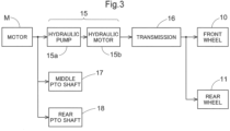
- the tractor includes an inverter 14 and an electric motor M.
- the battery 4 for traveling supplies electric power to the inverter 14.
- the inverter 14 converts DC power supplied from the battery 4 for traveling to AC power, and supplies the AC power to the electric motor M.
- the electric motor M is driven by the AC power supplied from the inverter 14.
- the tractor includes a hydraulic continuously variable transmission 15 and a transmission 16.
- the hydraulic continuously variable transmission 15 includes a hydraulic pump 15a and a hydraulic motor 15b.
- the hydraulic pump 15a is driven by rotational motive power transmitted from the electric motor M. As a result of the hydraulic pump 15a being driven, rotational motive power is output from the hydraulic motor 15b.
- the hydraulic continuously variable transmission 15 is configured to change the speed of rotational motive power between the hydraulic pump 15a and the hydraulic motor 15b. Also, the hydraulic continuously variable transmission 15 is configured to be capable of changing the transmission ratio in a stepless manner.
- the rotational motive power output from the hydraulic motor 15b is transmitted to the transmission 16.
- the speed of the rotational motive power transmitted to the transmission 16 is changed by a gear transmission mechanism included in the transmission 16, and the rotational motive power is distributed to the left and right front wheels 10 and the left and right rear wheels 11.
- the left and right front wheels 10 and the left and right rear wheels 11 are driven.
- the tractor also includes a middle PTO shaft 17 and a rear PTO shaft 18.
- Rotational motive power output from the electric motor M is distributed to the hydraulic pump 15a, the middle PTO shaft 17, and the rear PTO shaft 18.
- the middle PTO shaft 17 and the rear PTO shaft 18 are rotated by the distributed rotational motive power.
- a work device is connected to the middle PTO shaft 17 or the rear PTO shaft 18, the work device is driven by rotational motive power transmitted by the middle PTO shaft 17 or the rear PTO shaft 18.
- a grass cutting device 19 is connected to the middle PTO shaft 17 as shown in FIG. 2 .
- the grass cutting device 19 is driven by rotational motive power transmitted by the middle PTO shaft 17.
- a configuration related to the control of the electric motor M includes an accelerator 33, a control device 34 configured to control the operation of the electric motor M, and the inverter 14.
- the accelerator 33 is in the vicinity of the steering wheel 32.
- the accelerator 33 includes a pivotable lever and a potentiometer configured to be operated by pivoting the lever.
- the accelerator 33 is connected to the control device 34.
- the control device 34 is connected to the inverter 14 via a signal harness 35.
- the control device 34 is configured to issue a command to the inverter 14 in response to a command from the accelerator 33.
- the inverter 14 is configured to control the output of the electric motor M by adjusting electric power supplied to the electric motor M from the battery 4 for traveling, according to the command from the control device 34.
- the battery 4 for traveling is chargeable by an external power supply device KD.
- the tractor includes a charging connection section 37 to which a power supply connector 36 of the power supply device KD is connectable.
- the charging connection section 37 is inside the cover member 12 and is configured to be exposed to the outside when the cover member 12 is pivoted open.
- the control device 34 is configured to control the operation of the electric motor M and to control the charge state during charging by the power supply device KD.
- the power supply connector 36 of the power supply device KD is connectable to the charging connection section 37.
- the charging connection section 37 is in conformity with commonly used standard specifications.
- the battery 4 for traveling is charged via an electric power supply line 39 while the power supply connector 36 is connected to the charging connection section 37.
- the battery 4 for traveling supplies high-voltage (e.g., several tens to several hundreds of volts) electric power to the inverter 14 and the electric motor M for traveling via the electric power supply line 39.
- the battery 4 for traveling uses, for example, a lithium ion battery and has a configuration in which a large number of small-sized low-voltage unit cells, which are not shown, are stacked, and the exterior of the stack is enclosed in a housing in a sealed state. Therefore, heat is likely to be trapped in the battery, and once the internal temperature of the battery increases, the temperature is unlikely to decrease.
- the battery for traveling includes a temperature sensor 40 (40a) configured to detect the internal temperature of this battery. Information detected by the temperature sensor 40 (40a) is input to the control device 34.
- the tractor includes a battery 41 for electric components for supplying electric power to the control device 34 and other electric components.
- the battery 41 for electric components supplies low-voltage (12 V) electric power in order to drive the electric components.
- the battery 41 for electric components is charged using electric power supplied from the battery 4 for traveling via a DC/DC converter 42.
- the electric motor M, the inverter 14, and the DC/DC converter 42 may also be provided with temperature sensors 40 (40b, 40c, and 40d).
- An operation panel 43 in the driving section 3 includes a switching operation unit 44 serving as a start command means capable of switching the control device 34 between an operable state and an inactive state.
- the switching operation unit 44 is provided below the steering wheel 32 on the operation panel 43.
- the switching operation unit 44 includes an insertion slot 46 as a securing portion where a portable operation key 45 can be inserted and secured, and a manually-pressable push-button switch 47.
- the control device 34 can be switched from the inactive state to the operable state by the switch 47 being pressed while the operation key 45 is inserted and secured in the insertion slot 46.
- the operation panel 43 includes a meter panel 48 configured to display, for example, traveling conditions of the vehicle body, working conditions, battery information (amount of charge and temperature), and the like.
- the meter panel 48 is connected the control device 34, and the control device 34 controls the operation of the meter panel 48.
- the control device 34, the inverter 14, the battery 4 for traveling (including the temperature sensor 40a), the DC/DC converter 42, the meter panel 48, the charging connection section 37, and the like are connected via the CAN (Controller Area Network) type signal harness 35 so as to communicate data.
- the control device 34 communicates with the charging connection section 37 via a charging communication harness 49, and information on whether or not the power supply connector 36 is connected to the charging connection section 37, information on a charging current required by the work vehicle, and the like are transmitted therebetween.
- the charging connection section 37 and the power supply device KD are also configured such that signals can be communicated therebetween. Furthermore, information on the operation performed on the switching operation unit 44 is input to the control device 34.
- the control device 34 is ready to charge the battery 4 for traveling using the power supply device KD.
- the control device 34 is configured to adjust the charging current based on the detection results of the temperature sensor 40. More specifically, in the battery 4 for traveling, the relationship between the state of charge (SOC) of the battery 4 for traveling and the maximum allowable value of the charging current depends on the temperature of the battery 4 for traveling. Therefore, during charging, the current value needs to be changed and adjusted based on changes in the internal temperature and the state of charge so as not to exceed the aforementioned maximum allowable current value.
- SOC state of charge
- the control device 34 is configured such that, when the control device 34 is commanded to perform scheduled charging while it is ready to charge the battery 4 for traveling using the power supply device KD, the control device 34 executes scheduled charging control to charge the battery 4 for traveling based on the detection results of the temperature sensor 40 in such a manner that the lower the detected ambient temperature, the closer the time at which charging is completed is to a planned work start time. That is to say, in this embodiment, the temperature sensor 40 functions as an ambient temperature detecting means G.
- step #01 When charging is ready, with the power supply connector 36 connected to the charging connection section 37 while the control device 34 is in the operable state, if scheduled charging is commanded by operating the scheduled charging switch 50 (step #01), the ambient temperature at that time is measured based on the detection results of the temperature sensor 40 (step #02).
- the internal temperature of the battery 4 for traveling does not correspond to the ambient temperature because the internal temperature has increased due to heat generated by current applied to the battery 4 for traveling, but then, after some time has elapsed and the increased internal temperature due to the current applied to the battery 4 for traveling has decreased, the internal temperature corresponds to the ambient temperature. Therefore, the ambient temperature can be estimated based on the detection results of the temperature sensor 40.
- step #03 the time required to complete charging is predicted based on the ambient temperature and the charging characteristics of the battery 4 for traveling.
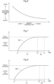
- the correlation between the ambient temperature and the time required to charge the battery to a fully charged state can be obtained and stored as map data in advance as shown in FIG. 6 , for example, or can be obtained using an arithmetic formula or the like. Accordingly, a required time T1 (see FIGS. 7 and 8 ) until a planned charge completion time tk at which charging will be completed can be predicted based on the ambient temperature.
- a standby time T2 (see FIGS 7 and 8 ) between the planned charge completion time tk and a planned work start time te is set such that the lower the ambient temperature, the shorter the standby time T2 (step #04).
- the ambient temperature is low, such as in winter, the temperature of the battery 4 for traveling does not increase to a very high temperature even if the battery is charged to a fully charged state, and therefore, there is no risk of the temperature reaching the allowable upper limit temperature even if the tractor performs work while traveling immediately thereafter.
- the standby time T2 between the completion of charging and the start of work is set to be long as indicated by the line W1 in FIG. 7
- the standby time T2 is set to be short as indicated by the line W2 in FIG. 8 .
- the time that is earlier than the planned work start time te by a total of the required time T 1 and the standby time T2 is set as a planned charge start time ts (step #05).
- the planned work start time te is preset by the operator.
- steps #06 and #07 a charging operation for charging the battery 4 for traveling using the power supply device KD is performed.
- charging is stopped (steps #08 and #09).
- the meter panel may display a notification to the effect that there is a risk of an increase in temperature of the battery 4 for traveling.
- the temperature sensor 40a of the battery 4 for traveling is used as an example here, the temperature sensor 40b of the electric motor M, the temperature sensor 40c of the inverter 14, or the temperature sensor 40d of the DC/DC converter 42 may also be used as the temperature sensor 40 serving as the ambient temperature detecting means G.
- accuracy is slightly lower than when the temperature sensor 40a of the battery 4 for traveling is used for measurement, but there are often no problems in practical use, and thus, these temperature sensors may be used.
- the present invention is applicable to electric work vehicles for performing various types of work such as agricultural work.
Landscapes
- Engineering & Computer Science (AREA)
- Power Engineering (AREA)
- Transportation (AREA)
- Mechanical Engineering (AREA)
- Sustainable Development (AREA)
- Sustainable Energy (AREA)
- Life Sciences & Earth Sciences (AREA)
- Manufacturing & Machinery (AREA)
- Chemical & Material Sciences (AREA)
- Chemical Kinetics & Catalysis (AREA)
- Electrochemistry (AREA)
- General Chemical & Material Sciences (AREA)
- Electric Propulsion And Braking For Vehicles (AREA)
- Charge And Discharge Circuits For Batteries Or The Like (AREA)
- Secondary Cells (AREA)
Applications Claiming Priority (2)
| Application Number | Priority Date | Filing Date | Title |
|---|---|---|---|
| JP2022015810A JP7734602B2 (ja) | 2022-02-03 | 2022-02-03 | 電動作業車 |
| PCT/JP2022/039217 WO2023149026A1 (ja) | 2022-02-03 | 2022-10-21 | 電動作業車 |
Publications (2)
| Publication Number | Publication Date |
|---|---|
| EP4475384A1 true EP4475384A1 (de) | 2024-12-11 |
| EP4475384A4 EP4475384A4 (de) | 2026-01-21 |
Family
ID=87552104
Family Applications (1)
| Application Number | Title | Priority Date | Filing Date |
|---|---|---|---|
| EP22924931.3A Pending EP4475384A4 (de) | 2022-02-03 | 2022-10-21 | Elektrisches arbeitsfahrzeug |
Country Status (4)
| Country | Link |
|---|---|
| US (1) | US20240383362A1 (de) |
| EP (1) | EP4475384A4 (de) |
| JP (1) | JP7734602B2 (de) |
| WO (1) | WO2023149026A1 (de) |
Cited By (1)
| Publication number | Priority date | Publication date | Assignee | Title |
|---|---|---|---|---|
| US20230249584A1 (en) * | 2022-02-04 | 2023-08-10 | Honda Motor Co., Ltd. | Charging control system |
Family Cites Families (4)
| Publication number | Priority date | Publication date | Assignee | Title |
|---|---|---|---|---|
| JP5696377B2 (ja) * | 2010-06-11 | 2015-04-08 | トヨタ自動車株式会社 | 車両用制御装置および車両用制御方法 |
| JP6493148B2 (ja) * | 2015-10-20 | 2019-04-03 | トヨタ自動車株式会社 | 充電装置 |
| JP7068959B2 (ja) | 2018-08-02 | 2022-05-17 | 株式会社クボタ | バッテリ用コネクタアセンブリ及びバッテリ装置 |
| US12081062B2 (en) * | 2019-11-08 | 2024-09-03 | Oshkosh Corporation | Power system for a vehicle |
-
2022
- 2022-02-03 JP JP2022015810A patent/JP7734602B2/ja active Active
- 2022-10-21 EP EP22924931.3A patent/EP4475384A4/de active Pending
- 2022-10-21 WO PCT/JP2022/039217 patent/WO2023149026A1/ja not_active Ceased
-
2024
- 2024-07-19 US US18/777,647 patent/US20240383362A1/en active Pending
Cited By (1)
| Publication number | Priority date | Publication date | Assignee | Title |
|---|---|---|---|---|
| US20230249584A1 (en) * | 2022-02-04 | 2023-08-10 | Honda Motor Co., Ltd. | Charging control system |
Also Published As
| Publication number | Publication date |
|---|---|
| JP2023113436A (ja) | 2023-08-16 |
| EP4475384A4 (de) | 2026-01-21 |
| WO2023149026A1 (ja) | 2023-08-10 |
| JP7734602B2 (ja) | 2025-09-05 |
| US20240383362A1 (en) | 2024-11-21 |
Similar Documents
| Publication | Publication Date | Title |
|---|---|---|
| US6483272B1 (en) | Power system for electric vehicle | |
| EP1020319B1 (de) | Hilfsvorrichtung zur Benützung in einem Elektrofahrzeug | |
| US5578915A (en) | Dynamic battery state-of-charge and capacity determination | |
| US5623194A (en) | Apparatus for monitoring and controlling charging of a battery for a hybrid or electric vehicle | |
| EP4475385A1 (de) | Elektrisches arbeitsfahrzeug | |
| US20240383362A1 (en) | Electric work vehicle | |
| US11872903B2 (en) | System and method for recalibrating a traction battery through bi-directional power transfer | |
| EP1220350B1 (de) | Elektrische vorrichtung mit zeitgeber | |
| JP2024120921A5 (de) | ||
| US20240399927A1 (en) | Electric work vehicle | |
| CN117681731A (zh) | 一种路程计算动力电池加热远程控制系统、方法及车辆 | |
| JP2023097970A (ja) | 電動作業車 | |
| JPH1016868A (ja) | 電気自転車 | |
| EP4582291A1 (de) | Elektrisches arbeitsfahrzeug | |
| JP3178139B2 (ja) | 電気自動車用制御装置 | |
| JP7507742B2 (ja) | 電動作業車 | |
| JP2024025397A (ja) | 充電システム及び充電方法 | |
| EP4566863A1 (de) | Elektrisches arbeitsfahrzeug | |
| JP4158887B2 (ja) | 電気車の電力供給装置 | |
| JP2000195559A (ja) | 電池パック | |
| JP2008089519A (ja) | 充電状態検出装置及び検出方法 | |
| JP7632063B2 (ja) | 充電制御装置 | |
| US20240059178A1 (en) | Electric work vehicle | |
| JP7631260B2 (ja) | 作業車両 | |
| JP7519984B2 (ja) | 電動作業車 |
Legal Events
| Date | Code | Title | Description |
|---|---|---|---|
| STAA | Information on the status of an ep patent application or granted ep patent |
Free format text: STATUS: THE INTERNATIONAL PUBLICATION HAS BEEN MADE |
|
| PUAI | Public reference made under article 153(3) epc to a published international application that has entered the european phase |
Free format text: ORIGINAL CODE: 0009012 |
|
| STAA | Information on the status of an ep patent application or granted ep patent |
Free format text: STATUS: REQUEST FOR EXAMINATION WAS MADE |
|
| 17P | Request for examination filed |
Effective date: 20240902 |
|
| AK | Designated contracting states |
Kind code of ref document: A1 Designated state(s): AL AT BE BG CH CY CZ DE DK EE ES FI FR GB GR HR HU IE IS IT LI LT LU LV MC ME MK MT NL NO PL PT RO RS SE SI SK SM TR |
|
| DAV | Request for validation of the european patent (deleted) | ||
| DAX | Request for extension of the european patent (deleted) | ||
| A4 | Supplementary search report drawn up and despatched |
Effective date: 20251219 |
|
| RIC1 | Information provided on ipc code assigned before grant |
Ipc: H02J 7/04 20060101AFI20251215BHEP Ipc: B60L 50/60 20190101ALI20251215BHEP Ipc: B60L 53/14 20190101ALI20251215BHEP Ipc: B60L 58/10 20190101ALI20251215BHEP Ipc: H01M 10/44 20060101ALI20251215BHEP Ipc: H01M 10/48 20060101ALI20251215BHEP Ipc: H02J 7/00 20060101ALI20251215BHEP Ipc: H02J 7/10 20060101ALI20251215BHEP Ipc: B60L 58/12 20190101ALI20251215BHEP |