EP4475405A1 - Structure de support utilisée pendant le transport d'une machine électrique tournante sans arbre - Google Patents
Structure de support utilisée pendant le transport d'une machine électrique tournante sans arbre Download PDFInfo
- Publication number
- EP4475405A1 EP4475405A1 EP23178326.7A EP23178326A EP4475405A1 EP 4475405 A1 EP4475405 A1 EP 4475405A1 EP 23178326 A EP23178326 A EP 23178326A EP 4475405 A1 EP4475405 A1 EP 4475405A1
- Authority
- EP
- European Patent Office
- Prior art keywords
- rotor
- stator
- support structure
- electrical machine
- stator frame
- Prior art date
- Legal status (The legal status is an assumption and is not a legal conclusion. Google has not performed a legal analysis and makes no representation as to the accuracy of the status listed.)
- Pending
Links
Images





Classifications
-
- H—ELECTRICITY
- H02—GENERATION; CONVERSION OR DISTRIBUTION OF ELECTRIC POWER
- H02K—DYNAMO-ELECTRIC MACHINES
- H02K1/00—Details of the magnetic circuit
- H02K1/06—Details of the magnetic circuit characterised by the shape, form or construction
- H02K1/22—Rotating parts of the magnetic circuit
- H02K1/28—Means for mounting or fastening rotating magnetic parts on to, or to, the rotor structures
- H02K1/30—Means for mounting or fastening rotating magnetic parts on to, or to, the rotor structures using intermediate parts, e.g. spiders
-
- H—ELECTRICITY
- H02—GENERATION; CONVERSION OR DISTRIBUTION OF ELECTRIC POWER
- H02K—DYNAMO-ELECTRIC MACHINES
- H02K15/00—Processes or apparatus specially adapted for manufacturing, assembling, maintaining or repairing of dynamo-electric machines
- H02K15/16—Centring rotors within the stators
-
- B—PERFORMING OPERATIONS; TRANSPORTING
- B65—CONVEYING; PACKING; STORING; HANDLING THIN OR FILAMENTARY MATERIAL
- B65D—CONTAINERS FOR STORAGE OR TRANSPORT OF ARTICLES OR MATERIALS, e.g. BAGS, BARRELS, BOTTLES, BOXES, CANS, CARTONS, CRATES, DRUMS, JARS, TANKS, HOPPERS, FORWARDING CONTAINERS; ACCESSORIES, CLOSURES, OR FITTINGS THEREFOR; PACKAGING ELEMENTS; PACKAGES
- B65D25/00—Details of other kinds or types of rigid or semi-rigid containers
- B65D25/02—Internal fittings
- B65D25/10—Devices to locate articles in containers
-
- B—PERFORMING OPERATIONS; TRANSPORTING
- B65—CONVEYING; PACKING; STORING; HANDLING THIN OR FILAMENTARY MATERIAL
- B65D—CONTAINERS FOR STORAGE OR TRANSPORT OF ARTICLES OR MATERIALS, e.g. BAGS, BARRELS, BOTTLES, BOXES, CANS, CARTONS, CRATES, DRUMS, JARS, TANKS, HOPPERS, FORWARDING CONTAINERS; ACCESSORIES, CLOSURES, OR FITTINGS THEREFOR; PACKAGING ELEMENTS; PACKAGES
- B65D25/00—Details of other kinds or types of rigid or semi-rigid containers
- B65D25/20—External fittings
- B65D25/24—External fittings for spacing bases of containers from supporting surfaces, e.g. legs
-
- B—PERFORMING OPERATIONS; TRANSPORTING
- B65—CONVEYING; PACKING; STORING; HANDLING THIN OR FILAMENTARY MATERIAL
- B65D—CONTAINERS FOR STORAGE OR TRANSPORT OF ARTICLES OR MATERIALS, e.g. BAGS, BARRELS, BOTTLES, BOXES, CANS, CARTONS, CRATES, DRUMS, JARS, TANKS, HOPPERS, FORWARDING CONTAINERS; ACCESSORIES, CLOSURES, OR FITTINGS THEREFOR; PACKAGING ELEMENTS; PACKAGES
- B65D81/00—Containers, packaging elements, or packages, for contents presenting particular transport or storage problems, or adapted to be used for non-packaging purposes after removal of contents
- B65D81/02—Containers, packaging elements, or packages, for contents presenting particular transport or storage problems, or adapted to be used for non-packaging purposes after removal of contents specially adapted to protect contents from mechanical damage
- B65D81/05—Containers, packaging elements, or packages, for contents presenting particular transport or storage problems, or adapted to be used for non-packaging purposes after removal of contents specially adapted to protect contents from mechanical damage maintaining contents at spaced relation from package walls, or from other contents
-
- B—PERFORMING OPERATIONS; TRANSPORTING
- B65—CONVEYING; PACKING; STORING; HANDLING THIN OR FILAMENTARY MATERIAL
- B65D—CONTAINERS FOR STORAGE OR TRANSPORT OF ARTICLES OR MATERIALS, e.g. BAGS, BARRELS, BOTTLES, BOXES, CANS, CARTONS, CRATES, DRUMS, JARS, TANKS, HOPPERS, FORWARDING CONTAINERS; ACCESSORIES, CLOSURES, OR FITTINGS THEREFOR; PACKAGING ELEMENTS; PACKAGES
- B65D85/00—Containers, packaging elements or packages, specially adapted for particular articles or materials
- B65D85/30—Containers, packaging elements or packages, specially adapted for particular articles or materials for articles particularly sensitive to damage by shock or pressure
-
- B—PERFORMING OPERATIONS; TRANSPORTING
- B65—CONVEYING; PACKING; STORING; HANDLING THIN OR FILAMENTARY MATERIAL
- B65D—CONTAINERS FOR STORAGE OR TRANSPORT OF ARTICLES OR MATERIALS, e.g. BAGS, BARRELS, BOTTLES, BOXES, CANS, CARTONS, CRATES, DRUMS, JARS, TANKS, HOPPERS, FORWARDING CONTAINERS; ACCESSORIES, CLOSURES, OR FITTINGS THEREFOR; PACKAGING ELEMENTS; PACKAGES
- B65D85/00—Containers, packaging elements or packages, specially adapted for particular articles or materials
- B65D85/68—Containers, packaging elements or packages, specially adapted for particular articles or materials for machines, engines or vehicles in assembled or dismantled form
-
- H—ELECTRICITY
- H02—GENERATION; CONVERSION OR DISTRIBUTION OF ELECTRIC POWER
- H02K—DYNAMO-ELECTRIC MACHINES
- H02K1/00—Details of the magnetic circuit
- H02K1/06—Details of the magnetic circuit characterised by the shape, form or construction
- H02K1/12—Stationary parts of the magnetic circuit
- H02K1/18—Means for mounting or fastening magnetic stationary parts on to, or to, the stator structures
-
- H—ELECTRICITY
- H02—GENERATION; CONVERSION OR DISTRIBUTION OF ELECTRIC POWER
- H02K—DYNAMO-ELECTRIC MACHINES
- H02K1/00—Details of the magnetic circuit
- H02K1/06—Details of the magnetic circuit characterised by the shape, form or construction
- H02K1/22—Rotating parts of the magnetic circuit
- H02K1/27—Rotor cores with permanent magnets
- H02K1/2706—Inner rotors
- H02K1/272—Inner rotors the magnetisation axis of the magnets being perpendicular to the rotor axis
- H02K1/274—Inner rotors the magnetisation axis of the magnets being perpendicular to the rotor axis the rotor consisting of two or more circumferentially positioned magnets
- H02K1/2753—Inner rotors the magnetisation axis of the magnets being perpendicular to the rotor axis the rotor consisting of two or more circumferentially positioned magnets the rotor consisting of magnets or groups of magnets arranged with alternating polarity
- H02K1/278—Surface mounted magnets; Inset magnets
-
- H—ELECTRICITY
- H02—GENERATION; CONVERSION OR DISTRIBUTION OF ELECTRIC POWER
- H02K—DYNAMO-ELECTRIC MACHINES
- H02K1/00—Details of the magnetic circuit
- H02K1/06—Details of the magnetic circuit characterised by the shape, form or construction
- H02K1/22—Rotating parts of the magnetic circuit
- H02K1/28—Means for mounting or fastening rotating magnetic parts on to, or to, the rotor structures
-
- H—ELECTRICITY
- H02—GENERATION; CONVERSION OR DISTRIBUTION OF ELECTRIC POWER
- H02K—DYNAMO-ELECTRIC MACHINES
- H02K15/00—Processes or apparatus specially adapted for manufacturing, assembling, maintaining or repairing of dynamo-electric machines
-
- H—ELECTRICITY
- H02—GENERATION; CONVERSION OR DISTRIBUTION OF ELECTRIC POWER
- H02K—DYNAMO-ELECTRIC MACHINES
- H02K15/00—Processes or apparatus specially adapted for manufacturing, assembling, maintaining or repairing of dynamo-electric machines
- H02K15/02—Processes or apparatus specially adapted for manufacturing, assembling, maintaining or repairing of dynamo-electric machines of stator or rotor bodies
- H02K15/03—Processes or apparatus specially adapted for manufacturing, assembling, maintaining or repairing of dynamo-electric machines of stator or rotor bodies having permanent magnets
-
- H—ELECTRICITY
- H02—GENERATION; CONVERSION OR DISTRIBUTION OF ELECTRIC POWER
- H02K—DYNAMO-ELECTRIC MACHINES
- H02K21/00—Synchronous motors having permanent magnets; Synchronous generators having permanent magnets
- H02K21/12—Synchronous motors having permanent magnets; Synchronous generators having permanent magnets with stationary armatures and rotating magnets
- H02K21/14—Synchronous motors having permanent magnets; Synchronous generators having permanent magnets with stationary armatures and rotating magnets with magnets rotating within the armatures
-
- H—ELECTRICITY
- H02—GENERATION; CONVERSION OR DISTRIBUTION OF ELECTRIC POWER
- H02K—DYNAMO-ELECTRIC MACHINES
- H02K2213/00—Specific aspects, not otherwise provided for and not covered by codes H02K2201/00 - H02K2211/00
- H02K2213/09—Machines characterised by the presence of elements which are subject to variation, e.g. adjustable bearings, reconfigurable windings, variable pitch ventilators
-
- H—ELECTRICITY
- H02—GENERATION; CONVERSION OR DISTRIBUTION OF ELECTRIC POWER
- H02K—DYNAMO-ELECTRIC MACHINES
- H02K7/00—Arrangements for handling mechanical energy structurally associated with dynamo-electric machines, e.g. structural association with mechanical driving motors or auxiliary dynamo-electric machines
- H02K7/18—Structural association of electric generators with mechanical driving motors, e.g. with turbines
- H02K7/1807—Rotary generators
- H02K7/1823—Rotary generators structurally associated with turbines or similar engines
Definitions
- the present invention relates to support structures used during transportation of a rotating electrical machine, and in particular when transporting a shaft-less rotating electrical machine.
- the present invention also relates to a shaft-less rotating electrical machine comprising the support structure.
- Rotating electrical machines are typically supplied to customers with a rotor shaft.
- the assembled electrical motor has a stator that is supported by a stator frame and a rotor that is mechanically fixed to the rotor shaft.
- the electrical machine may be transported to the customer in a suitable package (e.g., a container or crate) with the rotor shaft locked in position so that the rotor is secured inside the surrounding stator.
- the rotor shaft may be secured to the stator frame by a rigid beam or bracket. Locking or securing the rotor shaft to the stator frame prevents any radial or axial movement of the rotor relative to the stator during transportation of the electrical machine.
- Rotating electrical machines for power take-off/power take-in (PTO/PTI) applications are normally supplied to the customer without a rotor shaft.
- Such shaft-less rotating electrical machines are designed to be inserted into an existing shaftline, e.g., the propulsion shaft of a marine vessel.
- the propulsion shaft may be driven by a main engine of the marine vessel.
- the conventional generator sets of the marine vessel may be stopped and electrical power is supplied by the electrical machine operating as a generator.
- the rotor of the electrical machine is driven by the propulsion shaft.
- the conventional generator sets are operated if required and additional mechanical propulsion power is supplied to the propulsion shaft by the electrical machine operating as a motor.
- the rotor of the electrical machine and the main engine drive the propulsion shaft.
- a shaft-less rotating electrical machine cannot be transported in its assembled condition - i.e., with its rotor positioned inside the stator - because there is no rotor shaft that can be locked or secured to the stator frame.
- the rotor and the stator frame are therefore transported separately - i.e., in separate packages. If the rotor is a permanent magnet rotor, its package will normally be a steel crate for example because of the presence of strong magnetic fields.
- the shaft-less rotating electrical machine After delivery to the customer, the shaft-less rotating electrical machine must first be assembled by inserting the rotor into the stator (which is a very delicate and time-consuming process when dealing with permanent magnet machines) before the rotor is mechanically connected to the shaftline, e.g., using one or more mechanical fixings such as bolts or screws.
- the present invention allows a shaft-less rotating electrical machine to be transported in its assembled condition - i.e., with the rotor stably supported inside the stator - and ready for installation to an existing shaftline.
- the present invention provides a support structure used for transportation of a shaft-less rotating electrical machine (e.g., a motor or generator) comprising a stator supported by a stator frame, and a rotor that is mechanically connectable to a shaftline (e.g., using one or more mechanical fixings such as screws or bolts) and is positioned radially inside the stator, the support structure comprising:
- the present invention further provides a shaft-less rotating electrical machine comprising the support structure described above, where the one or more supports are positioned in the air gap and the one or more transport brackets are fixedly connected between the stator frame and the rotor.
- fixedly connectable and “fixedly connected” means that the components are firmly or securely connectable or connected (or attachable or attached) to each other in use, e.g., to prevent relative movement between the rotor and the stator in the case of the one or more transport brackets, but it does not necessarily mean that the components are permanently connected or attached.
- the components may be removably or releasably connectable or connected (or attached) and still be fixedly connected.
- the electrical machine may have any suitable construction.
- the rotor may be a permanent magnet rotor and include a plurality of permanent magnets circumferentially spaced around the rotor.
- the permanent magnets may be positioned on the surface of the rotor, e.g., using magnet carrier assemblies that are fixed to the rotor surface, or held in position using a sleeve or band.
- the permanent magnets may be embedded within the rotor.
- a plurality of individual supports may be positionable or positioned in the air gap between the rotor and the stator.
- the supports are normally circumferentially spaced around the air gap.
- Each support may extend along substantially the whole axial length of the rotor and may be inserted into the air gap from one axial end of the electrical machine, or each support may extend only partly along the axial length of the rotor. In the latter case, a first plurality of supports may be inserted into the air gap from one axial end of the electrical machine and a second plurality of supports may be inserted into the air gap from the other axial end of the electrical machine, so that the rotor is supported at both axial ends.
- Each support may be made of any suitable non-magnetic material (e.g., a synthetic polymer material) and have any suitable construction. Any suitable number of supports may be used. If each support extends along substantially the whole axial length of the rotor, so that both axial ends of the rotor are supported by each support, it may be that a minimum number of supports is three. In one arrangement, four to seven supports may be used. In one arrangement, eight or more supports may be used.
- the one or more supports provide radial support for the rotor and maintain the radial air gap - i.e., they are designed to prevent the radially outer surface of the rotor from contacting the radially inner surface of the stator during transportation and installation to the existing shaftline.
- the one or more supports are removed from the air gap when they are no longer required. This is normally after the rotor of the electrical machine has been mechanically connected to the shaftline.
- the one or more transport brackets provide axial support for the rotor - i.e., they are designed to prevent the rotor from moving relative to the stator and the stator frame in the axial direction.
- the one or more transport brackets may also prevent the rotor from rotating within the stator.
- the support structure may support the rotor inside the stator when the axis of the electrical machine is substantially horizontal - which may be how it is typically transported and orientated for installation - and when the axis is substantially vertical - which is how the electrical machine may be orientated during manufacture or assembly, for example.
- the support structure may support the rotor during lifting and turning of the electrical machine.
- the support structure is primarily designed to support the rotor during transportation of the electrical machine, it may also provide support in other circumstances, e.g., during manufacture or assembly, or after the electrical machine has been delivered and installed.
- One or more transport brackets may be provided at one or both axial ends of the rotor.
- One or more transport brackets may be fixedly connectable between the stator frame and a first axial end of the rotor and one or more transport brackets may be fixedly connectable between the stator frame and a second axial end of the rotor.
- Each transport bracket may have any suitable rigid construction and is adapted to prevent at least axial movement between the rotor and the stator frame.
- Each transport bracket will typically be constructed to withstand any loads such as acceleration and shock loads that might be expected during transportation so that the rotor remains properly supported at all times.
- the one or more transport brackets may be removed from the electrical machine after transportation when they are no longer required to support the rotor. However, one or more parts of each transport bracket may remain in place in the electrical machine and may be used subsequently to fix the rotor relative to the stator frame.
- the one or more parts that are designed to remain in place may be integrally formed as part of the stator frame or rotor, or may be permanently fixed to the stator frame or rotor.
- the one or more parts that are designed to remain in place may also be removably connectable or connected to the stator frame or rotor, but simply not removed or released after the installation process has been completed.
- the one or more parts of each transport bracket that are designed to be removed may be removably connectable or connected to the stator frame or rotor, and/or to any other part of each transport bracket such as a fixed part, using one or more mechanical fixings such as bolts, studs or screws, for example.
- Such parts may be fixedly connectable or connected to the stator frame or rotor, and/or another part of the transport bracket, by inserting and tightening the one or more mechanical fixings and then released or removed by untightening and removing them.
- Such parts may also be designed to be removably connectable or connected without the need for one or more mechanical fixings - e.g., the parts may be shaped to receive or engage with the stator frame or rotor.
- the one or more parts of each transport bracket typically define a rigid support component that extends between the rotor and the stator frame to prevent relative movement in the axial direction.
- the or each transport bracket may include at least one first part that is fixedly connectable or connected to the stator frame and at least one second part that is fixedly connectable or connected to the rotor.
- the at least one first part may be fixedly connectable or connected to the at least one second part, or the or each transport bracket may include at least one third part that is fixedly connectable or connected between the at least one first part and the at least one second part.
- the or each third part may be removably connectable or connected to the first and/or second parts. For example, this allows one or both of the first and second parts to be permanently fixed to the stator frame and the rotor.
- each third part may extend substantially axially.
- the or each third part may be formed as a tie rod, where optionally at least the ends of the tie rod have an external screw-thread.
- the external screw-thread may extend along substantially the whole length of the tie rod.
- each tie rod may be screwed into an internally screw-threaded opening provided in one of a first part and a second part of each transport bracket and be received through an opening in the other one of the first part and the second part and fixedly connected thereto using one or more mechanical fixings, e.g., nuts.
- the at least one first part may be permanently connectable or connected to the stator frame - i.e., it may be designed not to be removed.
- the at least one first part may extend substantially radially.
- the at least one second part may be designed to be removably connectable or connected to the rotor.
- Each second part may be substantially U-shaped and include a channel that is designed to receive or engage with part of the rotor so that it is removably connectable or connected to the rotor without the need for one or more mechanical fixings. This may make it easier to fit the second part(s) of each transport bracket.
- first part that is fixedly connectable or connected to the stator frame - e.g., an annular first part that extends around the circumference of the stator frame, or a linear first part that extends diametrically across the axial end of the stator frame - and a plurality of second parts that are fixedly connectable or connected to the rotor.
- the plurality of second parts may be circumferentially spaced around the rotor.
- Each second part may be fixedly connectable or connected to the first part by a respective third part - i.e., so that there is a plurality of third parts and where each second part is connected to the same first part.
- first parts that are fixedly connectable or connected to the stator frame and a plurality of second parts that are fixedly connectable or connected to the rotor.
- the plurality of first parts may be circumferentially spaced around the stator frame and the plurality of second parts may be circumferentially spaced around the rotor.
- Each second part may be fixedly connectable or connected to a respective first part by a respective third part - i.e., so that there is a plurality of third parts and where each second part is connected to a separate first part.
- transport brackets circumferentially spaced apart around the stator frame where each transport bracket includes a first part, a second part and a third part.
- the one or more transport brackets are constructed may depend on how the rotor is received in the stator during manufacture. For example, if the rotor is inserted radially into the stator frame, e.g., from above, the one or more transport bracket may extend into or across the axial end of the stator frame. But if the rotor is inserted axially into the stator, the one or more transport brackets may have to be designed to allow such axial insertion of the rotor, or to be fixedly connectable or connected to the stator frame after the rotor has been inserted.
- the one or more transport brackets may be fixedly connectable or connected to any suitable part of the stator frame - e.g., to its inner cylindrical surface or drum, or to an axial end surface.
- the stator frame may include one or more mountings for each transport bracket.
- Each mounting may include one or more internally screw-threaded openings for receiving one or more externally screw-threaded mechanical fixings, e.g., bolts, studs or screws, for fixedly connecting the transport bracket(s) to the stator frame.
- the one or more transport brackets may be fixedly connectable or connected to any suitable part of the rotor.
- the present invention further provides a method of preparing a shaft-less rotating electrical machine for transport, the shaft-less rotating electrical machine comprising a stator supported by a stator frame, and a rotor that is mechanically connectable to a shaftline and is positioned radially inside the stator, the method comprising:
- the one or more supports and the one or more transport brackets that provide a support structure for the shaft-less rotating electrical machine during transport may be as described above.
- a shaft-less rotating electrical machine e.g., a permanent magnet synchronous machine (PMSM)
- PMSM permanent magnet synchronous machine
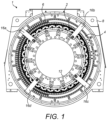
- the rotor 2 and the stator 4 are separated by an annular air gap 10.
- the rotor 2 includes a rotor flange 12 that allows the rotor to be mechanically connected to a shaftline (not shown), e.g., the propulsion shaft of a marine vessel.
- a shaftline not shown
- the electrical machine 1 is shown ready for transportation with the rotor 2 supported within the stator frame 8 by a support structure.
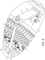
- the support structure includes a plurality of air gap packers 14 that are positioned in the air gap 10. Although Figures 3 and 6 only show a single packer 14 in detail, it will be readily appreciated that the packers are circumferentially spaced around the air gap 10. In one arrangement, eight packers 14 may be used and they are equally spaced around the rotor 2. Each packer 14 extends along substantially the whole axial length of the rotor 2 and may be inserted into the air gap 10 from one axial end of the electrical machine 1.
- Each packer 14 is typically a few millimetres thick (e.g., about 2 to 6 mm) and may be made of a suitable non-magnetic material such as a synthetic polymer like Nylatron GS, which includes the addition of molybdenum disulphide to a nylon base. Nylatron GS has excellent mechanical strength, stiffness, hardness, good sliding properties, wear resistance and machinability.
- the packers 14 provide radial support for the rotor 2 and maintain the radial air gap - i.e., they are designed to prevent the radially outer surface of the rotor 2 from contacting the radially inner surface of the stator 4 during transportation.
- a single packer 14 is shown in more detail and separately from the rest of the electrical machine in Figures 4 and 5 .
- the support structure also includes a plurality of transport brackets 16 that provide axial support for the rotor 2 - i.e., they are designed to prevent the rotor from moving relative to the stator 4 and the supporting stator frame 8 in the axial direction.
- transport brackets 16a, 16b, ..., 16d are provided at a first axial end of the stator frame 8. Another four transport brackets are similarly provided at a second axial end of the stator frame 8 and one of them can be seen in Figure 2 .
- the transport brackets 16 are circumferentially spaced around each axial end of the stator frame 8 as shown.
- each transport bracket 16 includes a first part 18 made of mild steel plate having a general L-shape with a base plate 20 and a support plate 22.
- the base plate 20 and the support plate 22 are arranged substantially perpendicular to each other.
- a triangular-shaped reinforcing rib 24 extends between the base plate 20 and the support plate 22.
- the base plate 20 includes four openings 26 for receiving externally screw-threaded bolts 29.
- the base plate 20 of each transport bracket 16 is positioned on a mounting 28 formed on the inner cylindrical surface of the stator frame 8.
- Each mounting 28 includes four internally screw-threaded openings.
- Each transport bracket 16 is therefore fixedly connected to the stator frame 8 by inserting the bolts 29 through the openings 26 in the base plate 20 and screwing them into the aligned internally screw-threaded openings in the corresponding mounting 28.
- each support plate 22 includes an opening 30.
- each transport bracket 16 extends radially inwardly when mounted to the stator frame 8 and passes over the air gap 10.
- the first part 18 of each transport bracket 16 is fixedly connected to the stator frame 8 after the rotor 2 has been inserted axially into the stator 4 during the assembly process.
- the first part 18 of each transport bracket 16 is designed to be permanently fixed to the stator frame 8.
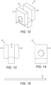
- each transport bracket 16 includes a second part 32 made of mild steel plate having a general U-shape with a pair of flanges 34, 36 that define a channel 38 therebetween.
- the flange 34 includes an internally screw-threaded opening 40.
- each transport bracket 16 includes a third part 42 (or an externally screw-threaded tie rod) made of mild steel.
- the second part 32 is fitted over part of an annular rib 44 of the rotor 2.
- the second part 32 is fitted over the annular rib 44 so that the rib is received in the channel 38 between the flanges 34, 36 and with the flange 34 facing towards the corresponding first part 18 of the transport bracket 16.
- the openings 30, 40 in the first and second parts are substantially axially aligned. From the adjacent axial end of the stator frame 8, a first end of the third part 42 is passed through the opening 30 in the first part 18 towards the second part 32.
- the first end of the third part 42 is screwed into a first nut 46 and then into the internally screw-threaded opening 40 in the flange 34 of the second part 32.
- a second nut 48 is screwed onto a second, opposite, end of the third part 42 that extends outwardly from the support plate 22 as shown most clearly in Figure 6 .
- the first and second nuts 46, 48 are tightened against the facing surfaces of the support plate 22 of the first part 18.
- the electrical machine 1 may be transported to a customer in a suitable package, e.g., a container or crate.
- the third part 42 of each transport bracket 16 may be released from the first part 18 by untightening the first and second nuts 46, 48.
- the first end of the third part 42 may be unscrewed from the second part 32 of each transport bracket 16 and the second part 32 may then be removed from the annular rib 44 of the rotor 2.
- the nut 46 is fully unscrewed from the third part 42 so that the third part may be released from the first part 18 - i.e., by removing the third part through the opening 30 in the support plate 22.
- the first part 18 of each transport bracket 16 may remain fixedly connected to the stator frame 4.
- the rotor 2 may therefore be supported or secured in the future by refitting and reconnecting the second and third parts 32, 42 of the transport brackets 16 and/or reinserting the supports 14 into the air gap 10.
- the packers 14 may be removed from the air gap 10. This is because the rotor 2 is then properly supported by the shaftline and will not move radially towards the stator 4. Any parts of the transport brackets 16 that are be designed to remain fixed to the stator frame 4 will not impede the shaftline connection.
- transport brackets 16 may optionally be provided at only one axial end of the stator frame. Any suitable number of transport brackets may be provided - with a single transport bracket at one axial end of the stator frame being an absolute minimum.
- the rotor 2 will be axially supported by one or more transport brackets at a plurality of locations around its circumference.
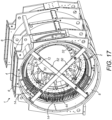
- Figures 16 to 18 show some alternative arrangements.
- Figure 16 shows an arrangement with a single linear first part 50 at one axial end of the stator frame 8.
- the first part 50 extends diametrically across the stator frame 8 and is fixedly connected to the stator frame at its ends.
- Two second parts 32 are fixedly connected to the first part 50 as described above, i.e., by a respective third part 42.
- the first part 50 includes two openings, where each opening receives an end of a respective third part 42.
- the openings in the first part 50 correspond to the openings 30 in the support plates 22 of the transport brackets 16 described above.
- the other end of each third part 42 is screwed into a respective second part 32 that is fitted on an annular rib 44 of the rotor as shown 2.
- This arrangement may be described as a single transport bracket with one first part 50 and two second and third parts 32, 42.
- Figure 17 shows an arrangement with two linear first parts 50, 52 at one axial end of the stator frame 8.
- Each first part 50, 52 extends diametrically across the stator frame 8 and is fixedly connected to the stator frame at its ends.
- the first parts 50, 52 may be fixedly connected together where they overlap or cross.
- Four second parts 32 are fixedly connected to the first parts 50, 52 as described above, i.e., by a respective third part 42.
- the first part 50 includes two openings and the second part 52 includes two openings, where each opening receives an end of a respective third part 42.
- the openings in the first and second parts 50, 52 correspond to the openings 30 in the support plates 22 of the transport brackets 16 described above.
- the other end of each third part 42 is screwed into a respective second part 32 that is fitted on an annular rib 44 of the rotor 2 as shown.
- This arrangement may be described as a single transport bracket with two first parts and four second and third parts 32, 42.
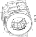
- Figure 18 shows an arrangement with a single annular first part 54 at one axial end of the stator frame 8.
- the first part 54 is fixedly connected to the stator frame 8 at a plurality of mounting locations around its circumference.
- Four second parts 32 are fixedly connected to the first part 54 as described above, i.e., by a respective third part 42.
- the first part 54 includes four openings that are circumferentially spaced around the stator frame 8, where each opening receives an end of a respective third part 42.
- the openings in the first part 54 correspond to the openings 30 in the support plates 22 of the transport brackets 16 described above.
- the other end of each third part 42 is screwed into a respective second part 32 that is fitted on an annular rib 44 of the rotor 2 as shown.
- This arrangement may be described as a single transport bracket with one first part and four second and third parts 32, 42.
Landscapes
- Engineering & Computer Science (AREA)
- Power Engineering (AREA)
- Mechanical Engineering (AREA)
- Manufacturing & Machinery (AREA)
- Manufacture Of Motors, Generators (AREA)
Priority Applications (3)
| Application Number | Priority Date | Filing Date | Title |
|---|---|---|---|
| EP23178326.7A EP4475405A1 (fr) | 2023-06-09 | 2023-06-09 | Structure de support utilisée pendant le transport d'une machine électrique tournante sans arbre |
| US18/650,943 US20240413675A1 (en) | 2023-06-09 | 2024-04-30 | Support structures used during transportation of a shaft-less rotating electrical machine |
| CN202410719326.3A CN119100003A (zh) | 2023-06-09 | 2024-06-05 | 在无轴旋转电机的运输期间使用的支承结构 |
Applications Claiming Priority (1)
| Application Number | Priority Date | Filing Date | Title |
|---|---|---|---|
| EP23178326.7A EP4475405A1 (fr) | 2023-06-09 | 2023-06-09 | Structure de support utilisée pendant le transport d'une machine électrique tournante sans arbre |
Publications (1)
| Publication Number | Publication Date |
|---|---|
| EP4475405A1 true EP4475405A1 (fr) | 2024-12-11 |
Family
ID=86760456
Family Applications (1)
| Application Number | Title | Priority Date | Filing Date |
|---|---|---|---|
| EP23178326.7A Pending EP4475405A1 (fr) | 2023-06-09 | 2023-06-09 | Structure de support utilisée pendant le transport d'une machine électrique tournante sans arbre |
Country Status (3)
| Country | Link |
|---|---|
| US (1) | US20240413675A1 (fr) |
| EP (1) | EP4475405A1 (fr) |
| CN (1) | CN119100003A (fr) |
Citations (9)
| Publication number | Priority date | Publication date | Assignee | Title |
|---|---|---|---|---|
| DE102004058349B3 (de) * | 2004-12-03 | 2006-08-17 | Zf Friedrichshafen Ag | Transportsicherung für eine elektrische Maschine sowie elektrische Maschine |
| EP1895641A2 (fr) * | 2006-08-30 | 2008-03-05 | Robert Bosch Gmbh | Entraînement direct |
| WO2009140954A2 (fr) * | 2008-05-21 | 2009-11-26 | Innovative Windpower Ag | Dispositif de fixation d'un rotor dans une machine électrique |
| EP2333325A1 (fr) * | 2009-11-26 | 2011-06-15 | Siemens Aktiengesellschaft | Système de freinage, générateur et éolienne |
| EP2232060B1 (fr) * | 2009-01-14 | 2011-08-24 | AMSC Windtec GmbH | Générateur, nacelle et procédé de montage d'une nacelle d'un convertisseur d'énergie éolienne |
| EP2437380A1 (fr) * | 2010-09-30 | 2012-04-04 | Siemens Aktiengesellschaft | Rotor, générateur et éolienne |
| EP2896824A1 (fr) * | 2014-01-20 | 2015-07-22 | Siemens Aktiengesellschaft | Système de freinage pour générateur d'éolienne |
| WO2018139936A1 (fr) * | 2017-01-26 | 2018-08-02 | Rolls-Royce Marine As | Procédé d'accès interne dans une machine électrique |
| EP4184767A1 (fr) * | 2021-11-23 | 2023-05-24 | Abb Schweiz Ag | Ensemble de machine électrique et procédé de verrouillage de rotor sur un stator |
-
2023
- 2023-06-09 EP EP23178326.7A patent/EP4475405A1/fr active Pending
-
2024
- 2024-04-30 US US18/650,943 patent/US20240413675A1/en active Pending
- 2024-06-05 CN CN202410719326.3A patent/CN119100003A/zh active Pending
Patent Citations (9)
| Publication number | Priority date | Publication date | Assignee | Title |
|---|---|---|---|---|
| DE102004058349B3 (de) * | 2004-12-03 | 2006-08-17 | Zf Friedrichshafen Ag | Transportsicherung für eine elektrische Maschine sowie elektrische Maschine |
| EP1895641A2 (fr) * | 2006-08-30 | 2008-03-05 | Robert Bosch Gmbh | Entraînement direct |
| WO2009140954A2 (fr) * | 2008-05-21 | 2009-11-26 | Innovative Windpower Ag | Dispositif de fixation d'un rotor dans une machine électrique |
| EP2232060B1 (fr) * | 2009-01-14 | 2011-08-24 | AMSC Windtec GmbH | Générateur, nacelle et procédé de montage d'une nacelle d'un convertisseur d'énergie éolienne |
| EP2333325A1 (fr) * | 2009-11-26 | 2011-06-15 | Siemens Aktiengesellschaft | Système de freinage, générateur et éolienne |
| EP2437380A1 (fr) * | 2010-09-30 | 2012-04-04 | Siemens Aktiengesellschaft | Rotor, générateur et éolienne |
| EP2896824A1 (fr) * | 2014-01-20 | 2015-07-22 | Siemens Aktiengesellschaft | Système de freinage pour générateur d'éolienne |
| WO2018139936A1 (fr) * | 2017-01-26 | 2018-08-02 | Rolls-Royce Marine As | Procédé d'accès interne dans une machine électrique |
| EP4184767A1 (fr) * | 2021-11-23 | 2023-05-24 | Abb Schweiz Ag | Ensemble de machine électrique et procédé de verrouillage de rotor sur un stator |
Also Published As
| Publication number | Publication date |
|---|---|
| US20240413675A1 (en) | 2024-12-12 |
| CN119100003A (zh) | 2024-12-10 |
Similar Documents
| Publication | Publication Date | Title |
|---|---|---|
| KR910000047Y1 (ko) | 차량용 교류 발전기 | |
| US7808149B2 (en) | Generator/electric motor, in particular for wind power plants, cable controlled plants or for hydraulic plants | |
| EP2385614B1 (fr) | Machine électrique et procédé pour l'assembler | |
| EP3624308A1 (fr) | Procédé et dispositif de fixation d'un noyau statorique à un cadre de générateur | |
| EP3965263B1 (fr) | Machine électrique et procédé d'assemblage pour machine électrique | |
| EP2731232A1 (fr) | Générateur pour éolienne | |
| US4879483A (en) | Molded multi-part generator fan | |
| US12000433B2 (en) | Magnetic suspension bearing device, compressor and method of adjusting gap of catcher bearing | |
| JP2010081792A (ja) | ステータ配列、発電機、風力タービン、及びステータ配列を位置決めするための方法 | |
| KR102792937B1 (ko) | 전기 기계 조립체 및 회전자를 고정자에 록킹하기 위한 방법 | |
| AU3817502A (en) | Permanent magnet electric machine | |
| EP4475405A1 (fr) | Structure de support utilisée pendant le transport d'une machine électrique tournante sans arbre | |
| EP4037165B1 (fr) | Ensemble de serrage et procédé d'assemblage pour moteur à aimant permanent | |
| US6218759B1 (en) | Generator core end support ring for applying a radial outward force to armature windings outboard of stator core slot dovetails | |
| CN114846249A (zh) | 具有可释放的轴承组件的电机 | |
| US20020011384A1 (en) | Converter arrangement for modular motor | |
| US6088904A (en) | Modular generator frame construction | |
| EP4236041A1 (fr) | Machine électrique tournante | |
| KR20200095515A (ko) | 발전기 스테이터 코어의 슬롯 내의 다시 조여질 수 있는 웨지 시스템을 조이기 위한 공구 시스템 | |
| BR102024011578A2 (pt) | Estrutura de suporte utilizada para transporte de uma máquina elétrica rotativa sem eixo, máquina elétrica rotativa sem eixo e método de preparação de uma máquina elétrica rotativa sem eixo para transporte | |
| CN107949529A (zh) | 用于传送带设施的驱动器、将其安装到传送带设施上的方法和传送带设施 | |
| EP4484785A1 (fr) | Système de verrouillage d'arbre | |
| US20230044643A1 (en) | Transportation tooling structure, split electric motor module with transportation tooling structure, and transportation method | |
| EP0337646A2 (fr) | Ensemble de rotor pour une machine dynamo-électrique et machine dinamo-électrique | |
| EP4391329A1 (fr) | Procédé de déconnexion mécanique d'une machine électrique d'un arbre de rotor |
Legal Events
| Date | Code | Title | Description |
|---|---|---|---|
| PUAI | Public reference made under article 153(3) epc to a published international application that has entered the european phase |
Free format text: ORIGINAL CODE: 0009012 |
|
| STAA | Information on the status of an ep patent application or granted ep patent |
Free format text: STATUS: THE APPLICATION HAS BEEN PUBLISHED |
|
| AK | Designated contracting states |
Kind code of ref document: A1 Designated state(s): AL AT BE BG CH CY CZ DE DK EE ES FI FR GB GR HR HU IE IS IT LI LT LU LV MC ME MK MT NL NO PL PT RO RS SE SI SK SM TR |
|
| STAA | Information on the status of an ep patent application or granted ep patent |
Free format text: STATUS: REQUEST FOR EXAMINATION WAS MADE |
|
| 17P | Request for examination filed |
Effective date: 20250610 |