EP4475593A2 - Procédé et dispositif de détermination de valeur de paramètre - Google Patents
Procédé et dispositif de détermination de valeur de paramètre Download PDFInfo
- Publication number
- EP4475593A2 EP4475593A2 EP24206992.0A EP24206992A EP4475593A2 EP 4475593 A2 EP4475593 A2 EP 4475593A2 EP 24206992 A EP24206992 A EP 24206992A EP 4475593 A2 EP4475593 A2 EP 4475593A2
- Authority
- EP
- European Patent Office
- Prior art keywords
- information
- transmission resource
- current time
- value
- resource corresponding
- Prior art date
- Legal status (The legal status is an assumption and is not a legal conclusion. Google has not performed a legal analysis and makes no representation as to the accuracy of the status listed.)
- Pending
Links
Images
Classifications
-
- H—ELECTRICITY
- H04—ELECTRIC COMMUNICATION TECHNIQUE
- H04W—WIRELESS COMMUNICATION NETWORKS
- H04W28/00—Network traffic management; Network resource management
- H04W28/16—Central resource management; Negotiation of resources or communication parameters, e.g. negotiating bandwidth or QoS [Quality of Service]
- H04W28/18—Negotiating wireless communication parameters
- H04W28/22—Negotiating communication rate
-
- H—ELECTRICITY
- H04—ELECTRIC COMMUNICATION TECHNIQUE
- H04W—WIRELESS COMMUNICATION NETWORKS
- H04W28/00—Network traffic management; Network resource management
- H04W28/02—Traffic management, e.g. flow control or congestion control
- H04W28/0231—Traffic management, e.g. flow control or congestion control based on communication conditions
-
- H—ELECTRICITY
- H04—ELECTRIC COMMUNICATION TECHNIQUE
- H04W—WIRELESS COMMUNICATION NETWORKS
- H04W24/00—Supervisory, monitoring or testing arrangements
- H04W24/02—Arrangements for optimising operational condition
-
- H—ELECTRICITY
- H04—ELECTRIC COMMUNICATION TECHNIQUE
- H04W—WIRELESS COMMUNICATION NETWORKS
- H04W28/00—Network traffic management; Network resource management
- H04W28/02—Traffic management, e.g. flow control or congestion control
- H04W28/0252—Traffic management, e.g. flow control or congestion control per individual bearer or channel
- H04W28/0263—Traffic management, e.g. flow control or congestion control per individual bearer or channel involving mapping traffic to individual bearers or channels, e.g. traffic flow template [TFT]
-
- H—ELECTRICITY
- H04—ELECTRIC COMMUNICATION TECHNIQUE
- H04W—WIRELESS COMMUNICATION NETWORKS
- H04W28/00—Network traffic management; Network resource management
- H04W28/02—Traffic management, e.g. flow control or congestion control
- H04W28/0278—Traffic management, e.g. flow control or congestion control using buffer status reports
-
- H—ELECTRICITY
- H04—ELECTRIC COMMUNICATION TECHNIQUE
- H04W—WIRELESS COMMUNICATION NETWORKS
- H04W28/00—Network traffic management; Network resource management
- H04W28/16—Central resource management; Negotiation of resources or communication parameters, e.g. negotiating bandwidth or QoS [Quality of Service]
- H04W28/24—Negotiating SLA [Service Level Agreement]; Negotiating QoS [Quality of Service]
-
- H—ELECTRICITY
- H04—ELECTRIC COMMUNICATION TECHNIQUE
- H04W—WIRELESS COMMUNICATION NETWORKS
- H04W4/00—Services specially adapted for wireless communication networks; Facilities therefor
- H04W4/70—Services for machine-to-machine communication [M2M] or machine type communication [MTC]
-
- H—ELECTRICITY
- H04—ELECTRIC COMMUNICATION TECHNIQUE
- H04W—WIRELESS COMMUNICATION NETWORKS
- H04W72/00—Local resource management
- H04W72/12—Wireless traffic scheduling
- H04W72/1263—Mapping of traffic onto schedule, e.g. scheduled allocation or multiplexing of flows
-
- H—ELECTRICITY
- H04—ELECTRIC COMMUNICATION TECHNIQUE
- H04W—WIRELESS COMMUNICATION NETWORKS
- H04W72/00—Local resource management
- H04W72/20—Control channels or signalling for resource management
-
- H—ELECTRICITY
- H04—ELECTRIC COMMUNICATION TECHNIQUE
- H04W—WIRELESS COMMUNICATION NETWORKS
- H04W72/00—Local resource management
- H04W72/50—Allocation or scheduling criteria for wireless resources
- H04W72/54—Allocation or scheduling criteria for wireless resources based on quality criteria
-
- H—ELECTRICITY
- H04—ELECTRIC COMMUNICATION TECHNIQUE
- H04W—WIRELESS COMMUNICATION NETWORKS
- H04W72/00—Local resource management
- H04W72/50—Allocation or scheduling criteria for wireless resources
- H04W72/54—Allocation or scheduling criteria for wireless resources based on quality criteria
- H04W72/541—Allocation or scheduling criteria for wireless resources based on quality criteria using the level of interference
-
- H—ELECTRICITY
- H04—ELECTRIC COMMUNICATION TECHNIQUE
- H04W—WIRELESS COMMUNICATION NETWORKS
- H04W72/00—Local resource management
- H04W72/50—Allocation or scheduling criteria for wireless resources
- H04W72/54—Allocation or scheduling criteria for wireless resources based on quality criteria
- H04W72/543—Allocation or scheduling criteria for wireless resources based on quality criteria based on requested quality, e.g. QoS
-
- H—ELECTRICITY
- H04—ELECTRIC COMMUNICATION TECHNIQUE
- H04W—WIRELESS COMMUNICATION NETWORKS
- H04W72/00—Local resource management
- H04W72/50—Allocation or scheduling criteria for wireless resources
- H04W72/56—Allocation or scheduling criteria for wireless resources based on priority criteria
-
- H—ELECTRICITY
- H04—ELECTRIC COMMUNICATION TECHNIQUE
- H04W—WIRELESS COMMUNICATION NETWORKS
- H04W76/00—Connection management
- H04W76/10—Connection setup
- H04W76/14—Direct-mode setup
-
- H—ELECTRICITY
- H04—ELECTRIC COMMUNICATION TECHNIQUE
- H04W—WIRELESS COMMUNICATION NETWORKS
- H04W28/00—Network traffic management; Network resource management
- H04W28/16—Central resource management; Negotiation of resources or communication parameters, e.g. negotiating bandwidth or QoS [Quality of Service]
- H04W28/18—Negotiating wireless communication parameters
-
- H—ELECTRICITY
- H04—ELECTRIC COMMUNICATION TECHNIQUE
- H04W—WIRELESS COMMUNICATION NETWORKS
- H04W92/00—Interfaces specially adapted for wireless communication networks
- H04W92/16—Interfaces between hierarchically similar devices
- H04W92/18—Interfaces between hierarchically similar devices between terminal devices
Definitions
- the present disclosure relates to the technical field of communications, and more particularly, to a method and device for determining a parameter value.
- a sidelink refers to a link on which user equipment (User Equipment, UE) and UE directly communicate with each other without using a network.
- Long term evolution (Long Term Evolution, LTE) sidelink includes device to device (Device to Device, D2D) communication and vehicle to everything (Vehicle to Everything, V2X) communication.
- a new radio (New Radio, NR) sidelink currently includes V2X communication.
- two resource assignment modes are supported: a scheduling resource assignment mode and an autonomous resource selection mode of the UE.
- a network device configures resources for the sidelink; and in the autonomous resource selection mode of the UE, the UE periodically reserves certain sources based on the monitoring results for a period of time.
- the parameter value that the UE relies on in the resource monitoring process is a fixed value, which affects the probability that the UE selects appropriate resources and is not favorable for balancing the reliability of the UE and the de-packet rate of the system.
- One of the objectives of embodiments of the present disclosure is to provide a device for determining a parameter value, so as to solve the problems that the fixed parameter value which the user equipment relies on in the resource monitoring process affects the probability of selecting the appropriate resource and is not favorable for balancing the reliability of the user equipment and the de-packet rate of the system.
- a method for determining a parameter value is provided, applied to user equipment in sidelink communication, which includes:
- a user equipment applied to sidelink communication, where the user equipment includes:
- a computer readable medium stores a program, where the program, when being executed by the processor, enables the processor to implement the steps of the method for determining the parameter value as defined in the first aspect.
- the user equipment will determine the target numerical value of the target parameter at the current time when determining that the current time is the parameter value adjustment time; therefore, the user equipment can dynamically adjust the value of the target parameter, and the user equipment may perform resource monitoring based on the dynamically adjusted parameter value to increase the probability that the user equipment selects the appropriate resource, thereby balancing the reliability of the user equipment and the de-packet rate of the system.
- the technical solutions of the present disclosure may be applied to various communication systems, for example: a long term evolution (Long Term Evolution, LTE) sidelink (Sidelink) system, a new radio (New Radio, NR) sidelink (Sidelink) system, etc.
- LTE Long Term Evolution
- NR New Radio
- user equipment which may also be called a mobile terminal (Mobile Terminal), mobile user equipment, etc.
- UE may communicate with one or more core networks through a radio access network (for example, Radio Access Network, RAN).
- the user equipment may be a mobile terminal, such as a mobile phone (or called "cell" phone) and a computer with a mobile terminal, for example, it may be portable, pocket, handheld, computer in-built or vehicle-mounted mobile devices, which exchange language and/or data with the radio access network.
- a network device is a device which is deployed in the radio access network for providing a radio communication function for the user equipment.
- the network device may be a base station.
- the base station may be an evolutional node B (eNB or e-NodeB, evolutional Node B) in LTE and a 5G base station (gNB).
- eNB evolutional node B
- gNB 5G base station
- the sidelink may also be called: sidelink.
- Sidelink may also be called: sidelink.
- the embodiments of the present disclosure do not limit the specific Chinese translation corresponding to the sidelink.
- the user equipment may be transmitting user equipment (transmitting UE) in sidelink communication, and may also be receiving user equipment (receiving UE) in the sidelink communication.
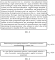
- FIG. 1 shows a method for determining a parameter value according to an embodiment of the present disclosure.
- the method shown in FIG. 1 may be performed by the user equipment in the sidelink communication. As shown in FIG. 1 , the method includes:
- a target numerical value of a target parameter at the current time is determined according to a target mode, where the target parameter includes at least one of an interference threshold, a signal strength threshold, a channel occupancy rate threshold, a channel busy rate threshold and a distance threshold, the target mode is at least one of the following:
- An effective time period of the target numerical value of the target parameter at the current time may be a time period between an effective time of the target numerical value and an effective time of a value of the target parameter at the next adjustment time.
- the counter in S110 may be applied to resource assignment.
- the target mode is to determine the target numerical value according to the target mapping relationship, where the first target information includes a target time length or a target time length ratio, the target time length includes a first time length or a second time length, the first time length is a time length between a timing start time and the current time, the second time length is a time length between the current time and the latest time meeting a transmission delay requirement, the user equipment does not perform information transmission within the first time length, and the target time length ratio is a ratio of a time length between the timing start time to the current start time to the delay requirement.
- the target mode is to determine the target numerical value according to the target mapping relationship and the first target information includes the target time length
- whether the current time is a parameter adjustment time may be determined according to an adjustment time granularity, or whether the current time is the parameter adjustment time may be determined according to the target time length and a preset time length.
- the latest time meeting the transmission delay requirement may also be understood as a time when the user equipment determines de-packet, or may be understood that a time interval between the latest time and a generation time of the data packet is the transmission delay requirement.
- the target parameter is an interference measurement threshold or a signal strength threshold as an example.
- the first time length is t
- the second time length res_t L-t
- a mapping relationship (the mapping relationship may be a table) between the interference measurement threshold or the signal strength threshold and the first time length or the second time length may be pre-defined or pre-configured.
- the current time is an adjustment time of the interference measurement threshold or the signal strength threshold
- a value of the interference measurement threshold or the signal strength threshold may be determined according to the value of t or res_t at the current time and the mapping relationship.
- the adjustment time granularity may be one of the following granularities: millisecond (ms), a subframe (subframe), N slots (slot), multi-slot (multi-slot), N symbols (symbol), a frame (frame) and a time-pattern (Time Pattern), where N is a positive integer greater than or equal to 1.
- the target parameter is a channel occupancy rate threshold or a channel busy rate threshold and the first target information includes a value of a counter (counter) as an example.
- a mapping relationship (the mapping relationship may be table) between the channel occupancy rate threshold or the channel busy rate threshold and the value of the counter may be pre-defined or pre-configured.
- a value of the channel occupancy rate threshold or a value of the channel busy rate at each parameter adjustment time may be determined according to the value of the counter of the parameter adjustment time and the mapping relationship. In this example, whether the current time is a parameter adjustment time may be determined according to an adjustment time granularity.
- the target parameter is a distance threshold and the first target information includes the number of times of retransmission as an example.
- a mapping relationship between the distance threshold and the number of times of retransmission may be pre-defined or pre-configured.
- a value of the distance threshold may be determined according to the number of times of retransmission at the parameter adjustment time and the mapping relationship.
- whether the current time is a parameter adjustment time may be determined according to an adjustment time granularity. Initial transmission may be considered as that the corresponding number of times of retransmission is 0.
- the above distance threshold may be understood as a threshold of a distance between the user equipment and the user equipment. For example, if the number of times of retransmission corresponding to one parameter adjustment time is 0 and the value of the distance threshold is 1000 m, the user equipment considers resources occupied by other user equipment within 1000 m away from itself as occupied resources. If the number of times of retransmission corresponding to the next parameter adjustment time is 1 and the value of the distance threshold is 500 m, the user equipment considers resources occupied by other user equipment within 500 m away from itself as occupied resources.
- the target mode is to determine the target numerical value according to the initial value of the target parameter and the numerical value adjustment step length.
- the method shown in FIG. 1 further includes: an initial value of the target parameter is determined according to a mapping relationship between an initial value corresponding to the first target information and the value of the target parameter, and the first target information.
- the user equipment determines the target numerical value according to the initial value of the target parameter and the numerical value adjustment step length.
- the user equipment determines the target numerical value of the target parameter actually according to the value of the target parameter before the current time and the numerical value adjustment step length.
- the first target information includes a target time length, where the target time length includes a first time length or a second time length, the first time length is a time length between a timing start time and the current time, the second time length is a time length between the current time and the latest time meeting the transmission delay requirement, and the user equipment does not perform information transmission within the first time length.
- whether the current time is a parameter adjustment time may be determined according to an adjustment time granularity, or whether the current time is the parameter adjustment time may be determined according to the target time length and a preset time length.
- the timing start time here may be one of the following times: an arrival time of a data packet, an activation time of a counter, a reception time of third target information and a time indicated by the third target information.
- the third target information includes at least one of the following information: high-level signaling, DCI and SCI.
- the third target information includes at least one of the following information: high-level signaling, DCI, SR, BSR and SCI.
- the target parameter is a channel occupancy rate threshold or a channel busy rate threshold and the first target information includes a value of a counter (counter) as an example.
- a mapping relationship (the mapping relationship may be table) between the channel occupancy rate threshold or the channel busy rate threshold and the value of the counter may be pre-defined or pre-configured.
- An initial value of the channel occupancy threshold or the channel busy rate threshold may be determined according to the value of the counter at the arrival time of the data packet and the mapping relationship.
- the target parameter is a distance threshold and the first target information includes the number of times of retransmission as an example.
- a mapping relationship between the distance threshold and the number of times of retransmission may be pre-defined or pre-configured.
- An initial value of the distance threshold may be determined according to the mapping relationship and the number of times of retransmission 0.
- a numerical value adjustment step length may be further determined.
- the numerical value adjustment step length may be pre-configured, pre-defined, configured by the network device or configured by the user equipment.
- the numerical value adjustment step length may also be determined on the basis of the mapping relationship.
- the target parameter is an interference measurement threshold as an example.
- the first time length is t
- the second time length res_t L-t
- a mapping relationship between the interference measurement threshold and the first time length may be pre-defined or pre-configured
- the adjustment time granularity may be pre-defined or pre-configured as 1 slot.
- t is within [a, b]
- the numerical value adjustment step length is 3 dB
- t is within [b, c]
- the numerical value adjustment step length is 6 dB.
- the value of the interference threshold is the value of the interference threshold at the current time minus 6 dB.
- the first target information further includes a granularity of a frequency domain resource unit
- the numerical value adjustment step length is determined by the user equipment according to a mapping relationship between the granularity of the frequency domain resource unit and the numerical value adjustment step length.
- the numerical value adjustment step length is determined by the user equipment according to a mapping relationship between the number of times of retransmission and the numerical value adjustment step length.
- the retransmissions at different times correspond to different numerical value adjustment step lengths, which can balance reliability and system congestion.
- the above solution for determining the initial value and determining the numerical value adjustment step length according to the mapping relationship at least includes the following technical solutions: (1) the initial value of the target parameter is determined according to the initial value of the target time length, and the numerical value adjustment step length is determined according to the mapping relationship between the target time length and the numerical value adjustment step length; (2) the initial value of the target parameter is determined according to the initial value of the target time length, and the numerical value adjustment step length is determined according to the mapping relationship between the granularity of the frequency domain resource unit and the numerical value adjustment step length; (3) the initial value of the target parameter is determined according to the initial value of the target time length, and the numerical value adjustment step length is determined according to the mapping relationship between the number of times of retransmission and the numerical value adjustment step length; (4) the initial value of the target parameter is determined according to the initial value of the counter, and the numerical value adjustment step length is determined according to the mapping relationship between the target time length and the numerical value adjustment step length; (5) the initial value of the target parameter is determined according to the initial value
- a method for determining a parameter value may include the following steps:
- a value RSRP_thresh of the RSRP threshold is obtained according to the second time length, and the mapping relationship between the second time length and the value of the RSRP threshold.
- RSRP on resources where scheduling assignment (SA) is located may be measured. In a case that RSRP is greater than RSRP_thresh, the current TTI is considered to be occupied.
- Step 4 in a case that the current TTI is occupied, the value of the counter maintains unchanged, TTI+1; and in a case that the current TTI is not occupied, the value of the counter decreases progressively, TTI+1.
- Step 5 in a case that the value of the counter is less than or equal to 0, information is transmitted at the next available TTI, otherwise, the step 3 and the subsequent steps are performed.
- steps 1-5 do not limit the method steps, and the sequence of the above steps are specifically determined by a logical relationship between the steps.
- FIG. 2 shows a method for determining a parameter value according to another embodiment of the present disclosure.
- the method shown in FIG. 2 may be performed by the user equipment in the sidelink communication. As shown in FIG. 2 , the method includes:
- the occupation situation of the transmission resource corresponding to the current time may be determined according to at least one of the following modes:
- the occupation situation of the transmission resource is determined, where the SA information is used to schedule the transmission resource corresponding to the current time.
- SA is demodulated to obtain a business priority of the data packet.
- the obtained business priority is lower than the priority of to-be-transmitted business, it is determined that the transmission resource is not occupied.
- the occupation situation of the transmission resource corresponding to the current time is determined, where the SA information is used to schedule the transmission resource corresponding to the current time.
- RSSI received Signal Strength Indication
- the occupation situation of the transmission resource corresponding to the current time is determined, where the SA information is used to schedule the transmission resource corresponding to the current time; or according to the measurement information of the transmission resource indicated by the SA information, the occupation situation of the transmission resource corresponding to the current time is determined, where the SA information is used to schedule the transmission resource corresponding to the current time.
- RSRP of data indicated by SA is measured; and in a case that the RSRP is lower than a second threshold value, it is considered that the transmission resource is not occupied.
- the threshold value of the RSRP may be adjusted according to the method shown in FIG. 1 .
- the adjustment granularity of the value of the counter is a time domain adjustment granularity, or the adjustment granularity of the value of the counter is a time frequency domain adjustment granularity.
- the time domain adjustment granularity here may be one of slot, ms and time-pattern, the time domain granularity in the time frequency domain adjustment granularity is one of slot, ms and time-pattern, and the frequency domain granularity in the time frequency domain adjustment granularity is one of a sub-channel (sub-channel), a resource block (Resource Block, RB) and F resource block groups (Resource Block Group, RBG).
- sub-channel sub-channel
- RB resource block
- RBG Resource Block Group
- the method shown in FIG. 2 further includes: an initial value of the counter is determined.
- the step that the initial value is determined according to the QoS requirement and the first mapping relationship includes: the target initial value range of the initial value is determined according to the first mapping relationship; and the initial value is determined from the target initial value range according to first target information, where the first target information includes at least one of the following information: a geographic position of user equipment, a speed of the user equipment, a distance between the user equipment, a density of the user equipment within a preset area range, a bearing type, a business type, a size of a packet and an arrival rate of the packet.
- the arrival rate of the packet here may be understood as the generation frequency of the data packet.
- the value range of the initial value of the counter may be determined on the basis of the QoS requirement, and then one value is further selected from the initial value range according to the first target information to serve as the initial value of the counter.
- mapping relationship between the priority and the value range of the initial value of the counter is pre-configured, where the mapping relationship here may be a one-to-many, many-to-one or many-to-many mapping relationship.
- the value range of the initial value of the counter may be selected according to the configured priority, and then one value is randomly selected from the value range to serve as the initial value of the counter.
- the value range of the initial value of the counter is selected according to the configured priority, and then one value is selected according to ID of the user equipment or the geographical position of the user equipment to serve as the initial value of the counter; therefore, the initial values of the counters corresponding to different user equipment with the same priority may be different.
- the value range of the initial value of the counter is selected according to the configured priority, and then one value is selected from the value range based on the indication of DCI or SCI to serve as the initial value of the counter.
- the DCI or SCI may indicate the sequence number of the initial value of the counter in the value range, and may also directly indicate the initial value.
- the initial value is determined according to second target information and a second mapping relationship, where the second mapping relationship includes a mapping relationship between the second target information and the initial value, and the second target information includes at least one of the following information: a QoS requirement, a geographical position of user equipment, a speed of the user equipment, a distance between the user equipment, a density of the corresponding user equipment in a preset area range, a bearing type, a business type, a size of a packet and an arrival rate of the packet. That is, the initial value may be determined directly according to the mapping relationship between the second target information and the initial value.
- the initial value of each type of counter may be determined according to the above method for determining the initial value, and the initial value of each type of counter may be configured with different or same value, which is not limited by the embodiment of the present disclosure.
- the method for determining the parameter value according to the embodiments of the present disclosure is described above in detail with reference to FIG. 1 and FIG. 2 .
- the user equipment according to the embodiment of the present disclosure is described below in detail with reference to FIG. 3 .
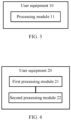
- FIG. 3 is a structural schematic diagram of user equipment according to an embodiment of the present disclosure.
- the user equipment shown in FIG. 3 is applied to sidelink communication.
- the user equipment 10 includes: a processing module, configured to: in a case that a current time is a parameter value adjustment time, determine a target numerical value of a target parameter at the current time according to a target mode, where the target parameter includes at least one of an interference threshold, a signal strength threshold, a channel occupancy rate threshold, a channel busy rate threshold and a distance threshold, the target mode is at least one of the following:
- the target mode is to determine the target numerical value according to the target mapping relationship, where the first target information includes a target time length or a target time length ratio, the target time length includes a first time length or a second time length, the first time length is a time length between a timing start time and the current time, the second time length is a time length between the current time and the latest time meeting the transmission delay requirement, the user equipment does not perform information transmission within the first time length, and the target time length ratio is a ratio of the time length between the timing start time and the current time to the delay requirement.
- the timing start time is one of the following times: an arrival time of a data packet, a reception time of second target information and a time indicated by the second target information; and in the case where the user equipment is a transmitting user equipment, the second target information includes at least one of the following information: high-level signaling, downlink control information (DCI) and sidelink control information (SCI).
- DCI downlink control information
- SCI sidelink control information
- the second target information includes at least one of the following information: high-level signaling, DCI, a scheduling request (SR), a buffer status report (BSR) and SCI.
- the target mode is to determine the target numerical value according to the initial value of the target parameter and the numerical value adjustment step length.
- the processing module 11 is further configured to: determine an initial value of the target parameter according to a mapping relationship between an initial value corresponding to the first target information and the value of the target parameter, and the first target information.
- the first target information includes a target time length, where the target time length includes a first time length or a second time length, the first time length is a time length between a timing start time and the current time, the second time length is a time length between the current time and the latest time meeting a transmission delay requirement, and the user equipment does not perform information transmission within the first time length.
- the third target information includes at least one of the following information: high-level signaling, DCI, SR, BSR and SCI.
- the processing module 11 is further configured to: according to an adjustment time granularity, determine whether the current time is a parameter adjustment time.
- the adjustment time granularity is determined by one of the following modes: pre-definition, pre-configuration, network device configuration and user equipment configuration.
- the processing module 11 is further configured to: according to the target time length and a preset time length, determine whether the current time is a parameter adjustment time.
- the numerical value adjustment step length is determined by the user equipment according to a mapping relationship between the target time length and the numerical value adjustment step length.
- the first target information further includes a granularity of a frequency domain resource unit
- the numerical value adjustment step length is determined by the user equipment according to a mapping relationship between the granularity of the frequency domain resource unit and the numerical value adjustment step length.
- the numerical value adjustment step length is determined by the user equipment according to a mapping relationship between the number of times of retransmission and the numerical value adjustment step length.
- the user equipment provided by the embodiment of the present disclosure can realize each process of implementing the user equipment in the embodiment of the method in FIG. 1 , which is not elaborated here to avoid repetition.
- FIG. 4 is a structural schematic diagram of user equipment according to another embodiment of the present disclosure.
- the user equipment shown in FIG. 4 is applied to sidelink communication.
- the user equipment 20 shown in FIG. 4 includes:
- the first processing module 21 is specifically configured to:
- the adjustment granularity of the value of the counter is a time domain adjustment granularity, or the adjustment granularity of the value of the counter is a time frequency domain adjustment granularity.
- the first processing module 21 is further configured to: determine an initial value of the counter.
- the first processing module 21 is specifically configured to: determine the initial value according to a quality of service (QoS) requirement and a first mapping relationship, where the first mapping relationship includes a mapping relationship between the QoS requirement and an initial value range.
- QoS quality of service
- the first processing module 21 is specifically configured to:
- the first processing module 21 is specifically configured to: determine the initial value according to second target information and a second mapping relationship, where the second mapping relationship includes a mapping relationship between the second target information and the initial value, and the second target information includes at least one of the following information: a QoS requirement, a geographical position of user equipment, a speed of the user equipment, a distance between the user equipment, a density of the user equipment within a preset area range, a bearing type, a business type, a size of a packet and an arrival rate of the packet.
- the user equipment provided by the embodiment of the present disclosure can realize each process of implementing the user equipment in the embodiment of the method in FIG. 2 , which is not elaborated here to avoid repetition.
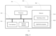
- the user interface 503 may include a display, a keyboard, a clicking device (for example: a mouse and a trackball (trackball)), a touch panel or a touchscreen.
- a clicking device for example: a mouse and a trackball (trackball)
- a touch panel for example: a touch panel or a touchscreen.
- RAMs may be used, for example, a static random access memory (Static RAM, SRAM), a dynamic random access memory (Dynamic RAM, DRAM), a synchronous dynamic random access memory (Synchronous DRAM, SDRAM), a double data rate synchronous dynamic random access memory (Double Data Rate SDRAM, DDRSDRAM), an enhanced synchronous dynamic random access memory (Enhanced SDRAM, ESDRAM), a synchlink dynamic random access memory (Synchlink DRAM, SLDRAM), and a direct rambus random access memory (Direct Rambus RAM, DRRAM).
- Static RAM, SRAM static random access memory
- DRAM dynamic random access memory
- DRAM synchronous dynamic random access memory
- SDRAM double data rate synchronous dynamic random access memory
- Double Data Rate SDRAM Double Data Rate SDRAM
- ESDRAM enhanced synchronous dynamic random access memory
- Synchlink DRAM synchlink dynamic random access memory
- SLDRAM direct rambus random access memory
- Direct Rambus RAM Direct Rambus RAM
- the operating system 5021 includes various system programs, such as a framework layer, a core library layer, and a driver layer, and is configured to implement various basic services and process hardware-based tasks.
- the application program 5022 includes various application programs, for example, a media player (Media Player) and a browser (Browser), and is configured to implement various application services.
- a program implementing the method in the embodiments of the present disclosure may be included in the application program 5022.
- the user equipment 500 further includes: a computer program which is stored in a memory 502 and executable on a processor 501, where the computer program, when being executed by a processor 501, enables the processor to implement each process of the method in FIG. 1 and FIG. 2 .
- a computer program which is stored in a memory 502 and executable on a processor 501, where the computer program, when being executed by a processor 501, enables the processor to implement each process of the method in FIG. 1 and FIG. 2 .
- the same technical effect can be achieved. In order to avoid repetition, details are not described herein again.
- the method disclosed in the embodiment of the present disclosure may be applied to the processor 501 or implemented by the processor 501.
- the processor 501 may be an integrated circuit chip having a signal processing capability. During implementation, the steps of the foregoing method may be completed by hardware integrated logic circuits in the processor 501 or instructions in a form of software.
- the above processor 501 may be a general-purpose processor, a digital signal processor (Digital Signal Processor, DSP), an application specific integrated circuit (Application Specific Integrated Circuit, ASIC), a field programmable gate array (Field Programmable Gate Array, FPGA) or other programmable logic devices, a discrete gate or transistor logic device, and a discrete hardware component.
- DSP Digital Signal Processor
- ASIC Application Specific Integrated Circuit
- FPGA Field Programmable Gate Array
- the processor may implement or perform the methods, the steps, and logical block diagrams that are disclosed in the embodiments of the present disclosure.
- the general-purpose processor may be a microprocessor or may be any conventional processor or the like.
- the steps of the method disclosed in the embodiments of the present disclosure may be directly performed by a hardware decoding processor or by a combination of hardware and software modules in the decoding processor.
- the software module may be located in a mature computer-readable storage medium in this field such as a random access memory, a flash memory, a read-only memory, a programmable read-only memory or an electrically erasable programmable memory, or a register.
- the computer-readable storage medium is located in the memory 502, and the processor 501 reads information from the memory 502 and completes the steps of the foregoing method in combination with hardware of the processor 501.
- the computer readable storage medium stores a computer program, and when the computer program is executed by the processor 501, the steps of the method embodiments shown in FIG. 1 to FIG. 2 are implemented.
- the embodiments described in the embodiments of the present disclosure may be implemented by hardware, software, firmware, middleware, microcode, or a combination thereof.
- the processing module may be implemented in one or more application specific integrated circuits (Application Specific Integrated Circuits, ASIC), a digital signal processor (Digital Signal Processor, DSP), a DSP device (DSP Device, DSPD), a programmable logic device (Programmable Logic Device, PLD), a field-programmable gate array (Field-Programmable Gate Array, FPGA), general processors, controllers, micro-controllers, micro-processors, and other electronic units for implementing the functions of the present disclosure, or their combinations.
- ASIC Application Specific Integrated Circuits
- DSP Digital Signal Processor
- DSP Device DSP Device
- DSPD programmable logic device
- PLD programmable Logic Device
- FPGA field-programmable gate array
- general processors controllers, micro-controllers, micro-processors, and other electronic units for implementing the functions
- technologies described in the embodiments of the present disclosure may be implemented by executing functional modules (for example, a process and a function) in the embodiments of the present disclosure.
- Software code can be stored in the memory and executed by the processor.
- the memory can be implemented inside or outside the processor.
- the embodiments of the present disclosure further provide a computer-readable storage medium.
- the computer-readable storage medium stores a computer program, and when a processor executes the computer program, the processes of the foregoing method embodiment are implemented and the same technical effect can be achieved. To avoid repetition, details are not described herein again.
- the computer readable storage medium is, for example, a read-only memory (Read-Only Memory, ROM for short), a random access memory (Random Access Memory, RAM for short), a magnetic disk, or an optical disk.
- the method in the foregoing embodiments may be implemented by software with a necessary general hardware platform.
- the method in the foregoing embodiments may also be implemented by hardware. However, in many cases, the former is a preferred implementation.
- the technical solutions of the present disclosure essentially or the part that contributes to the prior art may be embodied in the form of software products.
- the computer software product is stored in a storage medium (such as ROM/RAM, a magnetic disk and an optical disk), including several instructions for enabling one terminal (which may be a mobile phone, a computer, a server, an air conditioner, or a network device) to implement the method in each embodiment of the present disclosure.
Landscapes
- Engineering & Computer Science (AREA)
- Computer Networks & Wireless Communication (AREA)
- Signal Processing (AREA)
- Quality & Reliability (AREA)
- Mobile Radio Communication Systems (AREA)
- Compression, Expansion, Code Conversion, And Decoders (AREA)
- Testing, Inspecting, Measuring Of Stereoscopic Televisions And Televisions (AREA)
- Analogue/Digital Conversion (AREA)
Applications Claiming Priority (3)
| Application Number | Priority Date | Filing Date | Title |
|---|---|---|---|
| CN201910049780.1A CN111263469B (zh) | 2019-01-18 | 2019-01-18 | 确定参数值的方法和设备 |
| EP20741834.4A EP3914033B1 (fr) | 2019-01-18 | 2020-01-17 | Procédé et dispositif de détermination de valeur de paramètre |
| PCT/CN2020/072705 WO2020147825A1 (fr) | 2019-01-18 | 2020-01-17 | Procédé et dispositif de détermination de valeur de paramètre |
Related Parent Applications (2)
| Application Number | Title | Priority Date | Filing Date |
|---|---|---|---|
| EP20741834.4A Division EP3914033B1 (fr) | 2019-01-18 | 2020-01-17 | Procédé et dispositif de détermination de valeur de paramètre |
| EP20741834.4A Division-Into EP3914033B1 (fr) | 2019-01-18 | 2020-01-17 | Procédé et dispositif de détermination de valeur de paramètre |
Publications (2)
| Publication Number | Publication Date |
|---|---|
| EP4475593A2 true EP4475593A2 (fr) | 2024-12-11 |
| EP4475593A3 EP4475593A3 (fr) | 2025-01-22 |
Family
ID=70953779
Family Applications (2)
| Application Number | Title | Priority Date | Filing Date |
|---|---|---|---|
| EP24206992.0A Pending EP4475593A3 (fr) | 2019-01-18 | 2020-01-17 | Procédé et dispositif de détermination de valeur de paramètre |
| EP20741834.4A Active EP3914033B1 (fr) | 2019-01-18 | 2020-01-17 | Procédé et dispositif de détermination de valeur de paramètre |
Family Applications After (1)
| Application Number | Title | Priority Date | Filing Date |
|---|---|---|---|
| EP20741834.4A Active EP3914033B1 (fr) | 2019-01-18 | 2020-01-17 | Procédé et dispositif de détermination de valeur de paramètre |
Country Status (6)
| Country | Link |
|---|---|
| US (2) | US11979776B2 (fr) |
| EP (2) | EP4475593A3 (fr) |
| JP (2) | JP7203231B2 (fr) |
| CN (1) | CN111263469B (fr) |
| ES (1) | ES3001462T3 (fr) |
| WO (1) | WO2020147825A1 (fr) |
Families Citing this family (9)
| Publication number | Priority date | Publication date | Assignee | Title |
|---|---|---|---|---|
| US12438645B2 (en) * | 2019-05-05 | 2025-10-07 | Lenovo (Beijing) Limited | Sidelink data packet acknowledgment |
| CN113079355A (zh) * | 2021-03-29 | 2021-07-06 | 西安万像电子科技有限公司 | 图像传输方法和装置、存储介质及电子设备 |
| CN113098667B (zh) * | 2021-03-30 | 2023-06-23 | 联芸科技(杭州)股份有限公司 | 数据传输方法、系统、计算机设备和介质 |
| CN113079105B (zh) * | 2021-03-30 | 2023-03-24 | 联芸科技(杭州)股份有限公司 | 数据传输方法、系统、计算机设备和介质 |
| US11706596B2 (en) * | 2021-06-17 | 2023-07-18 | Ford Global Technologies, Llc | Vehicle roadside unit interference detection |
| CN117981456A (zh) * | 2021-09-28 | 2024-05-03 | 高通股份有限公司 | 用于自包含的用户装备间协调消息的资源选择 |
| CN113872733B (zh) * | 2021-09-29 | 2024-01-05 | 天翼物联科技有限公司 | 报文重发方法、装置、计算机设备及计算机可读存储介质 |
| CN115085771B (zh) * | 2022-08-23 | 2022-11-18 | 北京紫光青藤微系统有限公司 | 一种nfc信号的通道选择方法及装置 |
| CN117540588B (zh) * | 2024-01-10 | 2024-06-11 | 宁德时代新能源科技股份有限公司 | 电池仿真的时间步长调整方法、计算方法、装置及设备 |
Family Cites Families (19)
| Publication number | Priority date | Publication date | Assignee | Title |
|---|---|---|---|---|
| JP5134026B2 (ja) * | 2010-02-09 | 2013-01-30 | アンリツ株式会社 | 誤り率測定装置及び方法 |
| CN102164008B (zh) * | 2011-04-22 | 2013-11-27 | 华南理工大学 | 一种无控制信道的水下动态频谱接入方法 |
| KR101906867B1 (ko) * | 2011-09-27 | 2018-10-11 | 한양대학교 산학협력단 | 채널 상태를 이용한 적응적 채널 전송 장치 및 방법 |
| CN103052164B (zh) * | 2012-12-27 | 2016-02-24 | 北京邮电大学 | 蜂窝与d2d混合网络中终端直通通信的干扰控制协调方法 |
| JP6531765B2 (ja) * | 2015-01-30 | 2019-06-19 | 日本電気株式会社 | フラクショナルサブフレーム送信を実施する方法 |
| EP3284312B1 (fr) * | 2015-04-13 | 2020-06-03 | Telefonaktiebolaget LM Ericsson (publ) | Procédés de transmission conjointe de réseau étendu et liaison latérale pour équipement utilisateur permettant une communication de dispositif à dispositif |
| CN106470492B (zh) * | 2015-08-14 | 2020-07-07 | 中兴通讯股份有限公司 | 资源占用方法、装置及用户设备 |
| US11147044B2 (en) * | 2016-03-04 | 2021-10-12 | Lg Electronics Inc. | V2X transmission resource selecting method implemented by terminal in wireless communication system and terminal using same |
| EP3633906B1 (fr) | 2016-04-01 | 2024-05-08 | Motorola Mobility LLC | Procédé et appareil de programmation de transmissions de liaison montante à latence réduite |
| CN107509226A (zh) * | 2016-06-14 | 2017-12-22 | 屈银翔 | 一种有选择传输的路由寻址方法及装置 |
| CN107645774B (zh) * | 2016-07-20 | 2020-07-28 | 普天信息技术有限公司 | V2x网络中调度pc5口资源的确认方法 |
| CN109804683B (zh) * | 2016-08-11 | 2023-08-04 | Lg电子株式会社 | 在无线通信系统中终端向另一终端发送数据的方法 |
| CN107889158B (zh) * | 2016-09-29 | 2023-11-10 | 北京三星通信技术研究有限公司 | 传输控制和数据的方法及设备 |
| WO2018084608A2 (fr) * | 2016-11-03 | 2018-05-11 | Lg Electronics Inc. | Procédé de détermination de nombres de retransmissions de données de liaison latérale dans un système de communication sans fil, et dispositif correspondant |
| EP3536094B1 (fr) * | 2016-11-03 | 2022-08-31 | Panasonic Intellectual Property Corporation of America | Procédé, appareil et système de communication sans fil |
| CN108541017B (zh) | 2017-03-02 | 2023-04-28 | 中兴通讯股份有限公司 | 一种无线资源配置的方法及装置 |
| CN111149397B (zh) * | 2017-09-29 | 2023-09-29 | Lg电子株式会社 | 在无线通信系统中由终端发送v2x消息的方法和使用该方法的终端 |
| US10917180B2 (en) * | 2018-07-24 | 2021-02-09 | Comcast Cable Communications, Llc | Controlling vibration output from a computing device |
| US20200100284A1 (en) * | 2018-09-24 | 2020-03-26 | Samsung Electronics Co., Ltd. | Method and apparatus for contention window size adaptation of nr unlicensed |
-
2019
- 2019-01-18 CN CN201910049780.1A patent/CN111263469B/zh active Active
-
2020
- 2020-01-17 EP EP24206992.0A patent/EP4475593A3/fr active Pending
- 2020-01-17 ES ES20741834T patent/ES3001462T3/es active Active
- 2020-01-17 WO PCT/CN2020/072705 patent/WO2020147825A1/fr not_active Ceased
- 2020-01-17 EP EP20741834.4A patent/EP3914033B1/fr active Active
- 2020-01-17 JP JP2021540553A patent/JP7203231B2/ja active Active
-
2021
- 2021-07-15 US US17/376,444 patent/US11979776B2/en active Active
-
2022
- 2022-12-26 JP JP2022208391A patent/JP7585289B2/ja active Active
-
2024
- 2024-04-07 US US18/628,761 patent/US12432621B2/en active Active
Also Published As
| Publication number | Publication date |
|---|---|
| ES3001462T3 (en) | 2025-03-05 |
| EP3914033A1 (fr) | 2021-11-24 |
| WO2020147825A1 (fr) | 2020-07-23 |
| US20240251297A1 (en) | 2024-07-25 |
| US11979776B2 (en) | 2024-05-07 |
| CN111263469B (zh) | 2022-02-15 |
| JP7585289B2 (ja) | 2024-11-18 |
| US20210345180A1 (en) | 2021-11-04 |
| JP2022517027A (ja) | 2022-03-03 |
| CN111263469A (zh) | 2020-06-09 |
| US12432621B2 (en) | 2025-09-30 |
| EP3914033A4 (fr) | 2022-03-23 |
| EP3914033B1 (fr) | 2024-11-27 |
| JP7203231B2 (ja) | 2023-01-12 |
| JP2023052082A (ja) | 2023-04-11 |
| EP4475593A3 (fr) | 2025-01-22 |
Similar Documents
| Publication | Publication Date | Title |
|---|---|---|
| US12432621B2 (en) | Method and device for determining a parameter value | |
| CN111757403B (zh) | 一种资源配置方法及通信装置 | |
| US12177872B2 (en) | Resource allocation method and device | |
| CN111757509B (zh) | 一种数据传输方法及设备 | |
| EP4214983A1 (fr) | Aspects de synchronisation pour des messages d'informations d'assistance sl nr | |
| CN116113043B (zh) | 用于通信的方法及终端设备 | |
| US20230074305A1 (en) | Resource determining method, apparatus, and system | |
| US20240134715A1 (en) | Resource reselection method and apparatus, device, and storage medium | |
| US20260059526A1 (en) | Communication apparatus and communication method | |
| CN109314629B (zh) | 发送响应信息的方法、装置、存储介质以及电子设备 | |
| JP7771437B2 (ja) | サイドリンク通信方法および装置 | |
| CN119968913A (zh) | 通信网络中的资源指示 | |
| CN117041984A (zh) | 共享资源分配方法及装置 | |
| CN119485676A (zh) | 一种基于配置授权的通信方法及装置 | |
| JP2023546110A (ja) | 伝送リソース決定方法および装置 |
Legal Events
| Date | Code | Title | Description |
|---|---|---|---|
| PUAI | Public reference made under article 153(3) epc to a published international application that has entered the european phase |
Free format text: ORIGINAL CODE: 0009012 |
|
| STAA | Information on the status of an ep patent application or granted ep patent |
Free format text: STATUS: REQUEST FOR EXAMINATION WAS MADE |
|
| 17P | Request for examination filed |
Effective date: 20241016 |
|
| AC | Divisional application: reference to earlier application |
Ref document number: 3914033 Country of ref document: EP Kind code of ref document: P |
|
| AK | Designated contracting states |
Kind code of ref document: A2 Designated state(s): AL AT BE BG CH CY CZ DE DK EE ES FI FR GB GR HR HU IE IS IT LI LT LU LV MC MK MT NL NO PL PT RO RS SE SI SK SM TR |
|
| PUAL | Search report despatched |
Free format text: ORIGINAL CODE: 0009013 |
|
| AK | Designated contracting states |
Kind code of ref document: A3 Designated state(s): AL AT BE BG CH CY CZ DE DK EE ES FI FR GB GR HR HU IE IS IT LI LT LU LV MC MK MT NL NO PL PT RO RS SE SI SK SM TR |
|
| RIC1 | Information provided on ipc code assigned before grant |
Ipc: H04W 92/18 20090101ALN20241217BHEP Ipc: H04W 28/18 20090101ALN20241217BHEP Ipc: H04W 76/14 20180101ALI20241217BHEP Ipc: H04W 28/02 20090101AFI20241217BHEP |
|
| STAA | Information on the status of an ep patent application or granted ep patent |
Free format text: STATUS: EXAMINATION IS IN PROGRESS |
|
| 17Q | First examination report despatched |
Effective date: 20260227 |