EP4477142A1 - Verbesserte positionsverfolgung für einen ballonkatheter - Google Patents
Verbesserte positionsverfolgung für einen ballonkatheter Download PDFInfo
- Publication number
- EP4477142A1 EP4477142A1 EP24182140.4A EP24182140A EP4477142A1 EP 4477142 A1 EP4477142 A1 EP 4477142A1 EP 24182140 A EP24182140 A EP 24182140A EP 4477142 A1 EP4477142 A1 EP 4477142A1
- Authority
- EP
- European Patent Office
- Prior art keywords
- secondary catheter
- distal end
- catheter
- shaft
- expandable assembly
- Prior art date
- Legal status (The legal status is an assumption and is not a legal conclusion. Google has not performed a legal analysis and makes no representation as to the accuracy of the status listed.)
- Granted
Links
Images


Classifications
-
- A—HUMAN NECESSITIES
- A61—MEDICAL OR VETERINARY SCIENCE; HYGIENE
- A61B—DIAGNOSIS; SURGERY; IDENTIFICATION
- A61B18/00—Surgical instruments, devices or methods for transferring non-mechanical forms of energy to or from the body
- A61B18/04—Surgical instruments, devices or methods for transferring non-mechanical forms of energy to or from the body by heating
- A61B18/12—Surgical instruments, devices or methods for transferring non-mechanical forms of energy to or from the body by heating by passing a current through the tissue to be heated, e.g. high-frequency current
-
- A—HUMAN NECESSITIES
- A61—MEDICAL OR VETERINARY SCIENCE; HYGIENE
- A61M—DEVICES FOR INTRODUCING MEDIA INTO, OR ONTO, THE BODY; DEVICES FOR TRANSDUCING BODY MEDIA OR FOR TAKING MEDIA FROM THE BODY; DEVICES FOR PRODUCING OR ENDING SLEEP OR STUPOR
- A61M25/00—Catheters; Hollow probes
- A61M25/01—Introducing, guiding, advancing, emplacing or holding catheters
- A61M25/0105—Steering means as part of the catheter or advancing means; Markers for positioning
-
- A—HUMAN NECESSITIES
- A61—MEDICAL OR VETERINARY SCIENCE; HYGIENE
- A61B—DIAGNOSIS; SURGERY; IDENTIFICATION
- A61B18/00—Surgical instruments, devices or methods for transferring non-mechanical forms of energy to or from the body
- A61B18/04—Surgical instruments, devices or methods for transferring non-mechanical forms of energy to or from the body by heating
- A61B18/12—Surgical instruments, devices or methods for transferring non-mechanical forms of energy to or from the body by heating by passing a current through the tissue to be heated, e.g. high-frequency current
- A61B18/14—Probes or electrodes therefor
- A61B18/1492—Probes or electrodes therefor having a flexible, catheter-like structure, e.g. for heart ablation
-
- A—HUMAN NECESSITIES
- A61—MEDICAL OR VETERINARY SCIENCE; HYGIENE
- A61B—DIAGNOSIS; SURGERY; IDENTIFICATION
- A61B34/00—Computer-aided surgery; Manipulators or robots specially adapted for use in surgery
- A61B34/20—Surgical navigation systems; Devices for tracking or guiding surgical instruments, e.g. for frameless stereotaxis
-
- A—HUMAN NECESSITIES
- A61—MEDICAL OR VETERINARY SCIENCE; HYGIENE
- A61B—DIAGNOSIS; SURGERY; IDENTIFICATION
- A61B5/00—Measuring for diagnostic purposes; Identification of persons
- A61B5/06—Devices, other than using radiation, for detecting or locating foreign bodies ; Determining position of diagnostic devices within or on the body of the patient
- A61B5/061—Determining position of a probe within the body employing means separate from the probe, e.g. sensing internal probe position employing impedance electrodes on the surface of the body
- A61B5/062—Determining position of a probe within the body employing means separate from the probe, e.g. sensing internal probe position employing impedance electrodes on the surface of the body using magnetic field
-
- A—HUMAN NECESSITIES
- A61—MEDICAL OR VETERINARY SCIENCE; HYGIENE
- A61B—DIAGNOSIS; SURGERY; IDENTIFICATION
- A61B5/00—Measuring for diagnostic purposes; Identification of persons
- A61B5/24—Detecting, measuring or recording bioelectric or biomagnetic signals of the body or parts thereof
- A61B5/25—Bioelectric electrodes therefor
- A61B5/279—Bioelectric electrodes therefor specially adapted for particular uses
- A61B5/28—Bioelectric electrodes therefor specially adapted for particular uses for electrocardiography [ECG]
- A61B5/283—Invasive
- A61B5/287—Holders for multiple electrodes, e.g. electrode catheters for electrophysiological study [EPS]
-
- A—HUMAN NECESSITIES
- A61—MEDICAL OR VETERINARY SCIENCE; HYGIENE
- A61B—DIAGNOSIS; SURGERY; IDENTIFICATION
- A61B5/00—Measuring for diagnostic purposes; Identification of persons
- A61B5/24—Detecting, measuring or recording bioelectric or biomagnetic signals of the body or parts thereof
- A61B5/316—Modalities, i.e. specific diagnostic methods
- A61B5/318—Heart-related electrical modalities, e.g. electrocardiography [ECG]
-
- A—HUMAN NECESSITIES
- A61—MEDICAL OR VETERINARY SCIENCE; HYGIENE
- A61B—DIAGNOSIS; SURGERY; IDENTIFICATION
- A61B5/00—Measuring for diagnostic purposes; Identification of persons
- A61B5/68—Arrangements of detecting, measuring or recording means, e.g. sensors, in relation to patient
- A61B5/6846—Arrangements of detecting, measuring or recording means, e.g. sensors, in relation to patient specially adapted to be brought in contact with an internal body part, i.e. invasive
- A61B5/6847—Arrangements of detecting, measuring or recording means, e.g. sensors, in relation to patient specially adapted to be brought in contact with an internal body part, i.e. invasive mounted on an invasive device
- A61B5/6852—Catheters
- A61B5/6856—Catheters with a distal loop
-
- G—PHYSICS
- G06—COMPUTING OR CALCULATING; COUNTING
- G06T—IMAGE DATA PROCESSING OR GENERATION, IN GENERAL
- G06T17/00—Three-dimensional [3D] modelling for computer graphics
-
- A—HUMAN NECESSITIES
- A61—MEDICAL OR VETERINARY SCIENCE; HYGIENE
- A61B—DIAGNOSIS; SURGERY; IDENTIFICATION
- A61B18/00—Surgical instruments, devices or methods for transferring non-mechanical forms of energy to or from the body
- A61B2018/00315—Surgical instruments, devices or methods for transferring non-mechanical forms of energy to or from the body for treatment of particular body parts
- A61B2018/00345—Vascular system
- A61B2018/00351—Heart
-
- A—HUMAN NECESSITIES
- A61—MEDICAL OR VETERINARY SCIENCE; HYGIENE
- A61B—DIAGNOSIS; SURGERY; IDENTIFICATION
- A61B18/00—Surgical instruments, devices or methods for transferring non-mechanical forms of energy to or from the body
- A61B2018/00571—Surgical instruments, devices or methods for transferring non-mechanical forms of energy to or from the body for achieving a particular surgical effect
- A61B2018/00577—Ablation
-
- A—HUMAN NECESSITIES
- A61—MEDICAL OR VETERINARY SCIENCE; HYGIENE
- A61B—DIAGNOSIS; SURGERY; IDENTIFICATION
- A61B18/00—Surgical instruments, devices or methods for transferring non-mechanical forms of energy to or from the body
- A61B2018/00571—Surgical instruments, devices or methods for transferring non-mechanical forms of energy to or from the body for achieving a particular surgical effect
- A61B2018/00595—Cauterization
-
- A—HUMAN NECESSITIES
- A61—MEDICAL OR VETERINARY SCIENCE; HYGIENE
- A61B—DIAGNOSIS; SURGERY; IDENTIFICATION
- A61B18/00—Surgical instruments, devices or methods for transferring non-mechanical forms of energy to or from the body
- A61B2018/00571—Surgical instruments, devices or methods for transferring non-mechanical forms of energy to or from the body for achieving a particular surgical effect
- A61B2018/00613—Irreversible electroporation
-
- A—HUMAN NECESSITIES
- A61—MEDICAL OR VETERINARY SCIENCE; HYGIENE
- A61B—DIAGNOSIS; SURGERY; IDENTIFICATION
- A61B18/00—Surgical instruments, devices or methods for transferring non-mechanical forms of energy to or from the body
- A61B18/04—Surgical instruments, devices or methods for transferring non-mechanical forms of energy to or from the body by heating
- A61B18/12—Surgical instruments, devices or methods for transferring non-mechanical forms of energy to or from the body by heating by passing a current through the tissue to be heated, e.g. high-frequency current
- A61B18/1206—Generators therefor
- A61B2018/1246—Generators therefor characterised by the output polarity
- A61B2018/1253—Generators therefor characterised by the output polarity monopolar
-
- A—HUMAN NECESSITIES
- A61—MEDICAL OR VETERINARY SCIENCE; HYGIENE
- A61B—DIAGNOSIS; SURGERY; IDENTIFICATION
- A61B18/00—Surgical instruments, devices or methods for transferring non-mechanical forms of energy to or from the body
- A61B18/04—Surgical instruments, devices or methods for transferring non-mechanical forms of energy to or from the body by heating
- A61B18/12—Surgical instruments, devices or methods for transferring non-mechanical forms of energy to or from the body by heating by passing a current through the tissue to be heated, e.g. high-frequency current
- A61B18/1206—Generators therefor
- A61B2018/1246—Generators therefor characterised by the output polarity
- A61B2018/126—Generators therefor characterised by the output polarity bipolar
-
- A—HUMAN NECESSITIES
- A61—MEDICAL OR VETERINARY SCIENCE; HYGIENE
- A61B—DIAGNOSIS; SURGERY; IDENTIFICATION
- A61B18/00—Surgical instruments, devices or methods for transferring non-mechanical forms of energy to or from the body
- A61B18/04—Surgical instruments, devices or methods for transferring non-mechanical forms of energy to or from the body by heating
- A61B18/12—Surgical instruments, devices or methods for transferring non-mechanical forms of energy to or from the body by heating by passing a current through the tissue to be heated, e.g. high-frequency current
- A61B18/14—Probes or electrodes therefor
- A61B2018/1467—Probes or electrodes therefor using more than two electrodes on a single probe
-
- A—HUMAN NECESSITIES
- A61—MEDICAL OR VETERINARY SCIENCE; HYGIENE
- A61B—DIAGNOSIS; SURGERY; IDENTIFICATION
- A61B34/00—Computer-aided surgery; Manipulators or robots specially adapted for use in surgery
- A61B34/20—Surgical navigation systems; Devices for tracking or guiding surgical instruments, e.g. for frameless stereotaxis
- A61B2034/2046—Tracking techniques
- A61B2034/2051—Electromagnetic tracking systems
-
- A—HUMAN NECESSITIES
- A61—MEDICAL OR VETERINARY SCIENCE; HYGIENE
- A61B—DIAGNOSIS; SURGERY; IDENTIFICATION
- A61B34/00—Computer-aided surgery; Manipulators or robots specially adapted for use in surgery
- A61B34/20—Surgical navigation systems; Devices for tracking or guiding surgical instruments, e.g. for frameless stereotaxis
- A61B2034/2046—Tracking techniques
- A61B2034/2059—Mechanical position encoders
-
- A—HUMAN NECESSITIES
- A61—MEDICAL OR VETERINARY SCIENCE; HYGIENE
- A61B—DIAGNOSIS; SURGERY; IDENTIFICATION
- A61B5/00—Measuring for diagnostic purposes; Identification of persons
- A61B5/24—Detecting, measuring or recording bioelectric or biomagnetic signals of the body or parts thereof
- A61B5/316—Modalities, i.e. specific diagnostic methods
- A61B5/318—Heart-related electrical modalities, e.g. electrocardiography [ECG]
- A61B5/367—Electrophysiological study [EPS], e.g. electrical activation mapping or electro-anatomical mapping
Definitions
- the present disclosure relates generally to invasive medical catheters, and particularly to cardiac catheters.
- U.S. Patent 8,478,379 describes a method for visualization of a probe that includes receiving an input indicative of respective apparent coordinates of a plurality of points disposed along a length of the probe inside a body of a subject, and applying a model of known mechanical properties of the probe to the apparent coordinates so as to compute a cost function with respect to shapes that can be assumed by the probe in the body.
- a shape is chosen responsively to the cost function, and corrected coordinates of the points along the length of the probe are generated based on the shape.
- the representation of the probe using the corrected coordinates is then displayed.
- U.S. Patent 8,478,383 describes a method including receiving an input indicative of respective apparent locations of a plurality of points disposed along a length of a probe inside a body of a subject, and applying a model of known mechanical properties of the probe to the respective apparent locations so as to minimize a first cost function with respect to shapes that can be assumed by the probe in the body.
- the method further includes choosing a shape responsively to the minimized first cost function and determining preliminary coordinates of the apparent locations responsively to the shape, minimizing a second cost function with respect to differences between the apparent locations and the preliminary coordinates, and generating corrected coordinates of the points along the length of the probe based on the minimized second cost function.
- the primary catheter includes a distal end assembly that is expandable, such as a balloon assembly.
- An exmaple elaborated below of a secondary catheter is a lasso shaped catheter.
- the lasso shaped catheter is advanced distally coaxially through the expandable balloon assembly.
- the physician may operate an expandable assembly with the secondary catheter.
- the secondary catheter helps to guide the expandable assembly to a desired location for treatment or diagnosis.
- the secondary catheter also called “a guiding catheter”
- the secondary catheter is more flexible and less bulky than the expandable assembly. This makes it easier and safer to maneuver within a heart chamber.
- the expandable assembly can be directed to that location.
- the secondary catheter typically includes a plurality of second position sensors at its distal end, e.g., 3 single axis sensors (SAS) that are magnetic based sensors.
- SAS single axis sensors
- the secondary catheter further includes a plurality of electrodes.
- the distal end of the secondary catheter is curved, e.g., lasso shaped in its expanded shape.
- the expandable assembly is deployed and expanded at vicinity to the desired location. It is important to be able to track the locations of the electrodes so the physician can determine where the ablation will occur or where on tissue EP signals are captured.
- the expandable assembly may deflect.
- the position of the electrodes on the balloon can be significantly different due to the deflection as compared to their position without deflection.
- the positioning of the electrodes on the expandable assembly cannot therefore be inferred from the TAS on the distal end of the shaft. This is because the TAS at the distal end of the shaft does not provide any information regarding the deflection of the balloon with respect to the shaft.
- the disclosed examples use the position sensors on the secondary catheter to track the deflection of the expandable assembly.
- the disclosed tracking technique is further based on modeling the mechanical properties of a portion of the primary catheter and on using position signals to solve the model to estimate orientation of the expandable assembly.
- the disclosed technique visualizes the shape of the secondary catheter to a user as it changes in time due to a medical procedure (e.g., due to a physician manipulating the expandable assembly) and the motion of the beating heart.
- the deflection of the expandable assembly with respect to the shaft is determined based on the shape of the secondary catheter.
- techniques to position-track an expandable assembly coupled at a distal end of a shaft inside an organ are provided.
- the tracking and visualization are provided while the expandable assembly may bend with respect to the shaft.
- a model is provided that extends the catheter mechanics algorithm provided in the aforementioned U.S. Patent 8,478,379 , to use non-fixed location sensors (not fixed to a modeled portion of the primary catheter) so they can slide relative to the primary catheter.
- the sensors are fixed to the secondary catheter.
- a secondary catheter section inside a rigid tube within the balloon is expected to remain nearly straight do to the relatively small diameter of the tube. This is modeled by increasing the rigidity property of this section in the mechanical model. The rigidity property determines how much the cost function increases when bending this section. High rigidity results in a high-cost function value, so after cost minimization this section tends to remain nearly straight.
- the degree at which the model allows the secondary catheter to bend within the tube is defined by the relative diameter of the tube with respect to the secondary catheter.
- a model is provided of a lasso catheter including three SASs.
- a proximal magnetic based position sensor e.g., a (TAS)
- TAS proximal magnetic based position sensor
- the lasso has a nearly straight proximal base portion and a curved distal portion that forms a lasso shape.
- the three free parameters (to be determined), as specified in US Patent No. 8,478,379 , of a cost function of the disclosed model represent the position, the orientation, and the shape of the secondary catheter and the position of the TAS sensor relative to some predetermined position.
- a new free parameter the length of the portion of the secondary catheter the slid distally past the TAS, in addition to the parameters in US Patent No. 8,478,379 represents the displacement of the TAS sensor relative to some predetermined position (for example - one of the SAS positions).
- the cost function is minimized with respect to all free parameters giving the position, orientation and shape of the secondary catheter secondary catheter which best fits all sensor measurements and the catheter mechanical properties.
- the catheter mechanics algorithm framework is used to interpolate between the measure location over the secondary catheter (in one exmaple, the secondary catheter is a lasso catheter) to obtain its shape.
- the estimated shape of the secondary catheter extending through the balloon and the positions of the position sensors mounted on the secondary catheter may be used to estimate and/or predict the balloon orientation and/or deflection instead of working under the assumption of no balloon deflection.
- the processor estimates the balloon position and orientation. To this end, the processor uses the TAS sensor's known location at the base of the balloon, along with the fact that the lasso secondary catheter extends through the central distal edge of the balloon.
- the estimation is even more accurate, since the interpolated part of the lasso secondary catheter secondary catheter contains at least one SAS inside the assembly.
- Fig. 1 is a schematic, pictorial illustration of a catheter-based electrophysiology (EP) mapping and ablation system 10, in accordance with an example of the present disclosure.
- EP electrophysiology
- System 10 includes multiple catheters, which are percutaneously inserted by physician 24 through the patient's vascular system into a chamber or vascular structure of a heart 12.
- a delivery sheath 28 catheter is inserted into the left or right atrium near a desired location in heart 12. Thereafter, a plurality of catheters can be inserted into delivery sheath 28 so as to arrive at the desired location.
- a balloon catheter 14 is shown inserted via sheath 28 using a shaft 22 into a left atrium 46 of a heart 12.
- the plurality of catheters may include catheters dedicated for sensing intracardiac electrograms (IEGM) and/or for both sensing and ablating, as well as imaging catheters.
- An example balloon catheter 14 that is configured for sensing IEGM and to perform electrical ablation is illustrated herein.
- physician 24 brings an expandable (e.g., balloon) assembly 44 fitted on shaft 22 of catheter 14 into contact with the heart wall for ablating a target site in heart 12, such as an ostium 47 of a pulmonary vein.
- a secondary catheter secondary catheter 40 having a section that has assumed a pre-shaped form of a lasso catheter is passed distally to the balloon via a hollow channel inside expandable assembly 44 (channel shown in Fig. 2 ).
- the secondary catheter secondary catheter is used to guide and position the balloon at ostium 47 of the pulmonary vein.
- the spiral portion of the secondary catheter secondary catheter comprises a plurality of sensing electrodes disposed thereon (not shown) for acquiring IEGM around the wall of the pulmonary vein in the vicinity of the ostium.
- balloon catheter 14 is an exemplary catheter that includes one, and preferably multiple, electrodes 26 distributed evenly over a circumference of expandable assembly 44 and configured to sense the IEGM signals and perform ablation.
- Catheter 14 additionally includes (i) a secondary catheter secondary catheter 40 configured to assume a pre-shape of a lasso catheter when advanced distally of expandable assembly 44, the secondary catheter secondary catheter having a generally curved base portion (which can be straight in a blood pool) and a lasso spiral portion, (ii) three magnetic position sensors 128 disposed over a distal end of secondary catheter secondary catheter 40, and (iii) a proximal position sensor 29 disposed over a distal end 41 of shaft 22 near expandable assembly 44 for tracking a position of distal end 41 of shaft 22 and for tracking the orientation of the distal end of shaft 22.
- Magnetic-based position sensors 29 and 128, which are further described in Fig. 2 may be operated together with a location pad 25 including a plurality of magnetic coils 32 configured to generate magnetic fields in a predefined working volume. Details of the magnetic-based position-sensing technology are described in U.S. Patent Nos. 5,5391,199 ; 5,443,489 ; 5,558,091 ; 6,172,499 ; 6,239,724 ; 6,332,089 ; 6,484,118 ; 6,618,612 ; 6,690,963 ; 6,788,967 ; 6,892,091 .
- System 10 includes one or more electrode patches 38 positioned for skin contact on patient 23 to establish location references for location pad 25 as well as impedance-based tracking functionality of electrodes 26.
- impedance-based tracking electrical current is directed toward electrodes 26 and sensed at electrode skin patches 38 so that the location of each electrode can be triangulated via electrode patches 38. Details of the impedance-based location-tracking technology are described in US Patent Nos. 7,536,218 ; 7,756,576 ; 7,848,787 ; 7,869,865 ; and 8,456,182 .
- a recorder 11 displays electrograms 21 captured with body surface ECG electrodes 18 and intracardiac electrograms (IEGM) captured with electrodes 26 of catheter 14.
- Recorder 11 may include pacing capability for pacing the heart rhythm and/or may be electrically connected to a standalone pacer.
- System 10 may include an ablation energy generator 50 that is adapted to conduct ablative energy to one or more electrodes at a distal tip of a catheter configured for ablation.
- Energy produced by ablation energy generator 50 may include, but is not limited to, radiofrequency (RF) energy or pulsed-field ablation (PFA) energy, including monopolar or bipolar high-voltage DC pulses as may be used to affect irreversible electroporation (IRE), or combinations thereof.
- RF radiofrequency
- PFA pulsed-field ablation
- IRE irreversible electroporation
- Patient interface unit (PIU) 30 is an interface configured to establish electrical communication between catheters, electrophysiological equipment, power supply and a workstation 55 for controlling system 10 operation.
- Electrophysiological equipment of system 10 may include, for example, multiple catheters, location pad 25, body surface ECG electrodes 18, electrode patches 38, ablation energy generator 50, and recorder 11.
- PIU 30 additionally includes processing capability for implementing real-time computations of catheter locations and for performing ECG calculations.
- Workstation 55 includes a processor 56 unit with a memory 57, or storage with appropriate operating software loaded therein, and user interface capability. Workstation 55 may provide multiple functions, optionally including (i) modeling endocardial anatomy in three-dimensions (3D) and rendering the model or anatomical map 20 for display on a display device 27, (ii) displaying on display device 27 activation sequences (or other data) compiled from recorded electrograms 21 in representative visual indicia or imagery superimposed on the rendered anatomical map 20, (iii) displaying real-time locations and orientations of multiple catheters within the heart chamber, and (iv) displaying on display device 27 sites of interest such as places where ablation energy has been applied.
- One commercial product embodying elements of system 10 is available as the CARTO TM 3 System, available from Biosense Webster, Inc., 31A Technology Drive, Irvine, CA 92618.
- an example of a primary catheter is a balloon catheter.
- An example of a secondary catheter is a lasso shaped catheter. As described above, the lasso shaped catheter is coaxially extended through the expandable balloon assembly.
- the disclosed technique purpose is to track orientation (or the deflection) of the expandable assembly with respect to its shaft. Two examples are discussed:
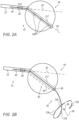
- Figs. 2A and 2B are schematic pictorial illustrations of the primary catheter 14 and a secondary catheter 40 extending therethrough the primary catheter 14 of Fig. 1 at two deployment states of the, in accordance with examples of the present disclosure.
- Primary catheter 14 includes an expandable balloon assembly 44, while secondary catheter 40 is lasso shaped catheter 40.
- the orientation of balloon assembly 44 without forces exerted on it is given by a longitudinal axis 62, where longitudinal axis 62 is defined as the orientation parallel to the distal end portion 41 of shaft 22. Axis 62 orientation is thus known from TAS 29.
- balloon 44 may be deflected and oriented off axis 62, e.g., along a deflected orientation 64 relative to that of the distal end 41 of shaft 22.
- secondary catheter secondary catheter 40 is seen partially advanced via shaft 22, e.g., only to a point where the secondary catheter secondary catheter is still fully inside a hollow channel 217 of expandable assembly 44.
- secondary catheter secondary catheter 40 is fully advanced via shaft 22 so that the distal end of secondary catheter secondary catheter 40 is fully deployed distally of expandable balloon assembly 44 and has regained its pre-shaped lasso form.
- Catheter 14 includes a TAS 29 disposed on shaft 22 of the balloon catheter.
- processor 56 tracks the position and orientation of the distal end of the shaft in three dimensions (3D).
- processor 56 can determine an orientation of longitudinal axis 62 in the 3D coordinate system defined by location pad 25.
- the balloon catheter additionally includes a lasso secondary catheter fitted through the axis of the balloon.
- the lasso catheter 82 includes one or more electrodes that may be used for capturing electrophysiological (EP) signals in the heart chamber.
- the lasso mapping catheter includes three SASs 128 to track positions of, for example, electrodes 129 fitted on the lasso (e.g., such as described in U.S. Patent Application Publication 2021/0001084 , which is assigned to the assignee of the current application).
- the deflection is schematically shown as an orientation 64 that is largely parallel to a longitudinal axis along rigid channel 217.
- secondary catheter secondary catheter 40 is largely straight.
- One or more SAS are known to be inside the balloon, based on the estimated distance between the SAS positions and TAS 29 as compared to the known length of rigid channel 217. The amount of balloon deflection is deduced from the deflection of secondary catheter secondary catheter 40 inside rigid channel 217 using readings from TAS 29 and SASs 128.
- section 80 of secondary catheter secondary catheter 40 which is inside balloon 44, is straight along a to-be-determined deflected orientation 64.
- a typically curved distal section 82 is located between a distal tip (e.g., distal pole of a balloon having sphere shape) 65 of the balloon and an estimated average position 66 of a center point of the lasso.
- Position 66 and orientation 68 (i.e., orientation 58) at position 66 are estimated from signals provided by SASs 128 when deployed in the lasso configuration.
- Orientation 64 is deduced using the model described using Fig. 3 below that is applied to the entire secondary catheter secondary catheter based on output from TAS 29 and each of SAS sensors 128. A centroid 66 of position of SASes 128 is estimated.
- Fig. 3 is a schematic illustration of a model 360 geometry of a secondary catheter such as of Fig. 2 , in accordance with an example of the present disclosure.
- points E 0 , E 1 , E 2 and E 3 represent calculated locations of position sensors based on the measured locations of points M 0 , M 1 , M 2 and M 3 .
- M 0 data point is from the TAS 29 that is not fixed to the secondary catheter, while data points M 1 -M 3 are from the SAS 128.
- the model thus calculates points E1, E2 and E3 (inferred from the measurements) that are assumed fixed to the shaft while point E0 can slide on the shaft.
- Model 630 comprises straight rigid sections 362, 364 and 366, connected by joints 368 and 370 that allow rotation (bending and twisting).
- the position of section 362 is described by position matrix x 0 , and the orientation of section 62 is given by a matrix ⁇ 0 .
- Orientation matrix ⁇ 0 is a local reference frame of section 362 with its ⁇ circumflex over (x) ⁇ and ⁇ axes being perpendicular to section 362, and the ⁇ circumflex over (z) ⁇ axis pointing along section 362.
- Section 364 starts at the end of section 362 (i.e., via connecting joint 368), and its orientation is given by matrix ⁇ 1 .
- Section 366 starts at the end of section 364 (i.e., via connecting joint 370), and its orientation is given by matrix ⁇ 2 .
- model geometry 360 comprises three sections, alternative model geometries may comprise either fewer than three or more than three sections.
- position vector x 0 and the orientation matrix ⁇ 0 relate to TAS 29 and orientation 62, respectively.
- Position vector x 3 and the orientation matrix ⁇ 3 relate to average position 66 and orientation 68, respectively, calculated from SASs 128 signals.
- Position vector x 2 and the orientation matrix ⁇ 2 measurements are absent and are weighted zero in the relevant equation below.
- the secondary catheter physical properties that affect its shape are defined by the parameters ⁇ N, L k , G k (d), P k , and S ⁇ wherein:
- the physical properties of the secondary catheter are described by parameters ⁇ A k , B k ⁇ which represent the resistance (e.g., stiffness or rigidity) of a joint between section k and section (k-1) against bending and twisting, respectively.
- the processor applies a cost function to calculate the quality of the match between the primary catheter model and received position data.
- This match defines the shape of the primary catheter with the lowest cost according to the model, which in turn gives corrected coordinates of the points along the length of the secondary catheter that correspond to the locations of the position transducers.
- the secondary catheter state as determined by the processor, describes its location and shape and its deflection values. The state is given by the variables ⁇ x 0 , r k , d ⁇ :
- the processor applies a minimization algorithm to the cost function in order to find a minimal cost primary catheter state that achieves a minimum value of the cost function (i.e., a best match).
- the processor then calculates a position error score, which represents the position error between the locations of the position transducers given by the primary catheter model and state, and the actual measurements.
- ⁇ ⁇ int , ⁇ pos , ⁇ or ⁇ describe the relative importance of deviation of the secondary catheter from its free shape vs. the position and orientation errors.
- the physician manipulates the catheter to bring the electrodes mounted on the distal portion of the basket assembly into firm contact with tissue, so as to ablate target tissue (e.g., an ostium of a pulmonary vein).
- target tissue e.g., an ostium of a pulmonary vein.
- a primary catheter visualization step 408 after determining the minimal cost primary catheter state, the processor presents a map of a cardiac cavity on display 27, showing the position and orientation of balloon 44 inside the cavity.
- a system (10) includes a secondary catheter (40), a primary catheter (14), and a processor (56).
- the primary catheter (14) includes (i) a shaft (22) for insertion into an organ of a patient, (ii) a first position sensor (29) disposed on a distal end of the shaft, (iii) an expandable assembly (44) coupled at the distal end of the shaft (22), the expandable assembly (44) comprising a hollow channel (217) to allow passage of the secondary catheter (40) distally via the expandable assembly (44), and (iv) a plurality of second position sensors (128) disposed along a distal end of the secondary catheter (40), which are configured to indicate a respective plurality of positions along the distal end of the secondary catheter (40).
- the processor (56) is configured to (i) receive the indications of the plurality of positions, (ii) apply a model of known mechanical properties of the distal end of the secondary catheter (40) to the plurality of positions to compute a bending profile of the secondary catheter (40) inside the expandable assembly (44), and (iii) based on the computed bending profile, estimate an orientation of the expandable assembly (44) with respect to the distal end of the shaft (22) .
- model of known mechanical properties of the secondary catheter (40) comprises (i) multiple sections (362, 364, 366) of the secondary catheter (40), (ii) a length of each of the sections, (iii) a rotation matrix defining relative rotation of each of the sections with regard to a preceding section, and (iv) the plurality of positions on the secondary catheter (40) .
- a method includes receiving indications of a plurality of positions from a first position sensor (29) disposed on a distal end of a shaft (22) for insertion into an organ of a patient, the distal end of the shaft (22) is coupled with an expandable assembly (44) comprising a hollow channel (217) to allow passage of a secondary catheter (40) distally via the expandable assembly (44), and from a plurality of second position sensors (128) disposed along a distal end of the secondary catheter (40).
- a model of known mechanical properties of the distal end of the secondary catheter (40) is applied to the plurality of positions to compute a bending profile of the secondary catheter (40) inside the expandable assembly (44). Based on the computed bending profile, an orientation is estimated of the expandable assembly (44) with respect to the distal end of the shaft (22).
Landscapes
- Health & Medical Sciences (AREA)
- Life Sciences & Earth Sciences (AREA)
- Engineering & Computer Science (AREA)
- Surgery (AREA)
- Physics & Mathematics (AREA)
- Public Health (AREA)
- General Health & Medical Sciences (AREA)
- Biomedical Technology (AREA)
- Heart & Thoracic Surgery (AREA)
- Veterinary Medicine (AREA)
- Animal Behavior & Ethology (AREA)
- Medical Informatics (AREA)
- Molecular Biology (AREA)
- Biophysics (AREA)
- Pathology (AREA)
- Cardiology (AREA)
- Nuclear Medicine, Radiotherapy & Molecular Imaging (AREA)
- Human Computer Interaction (AREA)
- Plasma & Fusion (AREA)
- Otolaryngology (AREA)
- Software Systems (AREA)
- Computer Graphics (AREA)
- Geometry (AREA)
- General Physics & Mathematics (AREA)
- Theoretical Computer Science (AREA)
- Pulmonology (AREA)
- Anesthesiology (AREA)
- Hematology (AREA)
- Robotics (AREA)
- Physiology (AREA)
- Media Introduction/Drainage Providing Device (AREA)
- Surgical Instruments (AREA)
- Measurement And Recording Of Electrical Phenomena And Electrical Characteristics Of The Living Body (AREA)
Applications Claiming Priority (1)
| Application Number | Priority Date | Filing Date | Title |
|---|---|---|---|
| US202363521206P | 2023-06-15 | 2023-06-15 |
Publications (2)
| Publication Number | Publication Date |
|---|---|
| EP4477142A1 true EP4477142A1 (de) | 2024-12-18 |
| EP4477142B1 EP4477142B1 (de) | 2026-03-11 |
Family
ID=91580667
Family Applications (1)
| Application Number | Title | Priority Date | Filing Date |
|---|---|---|---|
| EP24182140.4A Active EP4477142B1 (de) | 2023-06-15 | 2024-06-14 | Verbesserte positionsverfolgung für einen ballonkatheter |
Country Status (5)
| Country | Link |
|---|---|
| US (1) | US12447311B2 (de) |
| EP (1) | EP4477142B1 (de) |
| JP (1) | JP2024180364A (de) |
| CN (1) | CN119138998A (de) |
| IL (1) | IL313002A (de) |
Citations (18)
| Publication number | Priority date | Publication date | Assignee | Title |
|---|---|---|---|---|
| US5391199A (en) | 1993-07-20 | 1995-02-21 | Biosense, Inc. | Apparatus and method for treating cardiac arrhythmias |
| US5558091A (en) | 1993-10-06 | 1996-09-24 | Biosense, Inc. | Magnetic determination of position and orientation |
| US6172499B1 (en) | 1999-10-29 | 2001-01-09 | Ascension Technology Corporation | Eddy current error-reduced AC magnetic position measurement system |
| US6239724B1 (en) | 1997-12-30 | 2001-05-29 | Remon Medical Technologies, Ltd. | System and method for telemetrically providing intrabody spatial position |
| US6332089B1 (en) | 1996-02-15 | 2001-12-18 | Biosense, Inc. | Medical procedures and apparatus using intrabody probes |
| US6484118B1 (en) | 2000-07-20 | 2002-11-19 | Biosense, Inc. | Electromagnetic position single axis system |
| US6618612B1 (en) | 1996-02-15 | 2003-09-09 | Biosense, Inc. | Independently positionable transducers for location system |
| US6690963B2 (en) | 1995-01-24 | 2004-02-10 | Biosense, Inc. | System for determining the location and orientation of an invasive medical instrument |
| US6892091B1 (en) | 2000-02-18 | 2005-05-10 | Biosense, Inc. | Catheter, method and apparatus for generating an electrical map of a chamber of the heart |
| US7536218B2 (en) | 2005-07-15 | 2009-05-19 | Biosense Webster, Inc. | Hybrid magnetic-based and impedance-based position sensing |
| US20100121174A1 (en) * | 2008-11-12 | 2010-05-13 | Daniel Osadchy | Probe visualization based on mechanical properties |
| US7756576B2 (en) | 2005-08-26 | 2010-07-13 | Biosense Webster, Inc. | Position sensing and detection of skin impedance |
| US7848787B2 (en) | 2005-07-08 | 2010-12-07 | Biosense Webster, Inc. | Relative impedance measurement |
| US7869865B2 (en) | 2005-01-07 | 2011-01-11 | Biosense Webster, Inc. | Current-based position sensing |
| US8456182B2 (en) | 2008-09-30 | 2013-06-04 | Biosense Webster, Inc. | Current localization tracker |
| US8478383B2 (en) | 2010-12-14 | 2013-07-02 | Biosense Webster (Israel), Ltd. | Probe tracking using multiple tracking methods |
| US20210001084A1 (en) | 2019-07-03 | 2021-01-07 | Biosense Webster (Israel) Ltd. | Composite catheter with single axial sensors and ring electrodes and related methods |
| EP3922169A1 (de) * | 2020-06-12 | 2021-12-15 | Koninklijke Philips N.V. | Führungsballontherapie in einem anatomischen hohlraum |
-
2024
- 2024-04-25 US US18/646,315 patent/US12447311B2/en active Active
- 2024-05-21 IL IL313002A patent/IL313002A/en unknown
- 2024-06-14 EP EP24182140.4A patent/EP4477142B1/de active Active
- 2024-06-14 CN CN202410765270.5A patent/CN119138998A/zh active Pending
- 2024-06-14 JP JP2024096536A patent/JP2024180364A/ja active Pending
Patent Citations (21)
| Publication number | Priority date | Publication date | Assignee | Title |
|---|---|---|---|---|
| US5443489A (en) | 1993-07-20 | 1995-08-22 | Biosense, Inc. | Apparatus and method for ablation |
| US5391199A (en) | 1993-07-20 | 1995-02-21 | Biosense, Inc. | Apparatus and method for treating cardiac arrhythmias |
| US5558091A (en) | 1993-10-06 | 1996-09-24 | Biosense, Inc. | Magnetic determination of position and orientation |
| US6690963B2 (en) | 1995-01-24 | 2004-02-10 | Biosense, Inc. | System for determining the location and orientation of an invasive medical instrument |
| US6332089B1 (en) | 1996-02-15 | 2001-12-18 | Biosense, Inc. | Medical procedures and apparatus using intrabody probes |
| US6618612B1 (en) | 1996-02-15 | 2003-09-09 | Biosense, Inc. | Independently positionable transducers for location system |
| US6788967B2 (en) | 1997-05-14 | 2004-09-07 | Biosense, Inc. | Medical diagnosis, treatment and imaging systems |
| US6239724B1 (en) | 1997-12-30 | 2001-05-29 | Remon Medical Technologies, Ltd. | System and method for telemetrically providing intrabody spatial position |
| US6172499B1 (en) | 1999-10-29 | 2001-01-09 | Ascension Technology Corporation | Eddy current error-reduced AC magnetic position measurement system |
| US6892091B1 (en) | 2000-02-18 | 2005-05-10 | Biosense, Inc. | Catheter, method and apparatus for generating an electrical map of a chamber of the heart |
| US6484118B1 (en) | 2000-07-20 | 2002-11-19 | Biosense, Inc. | Electromagnetic position single axis system |
| US7869865B2 (en) | 2005-01-07 | 2011-01-11 | Biosense Webster, Inc. | Current-based position sensing |
| US7848787B2 (en) | 2005-07-08 | 2010-12-07 | Biosense Webster, Inc. | Relative impedance measurement |
| US7536218B2 (en) | 2005-07-15 | 2009-05-19 | Biosense Webster, Inc. | Hybrid magnetic-based and impedance-based position sensing |
| US7756576B2 (en) | 2005-08-26 | 2010-07-13 | Biosense Webster, Inc. | Position sensing and detection of skin impedance |
| US8456182B2 (en) | 2008-09-30 | 2013-06-04 | Biosense Webster, Inc. | Current localization tracker |
| US20100121174A1 (en) * | 2008-11-12 | 2010-05-13 | Daniel Osadchy | Probe visualization based on mechanical properties |
| US8478379B2 (en) | 2008-11-12 | 2013-07-02 | Biosense Webster, Inc. | Probe visualization based on mechanical properties |
| US8478383B2 (en) | 2010-12-14 | 2013-07-02 | Biosense Webster (Israel), Ltd. | Probe tracking using multiple tracking methods |
| US20210001084A1 (en) | 2019-07-03 | 2021-01-07 | Biosense Webster (Israel) Ltd. | Composite catheter with single axial sensors and ring electrodes and related methods |
| EP3922169A1 (de) * | 2020-06-12 | 2021-12-15 | Koninklijke Philips N.V. | Führungsballontherapie in einem anatomischen hohlraum |
Also Published As
| Publication number | Publication date |
|---|---|
| US12447311B2 (en) | 2025-10-21 |
| JP2024180364A (ja) | 2024-12-26 |
| IL313002A (en) | 2025-01-01 |
| US20240416076A1 (en) | 2024-12-19 |
| EP4477142B1 (de) | 2026-03-11 |
| CN119138998A (zh) | 2024-12-17 |
Similar Documents
| Publication | Publication Date | Title |
|---|---|---|
| EP0888082B1 (de) | Kartierender katheter | |
| JP5079395B2 (ja) | モデルに基づく位置測定値の修正 | |
| CN102327118B (zh) | 用于多臂导管的压力感测 | |
| EP4183342B1 (de) | Abbildungssystem mit echtzeit-elektrogrammüberlagerung | |
| EP3574827B1 (de) | Katheterlokalisierung unter verwendung von gegenwärtigen standort in kombination mit magnetfelderfassung | |
| EP4205653B1 (de) | Intuitives mapping-system | |
| EP4393391A1 (de) | Elektrophysiologische kartierung unter verwendung von katheterkeilwellendeflektionsmodellierung | |
| JP2025010063A (ja) | 変形を受ける体内物体の形状追跡のためのシステム及び方法 | |
| EP3646779B1 (de) | Verwendung eines hochfrequenz (hf)-übertragungssystems zum finden von öffnungen in der gewebewand | |
| EP4122413A1 (de) | Genaue gewebenähe | |
| EP4566561A1 (de) | Torsionsüberwachung an einer distalen endanordnung | |
| EP4477142B1 (de) | Verbesserte positionsverfolgung für einen ballonkatheter | |
| CN116437852A (zh) | 用于在组织穿刺过程期间确定参数的导管、导管系统和处理系统 | |
| EP4566516A1 (de) | Verbesserte schätzung der nähe eines katheters zu einem gewebe mittels kontaktkraftmessung | |
| EP4574031A1 (de) | Bereitstellung eines blutpool-richtungsvektors auf der basis gemessener impedanzen | |
| EP4529836A1 (de) | Schätzung der kontaktkraft einer expandierbaren katheteranordnung | |
| US12419693B2 (en) | Applying ablation signals to both sides of tissue | |
| EP4570207A1 (de) | Lokale detektion der nähe eines katheters zu einem gewebe mit verbesserter räumlicher abdeckung | |
| EP4324388A1 (de) | Mehrarmiger katheter mit verbesserter magnetischer positionsverfolgung |
Legal Events
| Date | Code | Title | Description |
|---|---|---|---|
| PUAI | Public reference made under article 153(3) epc to a published international application that has entered the european phase |
Free format text: ORIGINAL CODE: 0009012 |
|
| STAA | Information on the status of an ep patent application or granted ep patent |
Free format text: STATUS: THE APPLICATION HAS BEEN PUBLISHED |
|
| AK | Designated contracting states |
Kind code of ref document: A1 Designated state(s): AL AT BE BG CH CY CZ DE DK EE ES FI FR GB GR HR HU IE IS IT LI LT LU LV MC ME MK MT NL NO PL PT RO RS SE SI SK SM TR |
|
| STAA | Information on the status of an ep patent application or granted ep patent |
Free format text: STATUS: REQUEST FOR EXAMINATION WAS MADE |
|
| 17P | Request for examination filed |
Effective date: 20250509 |
|
| GRAP | Despatch of communication of intention to grant a patent |
Free format text: ORIGINAL CODE: EPIDOSNIGR1 |
|
| STAA | Information on the status of an ep patent application or granted ep patent |
Free format text: STATUS: GRANT OF PATENT IS INTENDED |
|
| INTG | Intention to grant announced |
Effective date: 20251202 |
|
| GRAS | Grant fee paid |
Free format text: ORIGINAL CODE: EPIDOSNIGR3 |
|
| GRAA | (expected) grant |
Free format text: ORIGINAL CODE: 0009210 |
|
| STAA | Information on the status of an ep patent application or granted ep patent |
Free format text: STATUS: THE PATENT HAS BEEN GRANTED |
|
| AK | Designated contracting states |
Kind code of ref document: B1 Designated state(s): AL AT BE BG CH CY CZ DE DK EE ES FI FR GB GR HR HU IE IS IT LI LT LU LV MC ME MK MT NL NO PL PT RO RS SE SI SK SM TR |
|
| REG | Reference to a national code |
Ref country code: CH Ref legal event code: F10 Free format text: ST27 STATUS EVENT CODE: U-0-0-F10-F00 (AS PROVIDED BY THE NATIONAL OFFICE) Effective date: 20260311 Ref country code: GB Ref legal event code: FG4D |
|
| REG | Reference to a national code |
Ref country code: DE Ref legal event code: R096 Ref document number: 602024003090 Country of ref document: DE |
|
| REG | Reference to a national code |
Ref country code: IE Ref legal event code: FG4D |