EP4477169A1 - Procédé de commande d'un instrument électrochirurgical capable de produire un plasma de coupe et générateur électrochirurgical correspondant - Google Patents
Procédé de commande d'un instrument électrochirurgical capable de produire un plasma de coupe et générateur électrochirurgical correspondant Download PDFInfo
- Publication number
- EP4477169A1 EP4477169A1 EP24180700.7A EP24180700A EP4477169A1 EP 4477169 A1 EP4477169 A1 EP 4477169A1 EP 24180700 A EP24180700 A EP 24180700A EP 4477169 A1 EP4477169 A1 EP 4477169A1
- Authority
- EP
- European Patent Office
- Prior art keywords
- current component
- signal
- rms
- value
- nonlinear
- Prior art date
- Legal status (The legal status is an assumption and is not a legal conclusion. Google has not performed a legal analysis and makes no representation as to the accuracy of the status listed.)
- Pending
Links
Images
Classifications
-
- A—HUMAN NECESSITIES
- A61—MEDICAL OR VETERINARY SCIENCE; HYGIENE
- A61B—DIAGNOSIS; SURGERY; IDENTIFICATION
- A61B18/00—Surgical instruments, devices or methods for transferring non-mechanical forms of energy to or from the body
- A61B18/04—Surgical instruments, devices or methods for transferring non-mechanical forms of energy to or from the body by heating
- A61B18/042—Surgical instruments, devices or methods for transferring non-mechanical forms of energy to or from the body by heating using additional gas becoming plasma
-
- A—HUMAN NECESSITIES
- A61—MEDICAL OR VETERINARY SCIENCE; HYGIENE
- A61B—DIAGNOSIS; SURGERY; IDENTIFICATION
- A61B18/00—Surgical instruments, devices or methods for transferring non-mechanical forms of energy to or from the body
- A61B18/04—Surgical instruments, devices or methods for transferring non-mechanical forms of energy to or from the body by heating
- A61B18/12—Surgical instruments, devices or methods for transferring non-mechanical forms of energy to or from the body by heating by passing a current through the tissue to be heated, e.g. high-frequency current
- A61B18/1206—Generators therefor
-
- A—HUMAN NECESSITIES
- A61—MEDICAL OR VETERINARY SCIENCE; HYGIENE
- A61B—DIAGNOSIS; SURGERY; IDENTIFICATION
- A61B18/00—Surgical instruments, devices or methods for transferring non-mechanical forms of energy to or from the body
- A61B18/04—Surgical instruments, devices or methods for transferring non-mechanical forms of energy to or from the body by heating
- A61B18/12—Surgical instruments, devices or methods for transferring non-mechanical forms of energy to or from the body by heating by passing a current through the tissue to be heated, e.g. high-frequency current
- A61B18/14—Probes or electrodes therefor
- A61B18/148—Probes or electrodes therefor having a short, rigid shaft for accessing the inner body transcutaneously, e.g. for neurosurgery or arthroscopy
-
- A—HUMAN NECESSITIES
- A61—MEDICAL OR VETERINARY SCIENCE; HYGIENE
- A61B—DIAGNOSIS; SURGERY; IDENTIFICATION
- A61B18/00—Surgical instruments, devices or methods for transferring non-mechanical forms of energy to or from the body
- A61B18/04—Surgical instruments, devices or methods for transferring non-mechanical forms of energy to or from the body by heating
- A61B18/12—Surgical instruments, devices or methods for transferring non-mechanical forms of energy to or from the body by heating by passing a current through the tissue to be heated, e.g. high-frequency current
- A61B18/1206—Generators therefor
- A61B18/1233—Generators therefor with circuits for assuring patient safety
-
- A—HUMAN NECESSITIES
- A61—MEDICAL OR VETERINARY SCIENCE; HYGIENE
- A61B—DIAGNOSIS; SURGERY; IDENTIFICATION
- A61B18/00—Surgical instruments, devices or methods for transferring non-mechanical forms of energy to or from the body
- A61B18/04—Surgical instruments, devices or methods for transferring non-mechanical forms of energy to or from the body by heating
- A61B18/12—Surgical instruments, devices or methods for transferring non-mechanical forms of energy to or from the body by heating by passing a current through the tissue to be heated, e.g. high-frequency current
- A61B18/14—Probes or electrodes therefor
- A61B18/1477—Needle-like probes
-
- A—HUMAN NECESSITIES
- A61—MEDICAL OR VETERINARY SCIENCE; HYGIENE
- A61B—DIAGNOSIS; SURGERY; IDENTIFICATION
- A61B18/00—Surgical instruments, devices or methods for transferring non-mechanical forms of energy to or from the body
- A61B2018/00315—Surgical instruments, devices or methods for transferring non-mechanical forms of energy to or from the body for treatment of particular body parts
- A61B2018/00505—Urinary tract
- A61B2018/00517—Urinary bladder or urethra
-
- A—HUMAN NECESSITIES
- A61—MEDICAL OR VETERINARY SCIENCE; HYGIENE
- A61B—DIAGNOSIS; SURGERY; IDENTIFICATION
- A61B18/00—Surgical instruments, devices or methods for transferring non-mechanical forms of energy to or from the body
- A61B2018/00315—Surgical instruments, devices or methods for transferring non-mechanical forms of energy to or from the body for treatment of particular body parts
- A61B2018/00547—Prostate
-
- A—HUMAN NECESSITIES
- A61—MEDICAL OR VETERINARY SCIENCE; HYGIENE
- A61B—DIAGNOSIS; SURGERY; IDENTIFICATION
- A61B18/00—Surgical instruments, devices or methods for transferring non-mechanical forms of energy to or from the body
- A61B2018/00571—Surgical instruments, devices or methods for transferring non-mechanical forms of energy to or from the body for achieving a particular surgical effect
- A61B2018/00601—Cutting
-
- A—HUMAN NECESSITIES
- A61—MEDICAL OR VETERINARY SCIENCE; HYGIENE
- A61B—DIAGNOSIS; SURGERY; IDENTIFICATION
- A61B18/00—Surgical instruments, devices or methods for transferring non-mechanical forms of energy to or from the body
- A61B2018/00571—Surgical instruments, devices or methods for transferring non-mechanical forms of energy to or from the body for achieving a particular surgical effect
- A61B2018/00625—Vaporization
-
- A—HUMAN NECESSITIES
- A61—MEDICAL OR VETERINARY SCIENCE; HYGIENE
- A61B—DIAGNOSIS; SURGERY; IDENTIFICATION
- A61B18/00—Surgical instruments, devices or methods for transferring non-mechanical forms of energy to or from the body
- A61B2018/00636—Sensing and controlling the application of energy
- A61B2018/00642—Sensing and controlling the application of energy with feedback, i.e. closed loop control
-
- A—HUMAN NECESSITIES
- A61—MEDICAL OR VETERINARY SCIENCE; HYGIENE
- A61B—DIAGNOSIS; SURGERY; IDENTIFICATION
- A61B18/00—Surgical instruments, devices or methods for transferring non-mechanical forms of energy to or from the body
- A61B2018/00636—Sensing and controlling the application of energy
- A61B2018/00696—Controlled or regulated parameters
- A61B2018/0072—Current
-
- A—HUMAN NECESSITIES
- A61—MEDICAL OR VETERINARY SCIENCE; HYGIENE
- A61B—DIAGNOSIS; SURGERY; IDENTIFICATION
- A61B18/00—Surgical instruments, devices or methods for transferring non-mechanical forms of energy to or from the body
- A61B2018/00636—Sensing and controlling the application of energy
- A61B2018/00696—Controlled or regulated parameters
- A61B2018/00732—Frequency
-
- A—HUMAN NECESSITIES
- A61—MEDICAL OR VETERINARY SCIENCE; HYGIENE
- A61B—DIAGNOSIS; SURGERY; IDENTIFICATION
- A61B18/00—Surgical instruments, devices or methods for transferring non-mechanical forms of energy to or from the body
- A61B2018/00636—Sensing and controlling the application of energy
- A61B2018/00696—Controlled or regulated parameters
- A61B2018/00767—Voltage
-
- A—HUMAN NECESSITIES
- A61—MEDICAL OR VETERINARY SCIENCE; HYGIENE
- A61B—DIAGNOSIS; SURGERY; IDENTIFICATION
- A61B18/00—Surgical instruments, devices or methods for transferring non-mechanical forms of energy to or from the body
- A61B2018/00636—Sensing and controlling the application of energy
- A61B2018/00773—Sensed parameters
- A61B2018/00827—Current
-
- A—HUMAN NECESSITIES
- A61—MEDICAL OR VETERINARY SCIENCE; HYGIENE
- A61B—DIAGNOSIS; SURGERY; IDENTIFICATION
- A61B18/00—Surgical instruments, devices or methods for transferring non-mechanical forms of energy to or from the body
- A61B18/04—Surgical instruments, devices or methods for transferring non-mechanical forms of energy to or from the body by heating
- A61B18/12—Surgical instruments, devices or methods for transferring non-mechanical forms of energy to or from the body by heating by passing a current through the tissue to be heated, e.g. high-frequency current
- A61B18/1206—Generators therefor
- A61B2018/1213—Generators therefor creating an arc
Definitions
- the present invention is directed to a method for controlling an electrosurgical instrument capable of producing a cutting plasma for cutting or vaporizing tissue when in operation at such tissue.
- the invention is also directed to an electrosurgical generator capable of producing a cutting plasma for cutting or vaporizing tissue.
- This invention is related to creating a cutting plasma during a TURis (transurethral resection in saline) procedure.
- prostate and blattertissue can be cut/vaporized with a plasma ignited around an electrode which is inserted into a so-called working element.
- Igniting the plasma involves two steps. First, the saline solution around the electrode is heated with a high current. This creates a gas pocket around the electrode, electrically isolating it from the saline. The high voltage across this gas pocket then causes ionization of the gas and thereby igniting plasma.
- electrosurgical generators used for TURis operate mainly in voltage control.
- the output current is very high as the impedance of the conductive fluid is very low.
- the current automatically reduces as the impedance goes up.
- the intensity of the plasma in known systems is controlled via the output voltage.
- the relation is strongly nonlinear and small changes in the output voltage can significantly change the output power.
- a solution could be, to control not on voltage but on current.
- Direct current control which involves a current limit, is not feasible however, as the mode requires short bursts of high current whenever the gas layer is about to collapse. Putting a current limit would therefore significantly decrease the stability as the gas layer would become unstable.
- the object of the present invention is to address at least one of the above-mentioned problems.
- a solution shall be provided, capable of more accurately controlling the cutting plasma and/or more accurately controlling an operating current signal for providing the cutting plasma.
- At least an alternative solution with respect to solutions known so far shall be provided.
- a method is provided according to claim 1. Accordingly, a method is provided for controlling an electrosurgical instrument capable of producing a cutting plasma for cutting or vaporizing tissue when in operation at such tissue, i.e. in the so called working element. According to that method, an electrosurgical generator generates a voltage signal being basically sinusoidal and applying the voltage signal to the electrosurgical instrument, wherein applying the voltage signal to the electrosurgical instrument results in an operating current signal capable of providing the cutting plasma.
- an electrosurgical generator that basically provides and controls the power supplied to the electrosurgical instrument. This is done such that a voltage signal is applied to the electrosurgical instrument.
- a voltage signal is basically sinusoidal.
- the voltage signal is an alternating signal as a DC signal might harm the patient.
- the lowest frequency to be used is 200 kHz and accordingly the basically sinusoidal voltage signal has a frequency at 200 kHz or above.
- the operating current signal comprises a linear current component which is sinusoidal having a fundamental frequency and a nonlinear current component which is not having the fundamental frequency.
- the nonlinear current component may be non-sinusoidal and/or may be of transient nature.
- the nonlinear current component is sinusoidal, at least has a sinusoidal pat, but not with the fundamental frequency.
- the current providing the cutting plasma changes the impedance which is depending on the cutting plasma. That is of course also depending on the tissue or the surrounding saline and/or the created gas pocket. It was found that this is mainly reflected in the nonlinear current component.
- the operating current signal is controlled depending on the nonlinear current component in order to control the cutting plasma.
- the controlling of the operating current is in particular carried out as a feedback control, such that there is a feedback of the nonlinear current component or a signal indicative of the nonlinear current component. Based on this feedback signal, the operating current is controlled, in particular by means of the applied voltage signal.
- the feedback signal can be compared with a set value and depending on the comparison the control can be adapted accordingly.
- different feedback control methods can be applied such as a state controller, to give just one further example.
- the set value may also vary.
- the linear current component is extracted from the operating current signal such that the nonlinear current component remains.
- the linear current component is to be understood as being a sinusoidal signal. Accordingly, such sinusoidal signal and thus the linear current component can easily be described by its amplitude, frequency and phase angle. Accordingly, such linear current component can be described in a simple and also time-invariant manner. At least such shape of the signal does not change too quickly.
- Such linear current component can be understood as a quasi-stationary signal. At least such linear signal can be understood to have these parameters being constant for at least one period.
- linear current component i.e. such sinusoidal signal being described by these parameters
- PLL phase-locked loop
- Other filters can be used as well, such as a Kalman filter.
- the linear current component is determined by calculating signal coefficients characterizing a first harmonic of the operating current signal and the linear current component is described using these signal coefficients.
- the signal can be analysed using a Fourier transform.
- Such Fourier transform in general can calculate signal coefficients characterizing first and higher harmonics of the operating current signal. In this way, the operating signal could be described in total using these Fourier signal coefficients.
- the underlying idea is that the first harmonic describes the linear component and the higher harmonic components would then describe the nonlinear part of the operating current signal.
- the signal coefficients for the higher harmonic components do not need to be calculated and instead only the signal coefficients of the first harmonic of the operating current signal are calculated. The result is a clear single sinusoidal current signal.
- the result from the subtraction is thus the nonlinear current component and this is used for controlling the operating current signal. Accordingly, this is used to be fed back for the feedback control, if such feedback control is used.
- the signal is sampled over a time interval of one period. This period or corresponding frequency is well-known, as the voltage signal is generated by the electrosurgical generator. It is thus also easy to precisely sample over almost exactly a time interval of one period. Accordingly, a good and precise result for the first harmonic Fourier trigonometric coefficients a 1 and b 1 , i.e. the signal coefficients of the first harmonic, can also be calculated with a high quality.
- Such linear current component can thus just be used to be subtracted from the overall operating current signal resulting in the remaining nonlinear current component which can then be used for controlling the operating current signal.
- the operating current signal is controlled depending on an rms-value of the nonlinear current component and the rms-value of the nonlinear current component is calculated by calculating a square root of a difference between the square root of a rms-value of the operating current signal and the square of an rms-value of the linear current component.
- rms-values are particularly taken over one period of the linear current signal or the voltage signal, or a plurality of such periods, in particular over 2, 3, 4, 5 or more than 5 periods and/or over less than 10. Accordingly, it was found that it is not necessary to consider the instantaneous value but considering the rms-value is enough, even in view of the expected nonlinearities.
- the sinusoidal voltage signal is adapted depending on the nonlinear current component.
- the amplitude of the sinusoidal voltage signal is adjusted depending on rms-value of the nonlinear current component.
- this nonlinear current component can be one value per period of the linear current signal or the voltage signal.
- the rms-value of the nonlinear current component is controlled to a reference value.
- the reference value may be understood as a set-value.
- the reference value for the nonlinear current component a simple and effective control is possible.
- the reference value can be constant according to one aspect but can also be variable according to another aspect which is in particular more flexible.
- an amplitude of the voltage signal is increased when the rms-value of the nonlinear current component is below the reference value or is below a first reference value and the amplitude of the voltage signal is decreased when the rms-value of the nonlinear current component is above the reference value or above a second reference value.
- the voltage signal can be increased in order to increase the nonlinear current component and it can be decreased in order to decrease the nonlinear current component.
- the criteria can be the reference value.
- the underlying concept is the following.
- the nonlinear current component corresponds to the strength or amplitude of the plasma. As long as there is no gas phase, the nonlinear current component is small. Accordingly, in that case, the voltage signal is increased in order to also increase the nonlinear current component. By increasing the amplitude of the voltage signal, a situation will be reached when the high voltage will result in igniting a plasma. As a result, the nonlinear current component will automatically increase significantly. This increase will result in the nonlinear current component exceeding the reference value. Accordingly, the amplitude of the voltage signal will be decreased.
- the nonlinear current component will further be observed and used for the controlling.
- the nonlinear current component will also decrease.
- the voltage signal will be controlled such that the nonlinear current component will not drop to a too small value as at a too small value the plasma might break down. In that case, the rms-value of the nonlinear current component would be below the reference value and accordingly the amplitude of the voltage signal will be increased again in order to produce more gas phase and thus prevent the breakdown of the plasma.
- the suggested method it is possible to not distinguish between the explained first phase when there is no plasma yet and the second phase when there is plasma. It is to be noted that once the first phase changes into the second phase, i.e. when there is plasma the first time, this switching over from the first to second phase will result in a significant increase of the nonlinear current component. This will also result in the nonlinear current component to exceed the reference value. Simply speaking, the nonlinear current component will jump over this reference value.
- the reference value can be chosen such that the plasma will not break down as long as the nonlinear current component does not fall significantly below the reference value. Accordingly, the reference value can be chosen depending on such value that is considered to be a safe value for avoiding the breakdown of the plasma. Such reference value will also work for the first phase where the nonlinear current component is low and thus below the reference value as long as there is no plasma ignited.
- Such reference value can be found by making tests. Such tests can be done by controlling the operating current in a traditional manner and observing the nonlinear current component. Such reference value can also be found by using a variable reference value that is adapted during such operation process. It is also possible to make tests in an environment that is similarto that environment which will finally be present when operating on real tissue. Simulations are also possible to find the adequate reference value.
- a first reference value for controlling the first phase i.e. for controlling the situation when the nonlinear current component is below such first reference value.
- the second reference value may be used, i.e. to control the nonlinear current component such that the plasma does not break down. Changing over from the first to the second reference value could take place once the nonlinear current component exceeds the first reference value.
- the reference value or the first and second reference value may each be predetermined or may vary.
- One possibility on how to vary these reference values is to change or adapt these during control.
- Such control could be an adaptive control that might change the reference values depending on identified changes of the environment in which the electrosurgical instrument is operating.
- the rms-value of the nonlinear current component in a first control stage for heating a saline, is controlled to a or the first reference value and in a second control stage for providing the current cutting plasma the rms-value of the nonlinear current component is controlled to a second reference value, wherein in particular the first reference value is larger than the second reference value.
- this aspect is similarto the previous aspects, whereas according to this aspect the first and second control stages are more clearly identified.
- the first reference value shall be larger than the second reference value as in the first control stage, which relates to the above explained first phase, the voltage signal first needs to be increased such that also the nonlinear current component is increased such that the plasma is ignited. Once the plasma is ignited, the control goes over to the second control stage and the nonlinear current component may decrease again. In other words, for igniting the plasma, a higher current is needed than for controlling the plasma which already exists.
- the electrosurgical instrument comprises a single electrode for providing the cutting plasma between the electrode and a saline or a neighboring tissue. Accordingly, the control of the cutting plasma depends on the interaction between the electrode and the saline or between the electrode and the neighboring tissue.
- the suggested control depending on the nonlinear current component provides a very fast control, as the voltage signal can be adjusted each period of the linear current signal or the voltage signal.
- the frequency of the operating current signal is at 200 kHz or above, that can also be the frequency of the control cycle. Accordingly, any change in the interaction between the electrode and the saline or the neighboring tissue will result in a change in the nonlinear current component and accordingly will be considered by the control. Thus, the operating current signal will be adapted quite quickly to compensate for any changes in the interaction between the electrode and the saline or the neighboring tissue.
- the electrosurgical instrument comprises two electrodes for providing the cutting plasma between these two electrodes. Any change of the saline or tissue between these two electrodes will have influence on the plasma and thus the operating current signal. However, it will also have influence on the nonlinear current component and that will be considered by the control as explained for the single electrode as well.
- an electrosurgical generator for controlling an electrosurgical instrument capable of producing a cutting plasma for cutting or vaporizing tissue when in operation at such tissue, wherein the electrosurgical generator is adapted for executing a method according to which
- electrosurgical generator is adapted to execute a method as explained above.
- the used electrosurgical instrument may be designed as explained above.
- the electrosurgical generator can be adapted such that the method, in particular a corresponding program, is implemented on the electrosurgical generator.
- the electrosurgical generator comprises a control device adapted to control the electrosurgical generator, wherein the electrosurgical generator and in particular the control device is adapted to execute a method according to any of the above explained aspects.
- a control device which can be a processor adapted to control a frequency converter.
- the frequency converter may be part of the electrosurgical generator and may be capable of generating a voltage signal, in particular, a basically sinusoidal voltage signal.
- the method may thus be implemented on such processor and the processor is adapted to control the frequency converter and the frequency converter is adapted to provide the voltage signal as an output voltage signal to an electrosurgical instrument connected to the electrosurgical generator.
- the electrosurgical generator comprises a frequency converter for providing the voltage signal being coupled to the control device and/or comprising an output port for connecting an electrosurgical instrument capable of producing a cutting plasma for cutting or vaporizing tissue when controlled by the generator and when in operation at such tissue and/or comprising a current sensor for measuring an operational current and being coupled to the frequency converter or the control device.
- the frequency converter may provide the voltage signal and the frequency converter is thus coupled to the control device. Accordingly, the control device can control the frequency converter and thereby the voltage signal.
- the electrosurgical instrument may be coupled to the output port and in this way the voltage signal generated by the frequency converter is provided via this output port to a connected electrosurgical instrument.
- the electrosurgical instrument is controlled by the frequency converter which is controlled by the control device.
- the generator may comprise the current sensor for measuring an operational current.
- Such operational current is the result of providing the voltage signal to the electrosurgical instrument when in operation in or at a tissue, i.e. when in operation at a working element.
- the current sensor is thus coupled to the frequency converter or the control device or both. This current sensor can thus be used to sample the operational current and the sampled values can be further used for calculating a linear current component, in particular first harmonic Fourier trigonometric coefficients based on these sampled values. Based on that, the sampled values can further be used to calculate the nonlinear current component as explained above.
- an electrosurgical installation comprising an electrosurgical generator according to any of above explained aspects, and comprising an electrosurgical instrument connected to the electrosurgical generator.
- Such electrosurgical instrument may thus be designed as explained above.
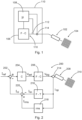
- FIG. 1 shows an electrosurgical generator 100 to which an electrosurgical instrument 102 is connected operating on a tissue 104, i.e. a working element, just schematically illustrated.
- the electrosurgical generator 100 comprises a frequency converter 106 which is controlled by a control device 108.
- the frequency converter 106 when in operation provides at its output 110 a voltage signal which is applied to the attached electrosurgical instrument 102, resulting in an operational current.
- a voltage sensor 112 for measuring the voltage signal and a current sensor 114 for measuring the operational current. These sensors 112, 114 are connected to the control device 108 for further consideration.
- the control device 108 calculates from the current sample values provided by the current sensor 114 a nonlinear current component. Based on that, the control device 108 controls the frequency converter 106. Accordingly, at the frequency converter output, the voltage signal is generated depending on the calculated nonlinear current component.
- the voltage sensor 112 might not be necessary as it is known what kind of voltage the voltage converter 106 generates. It is also possible that the voltage sensor 112 is connected to the frequency converter 106 directly. It is also possible that the control device 108 is part of the frequency converter 106.
- FIG 2 shows a schematic control structure 200.
- This control structure 200 illustrates that the control is based on a nonlinear current component I nl and a reference current I ref . These values are subtracted in the first summing element 202 resulting in a control error e.
- This control error e is passed to the control block 204 resulting in a set value for the voltage signal V set .
- This set value for the voltage signal V set is given to the frequency converter 206 which could be identical to the frequency converter 106 according to Figure 1 .
- the result of the frequency converter 206 is the voltage signal V sig .
- This voltage signal is passed to the electrosurgical instrument 208 which could be identical to the electrosurgical instrument 102 according to Figure 1 .
- the electrosurgical instrument 208 is also operating on a schematically illustrated tissue 210, i.e. on a working element.
- Applying the voltage signal V sig to the electrosurgical instrument 208 results in an operational current i OP .
- This operational current i OP is measured by means of a current sensor 214.
- This operational current i OP is thus the sampled current sampled by the current sensor 214.
- This sampled current is given to the Fourier transform block 216 and to the rms-block 218.
- the Fourier transform block 216 calculates first harmonic Fourier trigonometric coefficients and in this way identifies the linear current component I lin .
- the rms-block 218 calculates the root mean square value I rms and thus the effective value of the sampled current i OP .
- the nonlinear current component I nl is also an rms-value.
- this calculation of the nonlinear current component I nl is just a simplified illustration in Figure 2 not showing all calculation steps and preferably the current component I nl is calculated by taking the root of the difference of the square of the rms-value of the operating current I rms and the square of the linear current component I lin .
- the nonlinear current component I nl is calculated and provided to the first summing element 202 as explained above.
- the control block 204 can be designed such that depending on the error signal e, i.e. the result of the comparison of the reference value I ref and the nonlinear current component I nl , the voltage set value V set is either increased or decreased.
- the behavior might be similar to a PI-control. However, preferably, this can also be realized in a digital manner such that in each control cycle the voltage set value can be increased by a certain increment, if the error signal e is positive, or it can be decreased by a particular increment, which can be the same as for the explained increase, when the error signal is negative. Accordingly, this can be different to a I-behavior, as according to one aspect the amplitude of the error signal might not be taken into account, but only whether it is negative or positive. However, considering the particular value of the error signal might also be an option.
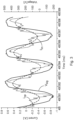
- Figure 3 shows recorded voltage and current data during TURis operation.
- the voltage is approximately sinusoidal while the current consists of a linear part and nonlinear part corresponding to plasma breakthroughs.
- the nonlinear current component can also be understood as “plasma current” and cannot be measured directly. The idea is therefore to separate the linear current component from the nonlinear current component, i.e. from the "plasma current' and control on the "plasma current” only.
- FIG. 3 The solid lines show measured voltage V sig and current i op data during TURis operation of an electrosurgical generator.
- the current is a combination of a capacitive current, which is 90° phase shifted with respect to the voltage, and current peaks which are in phase with the voltage. During ignition, there is a very high current in phase with the voltage.
- the dashed line shows the first harmonic component I lin of the sampled current i OP .
Landscapes
- Health & Medical Sciences (AREA)
- Surgery (AREA)
- Engineering & Computer Science (AREA)
- Life Sciences & Earth Sciences (AREA)
- Biomedical Technology (AREA)
- Molecular Biology (AREA)
- Nuclear Medicine, Radiotherapy & Molecular Imaging (AREA)
- Plasma & Fusion (AREA)
- Physics & Mathematics (AREA)
- Heart & Thoracic Surgery (AREA)
- Medical Informatics (AREA)
- Otolaryngology (AREA)
- Animal Behavior & Ethology (AREA)
- General Health & Medical Sciences (AREA)
- Public Health (AREA)
- Veterinary Medicine (AREA)
- Neurology (AREA)
- Neurosurgery (AREA)
- Surgical Instruments (AREA)
Applications Claiming Priority (1)
| Application Number | Priority Date | Filing Date | Title |
|---|---|---|---|
| US202363472838P | 2023-06-14 | 2023-06-14 |
Publications (1)
| Publication Number | Publication Date |
|---|---|
| EP4477169A1 true EP4477169A1 (fr) | 2024-12-18 |
Family
ID=91465472
Family Applications (1)
| Application Number | Title | Priority Date | Filing Date |
|---|---|---|---|
| EP24180700.7A Pending EP4477169A1 (fr) | 2023-06-14 | 2024-06-07 | Procédé de commande d'un instrument électrochirurgical capable de produire un plasma de coupe et générateur électrochirurgical correspondant |
Country Status (5)
| Country | Link |
|---|---|
| US (1) | US20240415561A1 (fr) |
| EP (1) | EP4477169A1 (fr) |
| JP (1) | JP2025003930A (fr) |
| CN (1) | CN119138996A (fr) |
| DE (1) | DE102023115741A1 (fr) |
Citations (7)
| Publication number | Priority date | Publication date | Assignee | Title |
|---|---|---|---|---|
| EP0219568A1 (fr) * | 1985-10-23 | 1987-04-29 | Erbe Elektromedizin GmbH. | Appareil électrochirurgical à haute fréquence |
| US4860745A (en) * | 1986-07-17 | 1989-08-29 | Erbe Elektromedizin Gmbh | High frequency electrosurgical apparatus for thermal coagulation of biologic tissues |
| US20030158546A1 (en) * | 1986-10-21 | 2003-08-21 | Gunter Farin | High frequency surgical instrument |
| US20080208185A1 (en) * | 2004-11-11 | 2008-08-28 | Erbe Elektromedizin Gmbh | Hf Surgical lnstrument |
| US20100198217A1 (en) * | 2007-07-19 | 2010-08-05 | Strauss Timo | High frequency surgery apparatus and method of operating same |
| US20160113702A1 (en) * | 2014-10-23 | 2016-04-28 | Erbe Elektromedizin Gmbh | Device for detecting metal when biological tissue is acted on by means of a sparking electrosurgical instrument |
| US20220395310A1 (en) * | 2021-06-11 | 2022-12-15 | Intuitive Surgical Operations, Inc. | Frequency based controlled electrosurgical system and method |
Family Cites Families (3)
| Publication number | Priority date | Publication date | Assignee | Title |
|---|---|---|---|---|
| DE3815835A1 (de) * | 1988-05-09 | 1989-11-23 | Flachenecker Gerhard | Hochfrequenzgenerator zum gewebeschneiden und koagulieren in der hochfrequenzchirurgie |
| PL2514380T3 (pl) * | 2011-04-21 | 2014-02-28 | Erbe Elektromedizin | Urządzenie elektrochirurgiczne umożliwiające lepsze cięcie |
| US20180368905A1 (en) * | 2015-11-30 | 2018-12-27 | Scott T. Latterell | Saline field electrosurgical system |
-
2023
- 2023-06-15 DE DE102023115741.8A patent/DE102023115741A1/de active Pending
-
2024
- 2024-05-07 JP JP2024075222A patent/JP2025003930A/ja active Pending
- 2024-06-07 EP EP24180700.7A patent/EP4477169A1/fr active Pending
- 2024-06-12 US US18/741,113 patent/US20240415561A1/en active Pending
- 2024-06-13 CN CN202410758655.9A patent/CN119138996A/zh active Pending
Patent Citations (7)
| Publication number | Priority date | Publication date | Assignee | Title |
|---|---|---|---|---|
| EP0219568A1 (fr) * | 1985-10-23 | 1987-04-29 | Erbe Elektromedizin GmbH. | Appareil électrochirurgical à haute fréquence |
| US4860745A (en) * | 1986-07-17 | 1989-08-29 | Erbe Elektromedizin Gmbh | High frequency electrosurgical apparatus for thermal coagulation of biologic tissues |
| US20030158546A1 (en) * | 1986-10-21 | 2003-08-21 | Gunter Farin | High frequency surgical instrument |
| US20080208185A1 (en) * | 2004-11-11 | 2008-08-28 | Erbe Elektromedizin Gmbh | Hf Surgical lnstrument |
| US20100198217A1 (en) * | 2007-07-19 | 2010-08-05 | Strauss Timo | High frequency surgery apparatus and method of operating same |
| US20160113702A1 (en) * | 2014-10-23 | 2016-04-28 | Erbe Elektromedizin Gmbh | Device for detecting metal when biological tissue is acted on by means of a sparking electrosurgical instrument |
| US20220395310A1 (en) * | 2021-06-11 | 2022-12-15 | Intuitive Surgical Operations, Inc. | Frequency based controlled electrosurgical system and method |
Also Published As
| Publication number | Publication date |
|---|---|
| CN119138996A (zh) | 2024-12-17 |
| DE102023115741A1 (de) | 2024-12-19 |
| JP2025003930A (ja) | 2025-01-14 |
| US20240415561A1 (en) | 2024-12-19 |
Similar Documents
| Publication | Publication Date | Title |
|---|---|---|
| US8920412B2 (en) | Electrosurgical generator for the treatment of a biological tissue, method for regulating an output voltage of an electrosurgical generator, and corresponding use of the electrosurgical generator | |
| EP2436326B1 (fr) | Contrôle ARC en temps réel dans des générateurs électro-chirurgicaux | |
| US20240293166A1 (en) | Control systems for electrosurgical generator | |
| EP2491882B1 (fr) | Appareil de chirurgie haute fréquence | |
| JP2671966B2 (ja) | 電気手術器用の処理装置及びその使用方法 | |
| JP5680013B2 (ja) | 切開を改良する電気外科装置 | |
| US5868739A (en) | System for cutting biological tissue | |
| US4114623A (en) | Cutting and coagulation apparatus for surgery | |
| US5108391A (en) | High-frequency generator for tissue cutting and for coagulating in high-frequency surgery | |
| CA2220904C (fr) | Systeme de commande pour unite electrochirurgicale de neurochirurgie | |
| CA2585622C (fr) | Systeme de commande adaptatif a base d'arc pour bloc chirurgical | |
| US9901386B2 (en) | Systems and methods for multifrequency cable compensation | |
| WO1996039086A1 (fr) | Regulation electrique d'un generateur electrochirurgical | |
| JPS62101239A (ja) | 高周波外科手術装置 | |
| US10166063B2 (en) | Device for detecting metal when biological tissue is acted on by means of a sparking electrosurgical instrument | |
| US20240415561A1 (en) | Method for controlling an electrosurgical instrument capable of producing a cutting plasma and corresponding electrosurgical generator | |
| KR20190130491A (ko) | 수성의 환경에서 플라즈마를 발생시키는 장치 및 방법 | |
| US20030158546A1 (en) | High frequency surgical instrument |
Legal Events
| Date | Code | Title | Description |
|---|---|---|---|
| PUAI | Public reference made under article 153(3) epc to a published international application that has entered the european phase |
Free format text: ORIGINAL CODE: 0009012 |
|
| STAA | Information on the status of an ep patent application or granted ep patent |
Free format text: STATUS: THE APPLICATION HAS BEEN PUBLISHED |
|
| AK | Designated contracting states |
Kind code of ref document: A1 Designated state(s): AL AT BE BG CH CY CZ DE DK EE ES FI FR GB GR HR HU IE IS IT LI LT LU LV MC ME MK MT NL NO PL PT RO RS SE SI SK SM TR |
|
| STAA | Information on the status of an ep patent application or granted ep patent |
Free format text: STATUS: REQUEST FOR EXAMINATION WAS MADE |
|
| 17P | Request for examination filed |
Effective date: 20250618 |