EP4477176A2 - Erfassungssystem und -verfahren - Google Patents
Erfassungssystem und -verfahren Download PDFInfo
- Publication number
- EP4477176A2 EP4477176A2 EP24190245.1A EP24190245A EP4477176A2 EP 4477176 A2 EP4477176 A2 EP 4477176A2 EP 24190245 A EP24190245 A EP 24190245A EP 4477176 A2 EP4477176 A2 EP 4477176A2
- Authority
- EP
- European Patent Office
- Prior art keywords
- tag
- coils
- field
- axis
- sensing system
- Prior art date
- Legal status (The legal status is an assumption and is not a legal conclusion. Google has not performed a legal analysis and makes no representation as to the accuracy of the status listed.)
- Pending
Links
Images


Classifications
-
- A—HUMAN NECESSITIES
- A61—MEDICAL OR VETERINARY SCIENCE; HYGIENE
- A61B—DIAGNOSIS; SURGERY; IDENTIFICATION
- A61B5/00—Measuring for diagnostic purposes; Identification of persons
- A61B5/05—Detecting, measuring or recording for diagnosis by means of electric currents or magnetic fields; Measuring using microwaves or radio waves
- A61B5/0515—Magnetic particle imaging
-
- A—HUMAN NECESSITIES
- A61—MEDICAL OR VETERINARY SCIENCE; HYGIENE
- A61B—DIAGNOSIS; SURGERY; IDENTIFICATION
- A61B1/00—Instruments for performing medical examinations of the interior of cavities or tubes of the body by visual or photographical inspection, e.g. endoscopes; Illuminating arrangements therefor
- A61B1/04—Instruments for performing medical examinations of the interior of cavities or tubes of the body by visual or photographical inspection, e.g. endoscopes; Illuminating arrangements therefor combined with photographic or television appliances
- A61B1/041—Capsule endoscopes for imaging
-
- A—HUMAN NECESSITIES
- A61—MEDICAL OR VETERINARY SCIENCE; HYGIENE
- A61B—DIAGNOSIS; SURGERY; IDENTIFICATION
- A61B5/00—Measuring for diagnostic purposes; Identification of persons
- A61B5/06—Devices, other than using radiation, for detecting or locating foreign bodies ; Determining position of diagnostic devices within or on the body of the patient
- A61B5/061—Determining position of a probe within the body employing means separate from the probe, e.g. sensing internal probe position employing impedance electrodes on the surface of the body
- A61B5/062—Determining position of a probe within the body employing means separate from the probe, e.g. sensing internal probe position employing impedance electrodes on the surface of the body using magnetic field
-
- G—PHYSICS
- G01—MEASURING; TESTING
- G01V—GEOPHYSICS; GRAVITATIONAL MEASUREMENTS; DETECTING MASSES OR OBJECTS; TAGS
- G01V15/00—Tags attached to, or associated with, an object, in order to enable detection of the object
-
- G—PHYSICS
- G01—MEASURING; TESTING
- G01V—GEOPHYSICS; GRAVITATIONAL MEASUREMENTS; DETECTING MASSES OR OBJECTS; TAGS
- G01V3/00—Electric or magnetic prospecting or detecting; Measuring magnetic field characteristics of the earth, e.g. declination, deviation
- G01V3/08—Electric or magnetic prospecting or detecting; Measuring magnetic field characteristics of the earth, e.g. declination, deviation operating with magnetic or electric fields produced or modified by objects or geological structures or by detecting devices
- G01V3/10—Electric or magnetic prospecting or detecting; Measuring magnetic field characteristics of the earth, e.g. declination, deviation operating with magnetic or electric fields produced or modified by objects or geological structures or by detecting devices using induction coils
-
- A—HUMAN NECESSITIES
- A61—MEDICAL OR VETERINARY SCIENCE; HYGIENE
- A61B—DIAGNOSIS; SURGERY; IDENTIFICATION
- A61B34/00—Computer-aided surgery; Manipulators or robots specially adapted for use in surgery
- A61B34/20—Surgical navigation systems; Devices for tracking or guiding surgical instruments, e.g. for frameless stereotaxis
- A61B2034/2046—Tracking techniques
- A61B2034/2051—Electromagnetic tracking systems
Definitions
- This invention relates to a sensing system and method for determining the location and orientation of an object which comprises a magnetic tag, for example within a body during medical and surgical procedures.
- objects which may be located or tracked include catheters, endoscopes and endoscopic capsules.
- the permanent magnet is located by an array of magnetic field sensors, external to the patient.
- the magnitude and angle of the magnetic field is used to infer the position of the permanent magnet.
- Such systems are limited by a requirement for a permanent magnet of several cubic millimetres in volume in order to produce a measurable signal, susceptibility to external magnetic fields (such as the earth's field), and inability to track multiple targets.
- external transmitter coils produce time-varying (AC) magnetic fields and an inductive pick-up coil (search coil) is located within the patient, in which a voltage is induced. Location is inferred by the (known) properties of the transmitted fields.
- Such systems also require an internal coil several cubic millimetres in volume, as well as requiring voltages (or data) to be retrieved from the search coil in order for real-time location to be possible.
- Operation frequency (and hence, signal strength) is limited by the need to avoid distortion in the transmitted fields, for example due to induced eddy current in tissue and other nearby conductive materials.
- the non-linear magnetic response of spherical magnetic particles has been used to produce odd harmonics of an AC field.
- this technique requires very large heavy interrogation coils and has a small sample volume, unsuitable for surgical applications. This may be why this technique seems never to have been proposed for the tracking of catheters and the like.
- a sensing system for determining the location and orientation of an object which comprises a magnetic tag, the sensing system comprising selection coils and interrogation coils, wherein:
- a method of locating an object within a human or animal body comprising the steps of: attaching a high aspect ratio ferromagnetic tag to the object to be located; determining the position of the ferromagnetic tag by locating the tag at a location in a spatially-varying DC magnetic field; and determining the orientation of the tag by sensing an AC response using coils which are sensitive to different vector directions for AC magnetic field.
- the invention therefore provides a system with accurate location and orientation yet which can employ a tag which is easily integrated into a medical component.
- a ferromagnetic ribbon or wire of material may be used having high magnetic permeability and preferably low coercivity, such as an amorphous or nanocrystalline alloy (e.g. Metglas 2826MB or the Vacuumschmeltze VITROVAC or VITROPERM materials) as the moveable item with the body (hereafter, the tag or label).
- an amorphous or nanocrystalline alloy e.g. Metglas 2826MB or the Vacuumschmeltze VITROVAC or VITROPERM materials
- This can be significantly smaller than the ⁇ 1 mm x 10 mm size typical of current systems.
- a highly extended aspect ratio is preferred to improve signal and orientation sensing performance, e.g.
- a 0.005 mm x 0.1 mm x 5 mm ribbon having an aspect ratio of 1000:1 between short and long edges is suggested as a possible size for this application.
- the high aspect ratio reduces the self-demagnetisation effect and so increases the effective magnetic permeability of the tag. This is in contrast to the low aspect ratio, nanometre-scale superparamagnetic particles used in MPI.
- a static or slowly varying "selection field" also called DC gradient field or bias field
- the tag becomes magnetically saturated quite easily and so has a non-linear response close to the zero of the selection field which is beneficial.
- the DC bias field is swept in order to locate the tag while the response to an AC "interrogation field" is monitored.
- the selection field typically takes the form of a “swept-DC” or “slowly varying” gradient field, with the variation being slow relative to the AC measurement frequency.
- a field-free point (FFP) or field-free line (FFL) can be generated and moved to search for the location of the tag.
- a simple coil configuration to achieve this is coil pairs in the x, y, and z axes, which are operated as Maxwell coils (currents in opposition) with varying current magnitudes between the coils to move the field-free point. Three or four Maxwell coil pairs are typically used to generate and rotate a field-free line within a plane.
- the tag orientation (or orientations) can be determined and tracked by iteratively adjusting the selection field to the track the peak of the AC response. This iterative approach has the advantage of being able to achieve a higher frame rate than performing a full scan for every frame.
- AC location systems are restricted to operation in the frequency ranges around tens of kilohertz in order to minimise distortion of the AC field by induced eddy currents and resulting loss of positional accuracy.
- a higher frequency AC interrogation field can be used without loss of positional accuracy.
- the use of a higher AC frequency is advantageous, as it provides a larger received voltage, a higher signal to noise ratio, and enables the use of lightweight, open sensing coils.
- the AC frequency is typically limited by the tag material and shape - typically somewhere in the range 10 4 to 10 6 Hz for amorphous or nanocrystalline tags.
- two or more AC interrogation frequencies (f 1 , f 2 , ...) are used.
- the non-linear magnetisation of the tag then produces intermodulation products of the AC interrogation frequencies at frequencies n*f 1 +m*f 2 , where n and m are positive or negative integers (e.g. 2*f 1 +f 2 , 2*f 2 +f 1 , 3*f 1 +2*f 2 , 3*f 2 +2*f 1 , etc.).
- This approach has the benefit that these frequencies can be measured with a very low noise floor, as they tend not to be produced accidentally by the AC sources.
- detection frequencies well-separated from the interrogation frequencies are used (i.e. 2*f 1 +f 2 rather than 2*f 1 -f 2 ) in order to allow sufficient bandwidth for interrogation frequencies to be filtered out by the detector circuit.
- a wide range of characteristic B-H curves and frequency responses may be designed by altering the chemical composition and post-processing of amorphous strips that would allow the system to distinguish between different strips and other ferromagnetic objects by measuring the characteristic spectra and their dependence on the field strength.
- the low coercivity and high permeability of the strips used as tags allows detection at moderately low field strengths and clear differentiation from magnetic steels which might be present in the region of the fields.
- AC fields are generated and detected by a plurality of AC coils.
- Other AC coils may be arranged specifically to produce orthogonal fields (i.e. field vectors which are at right angles to one another) within part of the sensed region. These two arrangements are referred to more generally as orthogonal coils, since many mutually orthogonal coil arrangements also produce approximately orthogonal fields throughout a reasonable volume. Transmit fields and receive angle sensitivities may be rotated by vector addition of signals on orthogonal coils.
- Orientation of the tags may be detected by:
- the line-width is defined here as the way the AC response changes in response to changing bias field - a smaller line-width is characteristic of a lower saturation field. Combinations of the techniques can be beneficial, for example to make it easier to measure all three rotation axes of an object.
- the gradient field is pulsed for lower average power input. This has the advantage of requiring less weight of copper for the coils, allowing a lower cost and more open coil arrangement.
- some or all of the coils are single-sided, to allow greater access to the patient.
- additional reference tags can be attached to the patient to allow imaging systems to compensate for patient movement when overlaying real-time tag positions on previously acquired x-ray CT or MRI data.
- a small (effectively static) selection field 105 is present in combination with the excitation field 106 (heavy dotted line).
- the magnetisation 107 also contains even harmonics (H2, H4 etc.).
- the quasi-static selection field 109 is significantly larger than H s and the excitation field superimposed upon it 108 does not take the tag out of the saturation regime. In this case, the tag magnetisation 110 remains constant and no signal is received from the tag.
- non-linear mixing products e.g.
- Figures 2-c show an example coil arrangement and associated selection fields.
- the selection fields advantageously produce a spatially varying magnetic field with a point or line with zero field, known in magnetic particle imaging as the field-free point (FFP) or field-free line (FFL).
- FFP field-free point
- FTL field-free line
- the simplest approach to this is a gradient field, which is most readily produced by a pair of Maxwell coils with opposing currents in the two coils. Varying the relative magnitudes of the currents moves the FFP.
- Figure 2a shows a set of gradient coils with x-axis 203, y-axis 204 and z-axis 202 pairs of coils.
- Figures 2b and 2c show simulations of selection fields produced by a pair of these coils (specifically, the x-axis coils, plotted in the y-x plane, but generalizable to any pair).
- the arrows show the in-plane magnetic field direction and the contours are of the magnitude of field strength in 10dB intervals.
- Figure 2b shows that when the current in the first coil 213 is equal and opposite to the current in the second coil 214, the FFP 211 is located in the centre of the system.
- Figure 2c shows the behaviour when the magnitude of the current in the second coil 214 is larger than that in the first coil 213.
- this position and orientation of this point and plane can be adjusted. Scanning of a surface that is field-free (at least in one vector) allows a faster search for tags than would be possible using a field-free point.
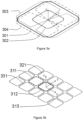
- Figure 3a shows a single-sided coil arrangement that can be employed.
- the coils include a large z-axis coil 301 and a smaller z-axis adjustment coil 302, an x-axis adjustment coil 303 (dotted line), and a y-axis adjustment coil 304 (dot-dash line).
- the two z-axis coils 301 and 302 have opposing currents, which create a FFP on the z-axis with z>0.
- the fields in this case are illustrated in Figure 4a (described in more detail later).
- the FFP moves in the +z direction (upwards).
- the fields in this case are illustrated in Figure 4b (described later).
- a current in the x-axis adjustment coil 303 shifts the FFP along the x-axis.
- the fields in this case are illustrated in Figure 4c (described later).
- a current in the y-axis adjustment coil 304 shifts the FFP along the y-axis.
- the FFP can be swept throughout the sensing volume to detect the location of the tag or tags.
- Interrogation (AC) signals can be superimposed on these coils or may be provided by a separate coil set. Similarly, received signals may be picked up on the selection coils, on the interrogation coil(s) or on separate dedicated receive coil(s).
- Figure 3b shows a single-sided coil arrangement.
- the selection coils take the form of a regular array, substantially filling the detection area. Individual control of currents to the coils in the array allow a FFP or FFL to be moved within the detection volume.
- a first 311 (dashed), second 312 (bold), and third 313 (dotted) coils are highlighted to illustrate the process of moving a FFP in the x-z plane.
- Relative currents in the three coils 311, 312 and 313 of 1, 0, and 3 respectively move the FFP in the -x direction, as illustrated in Figure 4c .
- field-free lines may be produced by driving rows of coils i.e. 311, 321, 331 with identical currents. This effectively reduces the field source a two dimensional one, and changes the FFP to a FFL.
- the use of a FFL can enhance scan rates for locating the tag(s).
- the earth's magnetic field can be of a similar magnitude to H s .
- magnetic field sensors such as GMR sensors, are located at the centre of each coil to assist with calibration and compensation for the earth's magnetic field.
- Interrogation and detection coils are advantageously separate large coils, each covering the entire detection volume (similar to 303, 304 and 301 in Figure 3a for the x, y, and z-axes respectively).
- Figure 3c shows an embodiment with permanent magnets providing the selection field, and an adjustment provided by electromagnets.
- a permanent magnet assembly 347 includes a central pole 346 and an annular pole 345 with opposing polarity to the central pole 346. Together these produce a FFP in on the z-axis above the x-y plane.
- a z-axis shift coil 341 (dashed line) moves the FFP in the z-direction.
- An x-axis shift coil 343 (dotted line) moves the FFP in the x-direction.
- a y-axis shift coil 344 (dot-dash line) moves the FFP in the y-direction.
- Figure 3d shows an embodiment of the invention with permanent magnets providing the selection field.
- a permanent magnet assembly 357 includes a central pole 356 and an annular pole 355 with opposing polarity to the central pole 356.
- Interrogation coils 353, 354 and 351 provide AC interrogation fields at the FFP in the x-, y- and z-axes respectively.
- the whole assembly is mechanically moved by a motorised stage 357 or manual operator in the case of a hand-held reader.
- Figures 4a-c show the movement of a field-free point or line from a single-sided coil arrangement according to the invention.
- a cross-section in the x-z plane is illustrated.
- the arrows show the in-plane field vector and the contours are of field strength at 10dB intervals.
- First 401a,b,c, second 402a,b,c, third 403a,b,c and fourth 404a,b,c conductors pass currents into and out of the page.
- a FFP or FFL 405a,b,c is located in the x-z plane, moveable throughout a sensing region. In the case of short conductors, being cross-sections of loops (as in Figure 3a ), a FFP is formed.
- a FFL is formed. This is similar to the case when rows of current loops are driven with the same current, e.g. in Figure 3b , coils 311, 321 and 331 would be driven with matching currents.
- the relative currents through the four conductors 401a, 402a, 403a, 404a are 1,-1,1,-1 respectively.
- the relative currents through the four conductors 401b, 402b, 403b, 404b are 1,-1.5,1.5,-1 respectively.
- the FFP or FFL 405b is moved in the +z direction.
- the relative currents through the four conductors 401c, 402c, 403c, 404c are 1,-1,3,-3 respectively.
- the FFP or FFL 405c is moved in the -x direction.
- Figures 5a-c illustrate a method of detecting the orientation of the tag.
- Figure 5a shows a tag 502, which is located at a FFP, or, as a minimal requirement, at a point where the selection field parallel to the long axis of the tag is less than H s .
- An AC interrogation field 501 is applied in the y' direction by a transmit coil.
- the tag 502 becomes magnetised along its easy magnetisation axis (i.e. the long axis), inducing a dipole moment m 503.
- the receiver is sensitive to fields in the x' direction, orthogonal to the interrogation field.
- *cos( ⁇ ) is directed along the x' axis.
- the receiver is able to pick up this component of induced dipole moment 504 and related harmonics and intermodulation products with minimal interference from the interrogation field 501.
- the interrogation transmit coil also has a shim coil associated with it, which performs a fine adjustment of the balancing of transmit and receive coils.
- This balancing (sometimes known as dynamic nulling in other inductive sensing applications) makes it possible to tune the orthogonality of the transmit and receive coils to beyond that achieved with standard manufacturing tolerances. It also allows for dynamic removal of extraneous transmit-to-receive breakthrough due to other conductive or magnetic objects in the vicinity of the coils.
- Figure 5b illustrates the magnitude of the received signal 511 as a function of the angle ⁇ between the tag and the receive sensitivity axis. The transmit and receive fields may be rotated to detect the tag angle in different planes.
- Figures 6a-c illustrate another method of detecting the orientation of the tag.
- Figure 6a shows a tag 602, typically located at a FFP to allow detection. Transmit coils produce interrogation fields on different axes.
- an interrogation field at frequency f 1 601 is produced on the y' axis
- an interrogation field at frequency f 2 603 is produced on the x' axis.
- an interrogation field at frequency f 3 would be transmitted on a z' axis, not in the plane of the diagram. However, this is omitted from the diagram for clarity.
- Figure 6b shows the received signals by this receiver coil as a function of tag rotation angle ⁇ .
- Harmonics of f 1 have a particular signature shown by the solid trace 611.
- Harmonics of f 2 have a particular signature shown by the dot-dash trace 612.
- Intermodulation products of f 1 and f 2 have a particular signature shown by the dotted trace 613. Extending to three dimensions, harmonics of f 3 , and intermodulation products of f 1 & f 3 , f 2 & f 3 , and of all three frequencies have their own signatures.
- Figure 6c illustrates an embodiment of the coil arrangement for the interrogation and detection coils.
- Selection coils are located in the region underneath the patient 621 (not shown).
- a large loop interrogation/detection coil is also located in this region 625.
- Interrogation/detection coils are located on either side of the patient.
- Dipole 622a&b, quadrupole 623a&b and octupole 624a&b coils are located on each side of the patient.
- Sets of dipole, quadrupole and octupole coils (e.g. 622a, 623a and 624a for the left side) are substantially orthogonal (balanced with respect to one another).
- interrogation signals at frequency f 1 are transmitted from a subset of the left coils 622a, 623a, 624a, interrogation signals at frequency f 2 from a subset of the right coils 622b, 623b, 624b, and interrogation signals at frequency f 3 from the z-axis interrogation coil 625.
- coil 623a might produce an x-axis field at f 1
- coil 624b might produce a y-axis field at f 2
- coil 625 would produce a z-axis field at f 3 .
- the remaining coils are then used to detect intermodulation products. Coil functions would then be swapped to make other measurements.
- Figures 7a-c illustrate another method of detecting the orientation of the tag.
- Figure 7a shows a ribbon-like tag 702 oriented with the long axis approximately parallel to the z-axis, the medium axis approximately parallel to the y-axis and the short axis approximately parallel to the x-axis.
- Figure 7b shows the magnitude of the harmonic (or intermodulation) response as the selection field is swept. As the selection field is swept in the z-axis, a sharp response is seen to the interrogation field 712, due to the easy magnetisation in this axis. As the selection field is swept in the y-axis, a broader response is seen 711.
- the harmonic response appears as the tag magnetisation becomes saturated 722.
- the harmonic response is seen at the lowest fields along the easy magnetisation axis.
- the harmonic response to an increasing excitation field amplitude along the y-axis is plotted 721 and emerges at a higher excitation field.
- the harmonic response vs. excitation field in the x-axis 720 would only be seen at the highest fields, if at all.
- This orientation angle dependence means that the relative responses in three sweep axes x', y', and z' can be used to estimate the orientation of the tag. For the case where the active region contains only tags with the same orientation, this can be performed without knowing the tag location. Alternatively, it can be performed in combination with a selection field to perform spatial selection.
- FIGs 8a-b illustrate tag arrangements in which the two ends of a tag can be distinguished from one another.
- Symmetrical tags might be oriented at 180 degrees to the intended direction, without the user being able to tell.
- the orientation of tapered tags can be detected due to by different responses of the thick end and the thin end, according to one of the previously described detection methods. For example, with the FFP on the thick end, response is larger than with the FFP located at the thin end of the tag.
- Figure 8a shows a tapered tag, which has the advantage of being simple to manufacture, being cut from a single piece of ribbon.
- Figure 8b shows an alternative tapered tag, which is more easily oriented in all three rotation axes.
- Figure 8c shows a tapered tag being constructed from multiple layers, producing a different tag thickness in different regions. In this instance, the value of H s is larger at the thick end of the tag.
- Figures 9a-b show flow charts for a tag tracking process.
- Figure 9a shows a flow chart for tracking the position of a single tag within the detection volume. Firstly the tag orientation is detected (for example, as described with regard to Figures 7a-c ), then the location is narrowed down by generating planes, lines and/or points where the field parallel to the tag orientation is zero. Finally, precise location can be tracked in real time as the tag moves by dithering location of a FFP and/or a detection angle to look for increases or decreases in tag response.
- Figure 9b shows a flow chart for tracking the position of a multiple tags within the detection volume. Firstly, a coarse positional sweep is performed, using a low field gradient, giving the approximate position of each tag.
- the orientation of each tag is measured.
- more precise measurements of position can then be made.
- position and orientation of the tags are iteratively tracked in real-time, as for the case with a single tag, but with interrogation being time-division multiplexed between the different tags.
- Figures 10a-d relate to an embodiment of the invention wherein an additional magneto-mechanical or magnetoelastic resonance is employed.
- Figure 10a shows a magnetoelastic tag 1001.
- the tag is excited into a longitudinal extensional vibration mode, as illustrated by the arrow 1002 and dotted lines.
- the resonant frequency of this vibration is affected by the length of the tag and the speed of longitudinal sound waves in the material, such that the tag length is half a wavelength (or a multiple thereof) at resonance.
- a typical speed of sound of around 4600m/s means that a 23mm long tag would resonate at around 100kHz in this mode.
- the tag would need to be flexibly mounted, so as not to damp the mechanical vibration.
- Figure 10b shows an exploded view of a magnetoelastic tag operating in bending mode.
- a magnetostrictive layer 1014 is bonded to a substrate 1013.
- the expansion and contraction of the magnetostrictive layer 1014 under an applied alternating field causes bending of a beam or cantilever 1017.
- the oscillating motion of the beam 1017 is illustrated by the double-ended arrow.
- the beam is mounted within a frame and within a cavity in this embodiment.
- the beam is provided with clearance by upper and lower spacers 1015 and 1012 respectively and sealed in by upper and lower caps 1016 and 1011 respectively.
- the lower layers 1011, 1012 and perhaps 1013) may be formed from a micromachined or etched silicon or glass wafer and the upper layers 1015 and 1016 may be formed from a second micromachined or etched silicon or glass wafer.
- the bending mode embodiment has the advantage that the resonant frequency is lower, so the tag can be made smaller. For example, a 3 mm long cantilever, 0.04 mm thick has a first resonant frequency at around 10kHz.
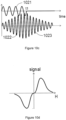
- Figure 10c shows a pulse-echo drive scheme, which allows detection of small signals from the tag during time periods when the large interrogation fields are switched off.
- the AC interrogation field 1021 is applied for a short time, t1.
- the magneto-acoustic resonant response of the tag 1022 and 1023 has a ring-up period 1022.
- the response of the tag continues to ring 1023, during a ring-down period, typically characterised by an exponential envelope the decay time of which is determined by the resonator quality factor.
- the response is shown at the second harmonic (H2), although the fundamental (H1) might be used in this embodiment. This has the advantage that the sensitive receiver circuits do not need to operate at the same time as the high power interrogation field, and do not become swamped by interfering signals.
- Figure 10d illustrates the tag response (y-axis, labelled “signal”) as a function of selection field (x-axis, labelled "H"), at a given AC interrogation field frequency.
- the frequency of the resonance is dependent on the Young's modulus of the material, which is itself dependent on the magnitude of the selection field for many magnetostrictive materials, including amorphous alloys.
- the degree of magnetostrictive coupling is also dependent on the magnitude of the selection field.
- the response to a swept selection field has a characteristic signature at a given frequency, typically including a response lobe at either side of the zero field.
- H2 even harmonic
- H4 fundamental frequency
- Figures 11a-b relate to an embodiment of the invention wherein an additional inductor-capacitor resonance is employed.
- Figure 11a illustrates a tag incorporating a wound inductor 1102 and separate capacitor 1103.
- the inductor is formed by winding wire 1102 around a saturable permeable core 1101.
- the selection field is high enough to saturate the magnetisation of the core 1101
- the ac permeability drops, and hence the inductance of the inductor drops
- the L-C resonant frequency f LC increases and the quality factor of the resonance drops.
- the selection field can be used to select for a response from the LC resonator, by looking for an AC response at the L-C resonant frequency for an unsaturated core (f LC0 ).
- Pulse-echo detection at the fundamental frequency (H1) or at an odd harmonic (H3, H5, etc.) of the AC interrogation field, is the preferred method of detecting this response, as illustrated in Figure 10c .
- FIG 11b illustrates a planar tag incorporating an L-C resonator.
- the tag includes a saturable permeable core 1111, a printed conductor 1112 wound around core.
- the conductor is a single foil on a substrate (not shown).
- the substrate is slotted and the core 1111 is woven through the substrate such that the conductor 1112 lies alternately above and below the core 1111.
- a planar capacitor is formed by adding a dielectric layer 1113 and a second electrode 1114 to form a parallel plate capacitor over part of the tag. This tag would operate in the same manner as the variant shown in Figure 11a .
- Figures 12a-b illustrate an example coil arrangement and associated selection fields. This embodiment is of particular benefit when the orientation of the tag 1207 is constrained so that the long axis lies along the z-axis, as shown. Only the selection field coils are shown: interrogation fields generation and tag detection could either be performed using the same coils or using additional coils and/or field sensors.
- the system includes a first x-axis selection coil 1201, in the form of a rectangular solenoid coil.
- the solenoid axis is along the z-axis and the current on the inner surface 1211 is in the +y direction.
- a second x-axis selection coil 1202 lies on the opposite side of the sensing region with its current 1212 in the same direction.
- a first y-axis sensing coil 1203 is also a rectangular solenoid with its axis along the z-axis.
- the current on the inner face of the first y-axis selection coil 1203 is in the +x direction, as shown by the arrow 1213.
- the second y-axis selection coil 1204 lies on the opposite side of the sensing volume and has it's current on the inner face 1214 in the same direction as the first y-axis selection coil.
- the z-axis selection coils 1205 and 1206, are conventional gradient coils (for example anti-Helmholtz coils) with currents 1215 and 1216 in opposite directions.
- Figure 12b illustrates the functioning of one pair of the solenoidal selection coils.
- a cross-section of the x-z plane is shown, with arrows indicating the component of the magnetic field along the z-axis (H z ).
- the contours show logarithmic contours of the magnitude of H z .
- the first x-axis selection coil 1221 has as currents flowing into and out of the page as shown by the cross and dot symbols respectively.
- the second x-axis selection coil 1222 lies on the opposite side of the sensing volume.
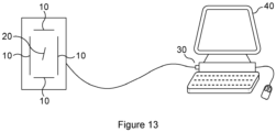
- Figure 13 shows the system of the present invention, with coils 10, tag 20 and processing and control means 30.
- the processing and control means 30 communicates with coils 10 to provide the necessary driving signals in accordance with the approaches described above and receives outputs from the relevant coils 10.
- the outputs are processed and means 30 provides an output to a display 40 indicating the location and orientation of the tag.
- the frequency of the fundamental frequency of the relevant magnetic field is assumed to be known a priori. From this the fundamental and several harmonic signals are synthesised for the same number of samples as were captured by the processing means 30. These are the reference signals.
- the reference signals are single sided - supported on the negative half of the frequency axis (i.e. of the form exp(-j* ⁇ *t) ). Being single sided means the phase is estimated as well as the amplitude so it is not necessary to know the phase of the reference signals, only the frequency (the amplitude of the orthogonal sine and cosine components are estimated independently - giving the phase).
- the inner product is taken of the captured data and each of the reference signals, giving the phase and amplitude of the the fundamental and the harmonics.
- This can be considered in several ways, it is the "Fourier transform" at each spot frequency (the harmonics and the fundamentals); Equivalently it is signal, downmixed to baseband, and then averaged over time (which is why longer acquisitions reduce the noise); Alternatively, since all the reference signals are approximately orthogonal, this is also equivalent to the least squares fit to the reference signal. Using these approaches the processing system can readily determine tag position and location.
- the present invention provides a system which can locate and determine the orientation of a tag in a simple and effective manner. It can operate with a tag which can be small and of a structure which enables it to be employed with medical devices that can be inserted easily into a body.
Landscapes
- Life Sciences & Earth Sciences (AREA)
- Health & Medical Sciences (AREA)
- Engineering & Computer Science (AREA)
- Physics & Mathematics (AREA)
- Surgery (AREA)
- Public Health (AREA)
- Medical Informatics (AREA)
- Veterinary Medicine (AREA)
- General Health & Medical Sciences (AREA)
- Animal Behavior & Ethology (AREA)
- Molecular Biology (AREA)
- Biophysics (AREA)
- Pathology (AREA)
- Biomedical Technology (AREA)
- Heart & Thoracic Surgery (AREA)
- Nuclear Medicine, Radiotherapy & Molecular Imaging (AREA)
- Geophysics (AREA)
- General Physics & Mathematics (AREA)
- General Life Sciences & Earth Sciences (AREA)
- Remote Sensing (AREA)
- Human Computer Interaction (AREA)
- Radiology & Medical Imaging (AREA)
- Electromagnetism (AREA)
- Geology (AREA)
- Environmental & Geological Engineering (AREA)
- Optics & Photonics (AREA)
- Geophysics And Detection Of Objects (AREA)
- Magnetic Resonance Imaging Apparatus (AREA)
- Radar Systems Or Details Thereof (AREA)
Applications Claiming Priority (3)
| Application Number | Priority Date | Filing Date | Title |
|---|---|---|---|
| GBGB1615847.9A GB201615847D0 (en) | 2016-09-16 | 2016-09-16 | Surgical tracking |
| PCT/GB2017/052760 WO2018051129A1 (en) | 2016-09-16 | 2017-09-18 | Sensing system and method |
| EP17781163.5A EP3512419B1 (de) | 2016-09-16 | 2017-09-18 | Abtastsystem und -verfahren |
Related Parent Applications (1)
| Application Number | Title | Priority Date | Filing Date |
|---|---|---|---|
| EP17781163.5A Division EP3512419B1 (de) | 2016-09-16 | 2017-09-18 | Abtastsystem und -verfahren |
Publications (2)
| Publication Number | Publication Date |
|---|---|
| EP4477176A2 true EP4477176A2 (de) | 2024-12-18 |
| EP4477176A3 EP4477176A3 (de) | 2025-03-26 |
Family
ID=57288722
Family Applications (2)
| Application Number | Title | Priority Date | Filing Date |
|---|---|---|---|
| EP24190245.1A Pending EP4477176A3 (de) | 2016-09-16 | 2017-09-18 | Erfassungssystem und -verfahren |
| EP17781163.5A Active EP3512419B1 (de) | 2016-09-16 | 2017-09-18 | Abtastsystem und -verfahren |
Family Applications After (1)
| Application Number | Title | Priority Date | Filing Date |
|---|---|---|---|
| EP17781163.5A Active EP3512419B1 (de) | 2016-09-16 | 2017-09-18 | Abtastsystem und -verfahren |
Country Status (4)
| Country | Link |
|---|---|
| US (2) | US12186069B2 (de) |
| EP (2) | EP4477176A3 (de) |
| GB (1) | GB201615847D0 (de) |
| WO (1) | WO2018051129A1 (de) |
Families Citing this family (6)
| Publication number | Priority date | Publication date | Assignee | Title |
|---|---|---|---|---|
| US10278779B1 (en) * | 2018-06-05 | 2019-05-07 | Elucent Medical, Inc. | Exciter assemblies |
| EP3583892A1 (de) * | 2018-06-20 | 2019-12-25 | Koninklijke Philips N.V. | Druckerfassungseinheit, system und verfahren zur ferndruckerfassung |
| US12521034B2 (en) | 2018-06-20 | 2026-01-13 | Koninklijke Philips N.V. | Tracking system and marker device to be tracked by the tracking system for a medical procedure |
| EP4008289A1 (de) * | 2020-12-03 | 2022-06-08 | Koninklijke Philips N.V. | Identifikationssystem zur identifikation eines medizinischen werkzeugs |
| US20250177700A1 (en) * | 2023-12-04 | 2025-06-05 | Freenav, Inc. | Device, system, and method for dual purpose tracking |
| CN118356177B (zh) * | 2024-06-17 | 2024-10-15 | 辽宁嘉玉科技有限公司 | 应用磁粒子成像的可控制激励强度的标记物距离探测设备 |
Citations (2)
| Publication number | Priority date | Publication date | Assignee | Title |
|---|---|---|---|---|
| GB2104099A (en) | 1981-08-13 | 1983-03-02 | Allied Corp | Amorphous antipilferage marker |
| US4704602A (en) | 1984-02-15 | 1987-11-03 | Intermodulation And Safety System Ab | Method and system for detecting an indicating device |
Family Cites Families (10)
| Publication number | Priority date | Publication date | Assignee | Title |
|---|---|---|---|---|
| US20010045826A1 (en) * | 2000-03-16 | 2001-11-29 | Schneider Mark R. | Distortion immune magnetic field generator for magnetic tracking systems and method of generating magnetic fields |
| US7158754B2 (en) * | 2003-07-01 | 2007-01-02 | Ge Medical Systems Global Technology Company, Llc | Electromagnetic tracking system and method using a single-coil transmitter |
| US7805269B2 (en) * | 2004-11-12 | 2010-09-28 | Philips Electronics Ltd | Device and method for ensuring the accuracy of a tracking device in a volume |
| JP2010512914A (ja) * | 2006-12-20 | 2010-04-30 | コーニンクレッカ フィリップス エレクトロニクス エヌ ヴィ | 作用領域の磁性粒子に影響を及ぼし、及び/又は該磁性粒子を検出する装置、並びにディスク形状のコイルの製造方法 |
| DE102007009210A1 (de) * | 2007-02-26 | 2008-08-28 | Siemens Ag | Bildgebendes tomographisches Verfahren und zugehörige Anordnung |
| BR112012019482A2 (pt) | 2010-02-08 | 2018-07-24 | Koninl Philips Electronics Nv | aparelho para influenciar e\ou detectar partículas magnéticas em um campo de visão, metodo para influenciar e/ou detectar partículas magneticas em um campo de visão e programa de computador |
| WO2014072854A1 (en) | 2012-11-07 | 2014-05-15 | Koninklijke Philips N.V. | Magnetic device for use in an mpi apparatus |
| US9360294B2 (en) * | 2013-10-31 | 2016-06-07 | Ascension Technology Corporation | Magnetic sensors |
| EP3139832A4 (de) * | 2014-05-07 | 2017-12-27 | The Trustees Of Dartmouth College | Verfahren und vorrichtung zur nichtlinearen suszeptibilitätsausmassbildgebung von magnetischen nanopartikeln |
| US9652038B2 (en) * | 2015-02-20 | 2017-05-16 | Sony Interactive Entertainment Inc. | Magnetic tracking of glove fingertips |
-
2016
- 2016-09-16 GB GBGB1615847.9A patent/GB201615847D0/en not_active Ceased
-
2017
- 2017-09-18 WO PCT/GB2017/052760 patent/WO2018051129A1/en not_active Ceased
- 2017-09-18 EP EP24190245.1A patent/EP4477176A3/de active Pending
- 2017-09-18 US US16/332,399 patent/US12186069B2/en active Active
- 2017-09-18 EP EP17781163.5A patent/EP3512419B1/de active Active
-
2024
- 2024-12-18 US US18/985,523 patent/US20250114011A1/en active Pending
Patent Citations (2)
| Publication number | Priority date | Publication date | Assignee | Title |
|---|---|---|---|---|
| GB2104099A (en) | 1981-08-13 | 1983-03-02 | Allied Corp | Amorphous antipilferage marker |
| US4704602A (en) | 1984-02-15 | 1987-11-03 | Intermodulation And Safety System Ab | Method and system for detecting an indicating device |
Also Published As
| Publication number | Publication date |
|---|---|
| US20200060578A1 (en) | 2020-02-27 |
| WO2018051129A1 (en) | 2018-03-22 |
| US12186069B2 (en) | 2025-01-07 |
| EP4477176A3 (de) | 2025-03-26 |
| GB201615847D0 (en) | 2016-11-02 |
| EP3512419A1 (de) | 2019-07-24 |
| EP3512419B1 (de) | 2024-07-24 |
| US20250114011A1 (en) | 2025-04-10 |
| EP3512419C0 (de) | 2024-07-24 |
Similar Documents
| Publication | Publication Date | Title |
|---|---|---|
| US20250114011A1 (en) | Sensing system and method | |
| Spetzler et al. | Exchange biased delta-E effect enables the detection of low frequency pT magnetic fields with simultaneous localization | |
| US7915891B2 (en) | MEMS device with tandem flux concentrators and method of modulating flux | |
| US6534982B1 (en) | Magnetic resonance scanner with electromagnetic position and orientation tracking device | |
| US7923999B2 (en) | MEMS device with supplemental flux concentrator | |
| US10539633B2 (en) | Ultrahigh resolution magnetic resonance imaging method and apparatus | |
| CN100522055C (zh) | 判定磁性粒子空间分布的方法 | |
| CN103460067B (zh) | 用于借助电磁传感器进行磁场测量的方法 | |
| JP5707495B2 (ja) | 磁気共鳴計測装置 | |
| KR20100058894A (ko) | Mri 해상도 향상을 위한 인체 밀착용 자기 공진기 및 그자기 공진기의 응용 장치 | |
| CN115184849B (zh) | 一种基于nmr探头的高分辨率磁场测量装置 | |
| JP2005131411A (ja) | コイル感度プロフィールを較正するためのシステム及び方法 | |
| Huong Giang et al. | Distance magnetic nanoparticle detection using a magnetoelectric sensor for clinical interventions | |
| Stupakov | Stabilization of Barkhausen noise readings by controlling a surface field waveform | |
| US7146282B1 (en) | Mechanical force detection of magnetic fields using heterodyne demodulation | |
| KR20150036941A (ko) | 하모닉 피크들의 패턴 분석을 이용한 물질 분석 방법 및 장치 | |
| WO2007004058A1 (en) | Local magnetic susceptometer unit | |
| JPS62207446A (ja) | 核磁気共鳴を用いた検査装置 | |
| Thalmayer et al. | A simple and low-cost technique to measure the magnetic susceptibility of ferrofluids | |
| Peshkovsky et al. | Noise-resilient multi-frequency surface sensor for nuclear quadrupole resonance | |
| JP2024025989A (ja) | 直流磁場測定方法および直流磁場測定装置、ならびに交流磁場測定方法および交流磁場測定装置 | |
| Xiang et al. | Magnetic induction sensing with a gradiometer coil and measurement circuit | |
| RU2829594C1 (ru) | Способ неразрушающего определения границ однородных намагничиваемых включений внутри объекта | |
| Huai‐ning | An investigation of microweighing with an eddy current transducer | |
| RU2118834C1 (ru) | Устройство для измерения слабых магнитных полей (варианты) |
Legal Events
| Date | Code | Title | Description |
|---|---|---|---|
| PUAI | Public reference made under article 153(3) epc to a published international application that has entered the european phase |
Free format text: ORIGINAL CODE: 0009012 |
|
| STAA | Information on the status of an ep patent application or granted ep patent |
Free format text: STATUS: REQUEST FOR EXAMINATION WAS MADE |
|
| 17P | Request for examination filed |
Effective date: 20240822 |
|
| AC | Divisional application: reference to earlier application |
Ref document number: 3512419 Country of ref document: EP Kind code of ref document: P |
|
| AK | Designated contracting states |
Kind code of ref document: A2 Designated state(s): AL AT BE BG CH CY CZ DE DK EE ES FI FR GB GR HR HU IE IS IT LI LT LU LV MC MK MT NL NO PL PT RO RS SE SI SK SM TR |
|
| REG | Reference to a national code |
Ref country code: DE Ref legal event code: R079 Free format text: PREVIOUS MAIN CLASS: A61B0034200000 Ipc: A61B0005050000 |
|
| PUAL | Search report despatched |
Free format text: ORIGINAL CODE: 0009013 |
|
| AK | Designated contracting states |
Kind code of ref document: A3 Designated state(s): AL AT BE BG CH CY CZ DE DK EE ES FI FR GB GR HR HU IE IS IT LI LT LU LV MC MK MT NL NO PL PT RO RS SE SI SK SM TR |
|
| RIC1 | Information provided on ipc code assigned before grant |
Ipc: A61B 34/20 20160101ALN20250220BHEP Ipc: A61B 5/06 20060101ALI20250220BHEP Ipc: A61B 5/05 20210101AFI20250220BHEP |
|
| STAA | Information on the status of an ep patent application or granted ep patent |
Free format text: STATUS: EXAMINATION IS IN PROGRESS |