EP4477196A2 - Dispositif et procédé de production de données de commande pour la correction opératoire d'un défaut de vision d'un oeil - Google Patents
Dispositif et procédé de production de données de commande pour la correction opératoire d'un défaut de vision d'un oeil Download PDFInfo
- Publication number
- EP4477196A2 EP4477196A2 EP24204715.7A EP24204715A EP4477196A2 EP 4477196 A2 EP4477196 A2 EP 4477196A2 EP 24204715 A EP24204715 A EP 24204715A EP 4477196 A2 EP4477196 A2 EP 4477196A2
- Authority
- EP
- European Patent Office
- Prior art keywords
- cornea
- cor
- correction
- volume
- refractive power
- Prior art date
- Legal status (The legal status is an assumption and is not a legal conclusion. Google has not performed a legal analysis and makes no representation as to the accuracy of the status listed.)
- Pending
Links
Images


Classifications
-
- A—HUMAN NECESSITIES
- A61—MEDICAL OR VETERINARY SCIENCE; HYGIENE
- A61F—FILTERS IMPLANTABLE INTO BLOOD VESSELS; PROSTHESES; DEVICES PROVIDING PATENCY TO, OR PREVENTING COLLAPSING OF, TUBULAR STRUCTURES OF THE BODY, e.g. STENTS; ORTHOPAEDIC, NURSING OR CONTRACEPTIVE DEVICES; FOMENTATION; TREATMENT OR PROTECTION OF EYES OR EARS; BANDAGES, DRESSINGS OR ABSORBENT PADS; FIRST-AID KITS
- A61F9/00—Methods or devices for treatment of the eyes; Devices for putting in contact-lenses; Devices to correct squinting; Apparatus to guide the blind; Protective devices for the eyes, carried on the body or in the hand
- A61F9/007—Methods or devices for eye surgery
- A61F9/008—Methods or devices for eye surgery using laser
- A61F9/00825—Methods or devices for eye surgery using laser for photodisruption
- A61F9/00827—Refractive correction, e.g. lenticle
-
- A—HUMAN NECESSITIES
- A61—MEDICAL OR VETERINARY SCIENCE; HYGIENE
- A61F—FILTERS IMPLANTABLE INTO BLOOD VESSELS; PROSTHESES; DEVICES PROVIDING PATENCY TO, OR PREVENTING COLLAPSING OF, TUBULAR STRUCTURES OF THE BODY, e.g. STENTS; ORTHOPAEDIC, NURSING OR CONTRACEPTIVE DEVICES; FOMENTATION; TREATMENT OR PROTECTION OF EYES OR EARS; BANDAGES, DRESSINGS OR ABSORBENT PADS; FIRST-AID KITS
- A61F9/00—Methods or devices for treatment of the eyes; Devices for putting in contact-lenses; Devices to correct squinting; Apparatus to guide the blind; Protective devices for the eyes, carried on the body or in the hand
- A61F9/007—Methods or devices for eye surgery
- A61F9/008—Methods or devices for eye surgery using laser
- A61F9/00825—Methods or devices for eye surgery using laser for photodisruption
- A61F9/00836—Flap cutting
-
- A—HUMAN NECESSITIES
- A61—MEDICAL OR VETERINARY SCIENCE; HYGIENE
- A61F—FILTERS IMPLANTABLE INTO BLOOD VESSELS; PROSTHESES; DEVICES PROVIDING PATENCY TO, OR PREVENTING COLLAPSING OF, TUBULAR STRUCTURES OF THE BODY, e.g. STENTS; ORTHOPAEDIC, NURSING OR CONTRACEPTIVE DEVICES; FOMENTATION; TREATMENT OR PROTECTION OF EYES OR EARS; BANDAGES, DRESSINGS OR ABSORBENT PADS; FIRST-AID KITS
- A61F9/00—Methods or devices for treatment of the eyes; Devices for putting in contact-lenses; Devices to correct squinting; Apparatus to guide the blind; Protective devices for the eyes, carried on the body or in the hand
- A61F9/007—Methods or devices for eye surgery
- A61F9/008—Methods or devices for eye surgery using laser
- A61F2009/00861—Methods or devices for eye surgery using laser adapted for treatment at a particular location
- A61F2009/00872—Cornea
-
- A—HUMAN NECESSITIES
- A61—MEDICAL OR VETERINARY SCIENCE; HYGIENE
- A61F—FILTERS IMPLANTABLE INTO BLOOD VESSELS; PROSTHESES; DEVICES PROVIDING PATENCY TO, OR PREVENTING COLLAPSING OF, TUBULAR STRUCTURES OF THE BODY, e.g. STENTS; ORTHOPAEDIC, NURSING OR CONTRACEPTIVE DEVICES; FOMENTATION; TREATMENT OR PROTECTION OF EYES OR EARS; BANDAGES, DRESSINGS OR ABSORBENT PADS; FIRST-AID KITS
- A61F9/00—Methods or devices for treatment of the eyes; Devices for putting in contact-lenses; Devices to correct squinting; Apparatus to guide the blind; Protective devices for the eyes, carried on the body or in the hand
- A61F9/007—Methods or devices for eye surgery
- A61F9/008—Methods or devices for eye surgery using laser
- A61F2009/00878—Planning
- A61F2009/0088—Planning based on wavefront
-
- A—HUMAN NECESSITIES
- A61—MEDICAL OR VETERINARY SCIENCE; HYGIENE
- A61F—FILTERS IMPLANTABLE INTO BLOOD VESSELS; PROSTHESES; DEVICES PROVIDING PATENCY TO, OR PREVENTING COLLAPSING OF, TUBULAR STRUCTURES OF THE BODY, e.g. STENTS; ORTHOPAEDIC, NURSING OR CONTRACEPTIVE DEVICES; FOMENTATION; TREATMENT OR PROTECTION OF EYES OR EARS; BANDAGES, DRESSINGS OR ABSORBENT PADS; FIRST-AID KITS
- A61F9/00—Methods or devices for treatment of the eyes; Devices for putting in contact-lenses; Devices to correct squinting; Apparatus to guide the blind; Protective devices for the eyes, carried on the body or in the hand
- A61F9/007—Methods or devices for eye surgery
- A61F9/008—Methods or devices for eye surgery using laser
- A61F2009/00878—Planning
- A61F2009/00882—Planning based on topography
-
- A—HUMAN NECESSITIES
- A61—MEDICAL OR VETERINARY SCIENCE; HYGIENE
- A61F—FILTERS IMPLANTABLE INTO BLOOD VESSELS; PROSTHESES; DEVICES PROVIDING PATENCY TO, OR PREVENTING COLLAPSING OF, TUBULAR STRUCTURES OF THE BODY, e.g. STENTS; ORTHOPAEDIC, NURSING OR CONTRACEPTIVE DEVICES; FOMENTATION; TREATMENT OR PROTECTION OF EYES OR EARS; BANDAGES, DRESSINGS OR ABSORBENT PADS; FIRST-AID KITS
- A61F9/00—Methods or devices for treatment of the eyes; Devices for putting in contact-lenses; Devices to correct squinting; Apparatus to guide the blind; Protective devices for the eyes, carried on the body or in the hand
- A61F9/007—Methods or devices for eye surgery
- A61F9/008—Methods or devices for eye surgery using laser
- A61F9/00825—Methods or devices for eye surgery using laser for photodisruption
- A61F9/00827—Refractive correction, e.g. lenticle
- A61F9/00829—Correction of higher orders
-
- A—HUMAN NECESSITIES
- A61—MEDICAL OR VETERINARY SCIENCE; HYGIENE
- A61F—FILTERS IMPLANTABLE INTO BLOOD VESSELS; PROSTHESES; DEVICES PROVIDING PATENCY TO, OR PREVENTING COLLAPSING OF, TUBULAR STRUCTURES OF THE BODY, e.g. STENTS; ORTHOPAEDIC, NURSING OR CONTRACEPTIVE DEVICES; FOMENTATION; TREATMENT OR PROTECTION OF EYES OR EARS; BANDAGES, DRESSINGS OR ABSORBENT PADS; FIRST-AID KITS
- A61F9/00—Methods or devices for treatment of the eyes; Devices for putting in contact-lenses; Devices to correct squinting; Apparatus to guide the blind; Protective devices for the eyes, carried on the body or in the hand
- A61F9/007—Methods or devices for eye surgery
- A61F9/008—Methods or devices for eye surgery using laser
- A61F9/00825—Methods or devices for eye surgery using laser for photodisruption
- A61F9/00838—Correction of presbyopia
Definitions
- the invention relates to a device for generating control data for controlling a laser device for the surgical correction of a patient's eye's ametropia, wherein the control data are designed to control a laser device which separates corneal tissue by irradiating laser radiation into the cornea of the eye, the device generates the control data in such a way that the laser device, when operated in accordance with the control data, emits the laser radiation in such a way that a volume in the cornea is isolated, the removal of which from the cornea brings about the desired ametropia correction, and the device for determining the control data calculates a radius of curvature which the cornea has after the volume has been reduced.
- the invention further relates to a method for generating control data for controlling a laser device for the surgical correction of a patient's eye's ametropia, wherein the control data are designed to control a laser device which separates corneal tissue by irradiating laser radiation into the cornea of the eye, the control data are created such that the laser device, when operated according to the control data, emits the laser radiation in such a way that a volume in the cornea is isolated, the removal of which from the cornea brings about the desired ametropia correction, and to determine the control data, a radius of curvature is calculated which the cornea has after the volume has been reduced.
- the invention in a second variant, relates to a method for generating control data which are designed to control a laser processing device for the surgical correction of ametropia in an eye, wherein a correction surface is specified which is to be generated in the cornea to remove a volume and which is not rotationally symmetrical with respect to the main direction of incidence, and wherein in the method the control data are generated on the basis of the correction surface such that the laser processing device generates the correction surface as a cutting surface in the cornea during operation, and the non-rotationally symmetric correction surface is adapted to a circular outline - seen in the main direction of incidence of the laser radiation.
- the invention further relates to a device for generating control data which are designed to control a laser processing device for the surgical correction of ametropia in an eye, wherein a correction surface is specified which is to be generated in the cornea as a cutting surface for removing a volume and which is non-rotationally symmetrical with respect to the main direction of incidence, and wherein the device generates the control data on the basis of the correction surface such that the laser processing device generates the correction surface in the cornea during operation, and the device adapts the non-rotationally symmetric correction surface to a circular outline - seen in the main direction of incidence of the laser radiation - when generating the control data.
- the classic way to correct vision problems in the human eye is with glasses.
- refractive surgery is now being used more and more, which corrects vision problems by changing the cornea.
- the aim of the surgical methods is to specifically change the cornea in order to influence the refraction of light.
- Various surgical methods are known for this.
- the most common is currently the so-called laser in situ keratomileusis, also abbreviated to LASIK.
- LASIK laser in situ keratomileusis
- a corneal lamella is first detached from the surface of the cornea on one side and folded to the side. This lamella can be detached using a mechanical microkeratome or a so-called laser keratome, such as that sold by Intralase Corp., Irvine, USA.
- the LASIK operation involves the use of an excimer laser, which ablates the exposed corneal tissue. After the volume in the cornea has been evaporated in this way, the corneal flap is folded back to its original position.
- the use of a laser keratome to expose the lamella is advantageous because it reduces the risk of infection and improves the quality of the cut.
- the lamella can be produced with a much more consistent thickness.
- the cut is also potentially smoother, which reduces later optical disturbances caused by this interface that remains after the operation.
- a series of optical breakthroughs are made at predetermined locations in such a way that the cut surface is formed. With the laser keratome, the cut surface forms the lamella that is to be folded down before the laser ablation is used.
- exposed corneal tissue is vaporized, which is also referred to as "grinding" the cornea using laser radiation.
- the volume removal required for correcting a vision defect is set for each surface element of the exposed cornea by the number of laser pulses and their energy.
- the LASIK method therefore provides a so-called shot file for the ablation laser, which is used for different points on the cornea, how often the laser beam should be directed at defined points on the cornea and with what energy.
- the volume removal was determined heuristically, not least because it depends very much on the ablation effect of the laser beam, and therefore on the wavelength, fluence, etc. of the radiation used.
- the condition of the cornea also plays a role; in particular, the moisture content of the cornea is important.
- the WO 96/11655 describes a device and a method for the LASIK method.
- a formula is given that calculates the corneal curvature radius to be achieved from the preoperative corneal curvature radius and the desired diopter correction.
- a similar calculation is available in the EP 1153584 A1 described - also for corneal ablation using LASIK.
- the US 5993438 proposes to remove a volume from the cornea by evaporation and absorption in the cornea.
- the WO 2005/092172 discloses how refractive power measurements obtained in one plane can be transformed to another plane.
- This approach can be used for various eye procedures, especially laser-assisted ablation.
- Another laser-based eye surgery procedure is to isolate the corneal volume to be removed rather than vaporizing it.
- the volume is therefore no longer ablated, but isolated in the cornea by a three-dimensional cutting surface and thus made removable.
- empirical values that were developed for grinding the cornea using ablation laser radiation are not useful. Instead, control data for operating the laser are required to isolate the corneal volume to be removed.
- US 6110166 and the US 7131968 B2 Such an eye surgical procedure is described. In US 6110166 different volume shapes are shown and it is mentioned that the specialist can select the appropriate volume.
- the DE 102006053118 A1 describes the generation of control data for volume-isolating refractive error correction.
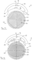
- a top view 33 of the lenticule surface 20 is shown. It determines the curvature that the front surface 15 of the cornea has after removal of the volume 18.
- Figure 11 shows a case where an astigmatic correction is to be made, which is why the lenticule surface 20 is an ellipsoid.
- two cutting lines 20.1 and 20.2 are shown for the cutting surface 20, which correspond to the main axes H1 and H2 of the ellipsoid surface.
- the volume 18 has a circular outline.
- the ellipsoid-shaped lenticule surface 20 is created by a spiral path 32, along which the position of the focus of the processing laser radiation is adjusted, i.e. on which the centers of the laser beam pulses are located, which cause the processing effect in the cornea 5.
- the processing laser radiation is darkened in areas of the spiral 32 that lie outside the circular outline, i.e. modified so that no processing effect occurs there.
- the connection between the lenticule surface 20 and the flap surface 19 can then be created by a simple circular cone-shaped lenticule edge surface 30.
- top view 33 of the lenticule surface 20 this is illustrated by a cross-hatched lenticule edge zone 31, which extends so deeply into the cornea that the total volume 18 is isolated by the flap surface 19, the lenticule surface 20 and the lenticule edge surface 30.
- the invention therefore relates to the concept of correcting the optical imaging errors of the human eye by using laser radiation to separate a volume of tissue in the cornea, which is then removed from the cornea. This results in a targeted change in the refractive power of the cornea. This change takes place locally, i.e. in the area of the cornea from which the volume of tissue is removed.
- the pupil of the eye is usually used as a guide.
- the removal of the separated volume changes the geometry, namely the curvature of the corneal surface.
- the volume to be separated and removed must therefore have special properties in terms of its shape.
- the separated volume is usually described by three interfaces.
- An anterior interface is placed at a constant distance under the cornea of the eye. This is particularly easy if the cornea is applanated with a flat contact lens. Since this cut surface is the most anterior in this direction, it is called the anterior surface or, in reference to the well-known LASIK procedure, the flap surface.
- the volume is also limited by a deeper cut surface, which is called the posterior cut surface or, since the volume can be understood as a lenticule, the lenticule surface. It is ensured that the total volume to be removed changes the curvature of the front surface of the cornea.
- anterior and posterior surfaces In principle, one could think of designing the anterior and posterior surfaces so that they have a common cutting line. On the one hand, this is not possible with a long-sightedness correction because the volume to be removed in the middle, i.e. in the area of the visual axis, has to be thinner than at the edge. On the other hand, for surgical reasons, one would also like to ensure a certain minimum thickness of the volume at the edge when correcting short-sightedness in order to be able to remove it easily.
- the anterior surface and the posterior surface are therefore connected via a so-called lenticule edge surface.
- the separated volume can be removed through these three cut surfaces, since the volume is then completely or almost completely enclosed by the cut surfaces.
- the absolute position and relative extent of the surfaces in the cornea determine the zone within which the optical effect occurs between these surfaces after the separated volume has been removed.
- the pupil is used as a guide here. This approach means that the two cut surfaces, namely the anterior and posterior cut surfaces, one or both of which can be optically effective, must be connected to form a closed volume that must have a suitable position within the cornea.
- the first variant of the invention is based on the object of developing a generic device or a generic method in such a way that control data for the surgical correction of refractive errors can be generated in the most computationally efficient way possible and at the same time more complex corrections can also be implemented.
- the invention therefore provides a control variable or a dimensioning variable on the basis of which the volume to be removed and thus the cut surface isolating this volume in the cornea can be calculated as precisely as possible. It defines an equation for the radius of curvature that the cornea should have after the removal of the volume isolated by the treatment device or the method. With this equation, the volume to be removed, and in particular the area effective for correction, can be calculated analytically precisely.
- the equation used in the first variant according to the invention for calculating the volume to be removed differs considerably on closer inspection from the approach used in the DE 102006053120 A1 was used.
- a different function is now used, which no longer takes into account the refractive power of glasses that are at a distance from the eye, but a refractive power distribution that varies at least radially when written in circular coordinates.
- this refractive power distribution which is used to calculate the new radius of curvature that the cornea should have after the surgical correction for the volume to be removed, is no longer at a distance from the cornea, but indicates the correction requirement in a plane that lies in the corneal vertex.
- the invention takes up the analytical approach of DE 102006053120 A1 and at the same time takes from the spectacle correction values used there Departure by introducing a radially varying refractive power distribution, which reflects the correction requirement in the plane lying in the corneal vertex.
- a correction value that corresponds to the previous correction value for glasses can now be applied in a central area around the optical axis, e.g. in the radius of the photopic pupil, and other refractive power values can be used for larger diameters.
- the volume or geometry of the corrective surface is now determined or can be determined via the equation in such a way that the cornea has the defined radius of curvature after removal of the volume.
- a particularly simple definition of volume that is easy to calculate and above all easy to implement (but by no means the only one) limits the volume without restriction to the first variant by a boundary surface that is divided into an anterior and a posterior partial surface (flap surface and lenticule surface), with the anterior partial surface being at a constant distance d F from the front surface of the cornea.
- the terms "anterior” and “posterior” correspond to the usual medical nomenclature.
- An additional edge surface may be necessary (for correction of farsightedness) or advantageous in order to connect the two partial surfaces and at the same time ensure a minimum edge thickness.
- the anterior partial surface (flap surface) is at a constant distance from the corneal surface, making it particularly easy to form this partial surface.
- the posterior partial surface (lenticule surface) is of course not necessarily at a constant distance from the anterior surface of the cornea.
- the optical correction is carried out by shaping the posterior partial surface (lenticule surface).
- This approach significantly simplifies the computational effort, since a spherical partial surface (the anterior partial surface) is particularly easy to calculate and the computational effort is concentrated on determining the posterior partial surface (lenticule surface).
- the posterior partial surface (lenticule surface) has a curvature that can be identical to the curvature of the anterior surface of the cornea after the volume has been removed, except for an additive constant.
- the distance that the anterior partial surface (flap surface) maintains from the anterior surface of the cornea is included in the constant.
- the radial dependence of the refractive power distribution present in the first variant according to the invention means that, viewed in polar coordinates, there are at least two radii for all angles at which different values of the refractive power distribution exist.
- the refractive power distribution used can be the result of a calculation using wavefront measurement or topography measurement of the front surface of the cornea. Accordingly, the equation according to the invention, from which the calculation of the corneal volume is based, also provides a local radius of curvature of the cornea.
- the coordinate system selected here is preferably related to the corneal vertex.
- ⁇ z(r, ⁇ ) is always positive. However, this is not a necessary condition for the correction. It is also possible to change the refractive correction and the associated change in the curvature of the front of the cornea by introducing an additional volume into the cornea. In this case, ⁇ z(r, ⁇ ) is always negative. Mixed cases are also possible in which ⁇ z(r, ⁇ ) has both positive and negative components. In practice, this is the case when, for example, a small refractive correction for distance vision in the case of myopia is achieved by extracting tissue and at the same time a Correction of presbyopia is to be carried out by implanting a small lens in the central area of the optical zone. In this case, the thickness of the implant can be greater than the thickness of the volume of tissue to be removed for myopia correction and thus ⁇ z(r, ⁇ ) can have positive values in the central area and negative values in the peripheral area.
- the thickness profile ⁇ z(r, ⁇ ) of the volume results from the difference of the topographies. If the desired topography is known after the correction z CV '(r, ⁇ ), the thickness profile is also determined.
- the expert can now determine z CV *(r, ⁇ ) from R CV *(r, ⁇ ) analytically or using suitable numerical methods by integrating twice over the area.
- the two integration constants that arise are chosen so that, for example, the desired treatment diameter for the refractive correction is created and at the same time the volume to be removed is minimized.
- the refractive power distribution used for correction can have different values in certain pupil areas, e.g. a central area and a peripheral area, in order to achieve an optical correction that achieves optimal results even under widely varying viewing conditions or is optimally adapted to the individual, e.g. in the case of presbyopia.
- a special case of separation occurs when the refractive power distribution has no angle dependence. Since this is particularly simple computationally, it is preferred that the local refractive power change is determined to be angle-independent when determining the control data.
- the refractive power can also be used in a completely analogous manner, so that all explanations given here in connection with the radius of the anterior surface of the cornea naturally also apply analogously to the refractive power representation or view if R is replaced by B in accordance with the above-mentioned context.
- the invention is based on the task of defining the closed volume within the cornea in such a way that it is as convenient for application as possible and, in particular, to allow the connection of the two optically effective boundary surfaces, namely the anterior and the posterior surface (flap and lenticule surface), in such a way that secondary biophysical and/or medical effects can influence the intended optical Do not adversely affect the corrective effect, whereby at least one of the surfaces is not rotationally symmetrical.
- control data which are designed to control a laser processing device for the surgical correction of ametropia in an eye, wherein a correction surface is specified which is to be generated in the cornea to remove a volume and which is non-rotationally symmetrical with respect to the main direction of incidence, and wherein in the method the control data are generated on the basis of the correction surface in such a way that the laser processing device generates the correction surface in the cornea during operation and the non-rotationally symmetrical correction surface is adapted to a circular outline - seen in the main direction of incidence of the laser radiation, wherein a transition region is provided for the correction surface in which it is adapted from the non-rotationally symmetrical shape to an edge which is rotationally symmetrical with respect to the main direction of incidence, wherein the rotationally symmetrical edge is circular and lies in a plane which is perpendicular to the main direction of incidence and which, with respect to the main direction of incidence, is neither more anterior than the most anterior
- a device for generating control data which are designed to control a laser processing device for the surgical correction of ametropia in an eye, wherein a cutting surface is specified which is to be generated in the cornea to remove a volume and which is non-rotationally symmetrical with respect to the main direction of incidence, and wherein the device generates the control data on the basis of the correction surface in such a way that the laser processing device generates the correction surface in the cornea during operation, and the device, when generating the control data, adapts the non-rotationally symmetrical correction surface to a circular outline - seen in the main direction of incidence of the laser radiation, wherein the device, when generating the control data for the cutting surface, provides a transition region in which the correction surface is adapted from the non-rotationally symmetrical shape to an edge which is rotationally symmetrical with respect to the main direction of incidence, wherein the rotationally symmetrical edge is circular and lies in a plane which is perpendicular to the main direction of
- the volume is limited by an anterior surface, which is referred to as the flap surface or anterior surface in reference to the well-known LASIK procedure.
- the volume is limited by a posterior surface or lenticule surface. At least one of these surfaces affects the postoperative curvature of the front of the cornea, i.e. the curvature of the front of the cornea after the volume has been removed.
- this corrective surface is the lenticule surface. However, this should not be understood as a restriction.
- the corrective area of the relevant surface(s) is referred to as the correction zone.
- this correction zone is not rotationally symmetrical, since higher aberrations, e.g. astigmatism, are also to be corrected.
- the correction zone is only part of the corrective surface (e.g. the lenticule surface).
- a correction surface is specified for the correction zone when calculating the correction requirement or before calculating the control data. If there is only one corrective surface, the surface geometry of the correction surface is crucial for the surface geometry of the cornea after surgery.
- the correction surface is not rotationally symmetrical, it usually has a non-rotationally symmetrical edge. This edge is followed by a transition zone in the surface, which continues the non-rotationally symmetrical edge of the correction surface so that the entire cutting surface has a rotationally symmetrical edge.
- the cutting surface relevant to correction e.g. the lenticule surface
- the flap surface and the lenticule surface do not yet define a closed volume.
- the lenticule edge surface which connects the rotationally symmetrical edges of the flap surface and the lenticule surface, is still missing. Since two rotationally symmetrical edges are connected in this way, the lenticule edge surface can be designed as a circular cylinder surface or a circular conical surface.
- a correction surface is specified for the correction, which, as already mentioned, is not rotationally symmetrical when correcting higher aberrations.
- the adaptation to a rotationally symmetrical edge can be achieved by adding the transition zone to the correction surface. It is also possible to modify an edge area of the correction surface, which is usually done by only implementing a certain central part of the actually specified correction surface in the cutting surface and then connecting the transition zone to this part of the correction surface. Which of the two options is chosen depends solely on how far the specified correction area covers the desired pupil area. If it is sufficiently larger than the desired pupil area in which the optical correction is to take effect, the second option (modifying the edge area of the correction area) can be selected. In the other case, the transition zone will be added to the correction area. From the point of view of the principles described here, however, there is no substantial difference between these two options.
- the invention of the second variant therefore provides for a transition region (here also referred to as transition zone) which continuously adjoins the radial boundary of the non-rotationally symmetrical surface and continues this onto a rotationally symmetrical edge which, with respect to the main axis of incidence, is not higher or lower than the actual correction surface itself.
- transition zone a transition region which continuously adjoins the radial boundary of the non-rotationally symmetrical surface and continues this onto a rotationally symmetrical edge which, with respect to the main axis of incidence, is not higher or lower than the actual correction surface itself.
- the refractive correction is created by the geometry of the anterior cut surface F A (flap surface) and the posterior cut surface F R (lenticule surface) of the tissue volume to be extracted.
- the shape of both surfaces F A , F P is determined by the local refractive power correction B(r, ⁇ ) (see e.g. DE 102006053120 A1 ).
- the radial (lateral) dimensions r MAX (F A , ⁇ ) and r MAX (F P , ⁇ ) of these two surfaces are at least as large as the radius of the correction zone in which the refractive power correction is to take place.
- the correction zone usually covers the optical zone of the cornea, i.e. the zone through which light rays penetrate, which then contribute to the imaging on the retina.
- the smallest distance between the two surfaces F A and F P along these edge curves r MAX (F A , ⁇ ) and r MAX (F P , ⁇ ) is generally not constant (see also DE 102007053281 A1
- Continuous transition regions ÜZ A and ÜZ P are attached to the edge curves of the respective non-rotationally symmetric boundary surface r MAX (F A , ⁇ ) and/or r MAX (F P , ⁇ ), which then transition to a circular edge.
- a transition region can also be attached to only one of the two surfaces.
- the transition area can in principle be used for any type of cutting surface generation. As will be explained below, it is particularly useful to generate cutting surfaces by arranging laser radiation pulses that are introduced into the cornea along a predetermined path. However, this is not mandatory; other types of cutting surface generation are also possible. Under the additional condition of technically strictly limited speed and acceleration of the z-focus adjustment of the laser radiation, the method of the so-called contour line scan according to WO 002005011547 A1 suitable for producing any curved cutting surfaces by arranging laser shots along a path.
- the transition zone supplements the correction surface or adapts it so that it has a rotationally symmetrical edge. This can be done particularly easily by designing the transition area as a flat surface that is perpendicular to the main direction of incidence, adjoins the edge of the correction surface, which is guided to the plane in which the flat surface lies, and which supplements the correction surface to the circular outline. If the non-rotationally symmetrical edge of the correction surface is not yet in one plane, in this variant the cutting surface is supplemented until the non-rotational edge of the correction surface is in one plane.
- the laser processing device is designed to focus processing laser radiation into the cornea of the eye along a main direction of incidence and to adjust the position of the laser focus in the cornea, and the rotationally symmetrical edge is determined, the control data are generated in such a way that they specify a path along which the laser focus is to be adjusted, wherein the path lies in the specified correction area and spirals from an interior of the specified Correction surface runs to its edge, wherein the control data in the transition region continue the spiral in such a way that it reduces the distance between the edge of the predetermined correction surface and the rotationally symmetrical edge per revolution according to a predetermined function, preferably linearly.
- the rotating spiral reduces the distance between the edge of the specified correction surface and the rotationally symmetrical (circular) edge per revolution according to a predetermined function. In areas where the distance between the non-rotationally symmetrical edge of the correction surface and the circular edge is small, the paths become narrower; in areas where the distance is comparatively larger, the paths become further apart.
- the minimum and maximum distance between successive spiral turns can be set particularly easily by the number of revolutions and the choice of function.
- the laser processing device is designed to focus processing laser radiation into the cornea of the eye along a main direction of incidence and to adjust the position of the laser focus in the cornea, and the control data are generated in such a way that they specify a path along which the laser focus is to be adjusted, wherein the path lies in the predetermined correction surface and runs spirally from an interior of the predetermined correction surface to its edge, wherein in the transition region the path is designed as a spiral or concentric circles lying in the flat surface, and for those sections of the spiral or concentric circles lying in the flat surface which would overlap with the correction surface when viewed along the main direction of incidence, the control data provide for deactivation of the laser radiation with regard to its processing effect.
- the processing laser beam is therefore darkened in those areas in which the spiral or the circles that make up the flat surface would overlap with the correction surface, i.e. it is set so that no processing effect occurs there.
- This can be done by controlling a suitable modulator or attenuator that is located in the beam path, or by appropriately controlling the laser radiation source itself.
- suitable means for this from the state of the art, for example from the US 2008/0021443 A1 , the disclosure of which is incorporated herein in its entirety.
- the methods according to the invention of all variants for generating the control data can be carried out without recourse to human intervention.
- they can be carried out by a computer which, under the control of a program according to the invention, carries out the method according to the invention and, from corresponding specifications, generates the control data for the laser device determines.
- the involvement of a doctor is not required in any way when determining the control data, since determining the control data does not involve any therapeutic intervention. This only takes place when the previously determined control data is applied.
- Figure 1 shows a treatment device 1 for an eye surgical procedure, which corresponds to the EP 1159986 A1 or the US 5549632 described.
- the treatment device 1 uses a treatment laser radiation 2 to correct a vision defect in an eye 3 of a patient 4.
- the vision defect can include hyperopia, myopia, presbyopia, astigmatism, mixed astigmatism (astigmatism in which there is hyperopia in one direction and myopia in a direction perpendicular to it), aspherical errors and higher-order aberrations.
- the treatment laser radiation 2 is applied in the described embodiment as a pulsed laser beam focused on the eye 3.
- the pulse duration is in the femtosecond range, for example, and the laser radiation 2 acts in the cornea by means of non-linear optical effects.
- the laser beam has, for example, 50 to 800 fs short laser pulses (preferably 100 - 400 fs) with a pulse repetition frequency of between 10 and 500 kHz.
- the components of the device 1 are controlled by an integrated control unit, which can of course also be designed independently.
- the refractive error of eye 3 is measured using one or more measuring devices.
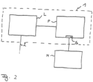
- FIG. 2 shows the treatment device 1 schematically.
- a laser device L emits the laser beam 2 onto the eye 3.
- the operation of the laser device L is fully automatic, ie the laser device L starts the deflection of the laser beam 2 upon a corresponding start signal and thereby creates cutting surfaces that are constructed in a manner to be described and have a volume in the cornea of the eye.
- the laser device L receives the control data required for operation from a planning device P in advance as a control data set via unspecified control lines. The transmission takes place before the laser device L is operated.
- communication can also be wireless.
- control data set is transmitted to the treatment device 1 and further preferably, operation of the laser device L is blocked until a valid control data set is available at the laser device L.
- a valid control data set can be a control data set that is in principle suitable for use with the laser device L of the treatment device 1.
- the validity can also be linked to the passing of further tests, for example whether additional information about the treatment device 1, e.g. a device serial number, or the patient, e.g. a patient identification number, stored in the control data set matches other information that was read out on the treatment device or entered separately, for example, as soon as the patient is in the correct position for operation of the laser device L.
- the planning unit P generates the control data set, which is made available to the laser unit L for carrying out the operation, from measurement data and refractive error data that were determined for the eye to be treated. They are fed to the planning unit P via an interface S and, in the embodiment shown, come from a measuring device M that has previously measured the eye of the patient 4. Of course, the measuring device M can transmit the corresponding measurement and refractive error data to the planning device P in any manner.
- the transfer can be carried out using memory chips (e.g. via USB or memory stick), magnetic storage (e.g. floppy disks), wirelessly (e.g. WLAN, UMTS, Bluetooth) or wired (e.g. USB, Firewire, RS232, CAN bus, Ethernet, etc.).
- memory chips e.g. via USB or memory stick
- magnetic storage e.g. floppy disks
- wirelessly e.g. WLAN, UMTS, Bluetooth
- wired e.g. USB, Firewire, RS232, CAN bus, Ethernet, etc.
- a direct radio or wire connection between the measuring device M and the treatment device 1 with regard to data transmission which can be used in one variant, has the advantage that the use of incorrect measurement and refractive error data is excluded with the greatest possible certainty.
- the measurement and refractive error data can also be transmitted to the treatment device 1 at the same time.
- the planning device P always generates the control data record belonging to the patient 4, and an erroneous use of an incorrect control data record for a patient 4 is virtually excluded.
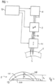
- the mode of action of the laser beam 2 is Figure 3 indicated schematically.
- the treatment laser beam 2 is focused into the cornea 5 of the eye 6 by means of an unspecified optic. This creates a focus in the cornea 5 that covers a spot 6 and in which the laser radiation energy density is so high that, in combination with the pulse length, a non-linear effect occurs in the eye.
- each pulse of the pulsed laser radiation 2 can generate an optical breakthrough in the cornea 5 at the respective spot 6, which in turn creates a Figure 3 schematically indicated plasma bubble is initiated.
- This laser pulse separates tissue in the cornea 5. When a plasma bubble is formed, the tissue layer separation covers a larger area than the spot 6 covered by the focus of the laser radiation 2, although the conditions for generating the breakthrough are only achieved in the focus.
- the energy density ie the fluence of the laser radiation
- the energy density must be above a certain pulse length-dependent threshold value. This connection is known to the expert, for example, from the DE 69500997 T2 known.
- a tissue-separating effect can also be generated by the pulsed laser radiation by emitting several laser radiation pulses in one area, with the spots 6 overlapping for several laser radiation pulses. Several laser radiation pulses then work together to achieve a tissue-separating effect.
- tissue separation used by the treatment device 1 is not relevant for the following description, even if this description describes pulsed treatment laser radiation 2.
- a treatment device 1 can be used as described in the WO 2004/032810 A2
- a large number of laser pulse foci form a cutting surface in the tissue, the shape of which depends on the pattern with which the laser pulse foci are arranged in the tissue.
- the pattern specifies target points for the focus position at which one or more laser pulses are emitted, and defines the shape and position of the cutting surface.
- material is removed from an area within the cornea 5 using pulsed laser radiation by separating tissue layers that isolate the material and then allow the material to be removed.
- the removal of the material causes a change in volume in the cornea, which results in a change in the optical imaging effect of the cornea 5, which is precisely dimensioned so that the previously determined vision defect is/will be corrected as far as possible.
- the focus of the laser radiation 2 is directed at target points in the cornea 5, usually in an area that lies below the epithelium and Bowman's membrane and above Decemet's membrane and the endothelium.
- the treatment device 1 has a mechanism for adjusting the position of the focus of the laser radiation 2 in the cornea 5. This is shown schematically in Figure 3 shown.
- the laser radiation 2 is, as already mentioned, bundled in a focus 7 in the cornea 5, and the position of the focus 7 in the cornea is adjusted so that energy from laser radiation pulses is introduced into the tissue of the cornea 3 in a focused manner at different points to create the cutting surface.
- the laser radiation 2 is provided by a laser 8 as pulsed radiation.
- the xy scanner 9 thus causes an adjustment of the position of the focus 7 essentially perpendicular to the main direction of incidence of the laser radiation 2 into the cornea 5.
- a z scanner 11 is provided for adjusting the depth, which is designed, for example, as an adjustable telescope.
- the z scanner 11 ensures that the z position of the position of the focus 7, i.e. its position on the optical axis of incidence, is changed.
- the z scanner 11 can be arranged upstream or downstream of the xy scanner 9.
- the coordinates designated below as x, y, z therefore refer to the deflection of the position of the focus 7.
- z always denotes the coordinate along the optical axis of incidence of the laser radiation 2
- x and y denote two mutually orthogonal coordinates in a plane perpendicular to the direction of incidence of the laser beam.
- the person skilled in the art is of course aware that a three-dimensional description of the position of the focus 7 in the cornea 5 can also be made using other coordinate systems, in particular it does not have to be a rectangular coordinate system. It is therefore not essential that the xy scanner 9 deflects around axes that are at right angles to each other, rather any scanner can be used. which is able to adjust the focus 7 in a plane in which the axis of incidence of the optical radiation does not lie. This also makes oblique coordinate systems possible.
- non-Cartesian coordinate systems can also be used to describe or control the position of the focus 7, as will be explained below.
- Examples of such coordinate systems are spherical coordinates (also called spherical coordinates) and cylindrical coordinates.
- the xy scanner 9 and the z scanner 11 which together implement a concrete example of a three-dimensional focus adjustment device, are controlled by a control unit 12 via unspecified lines.
- the control unit 3 ensures a suitably synchronous operation of the laser 8 and the three-dimensional focus adjustment device, implemented by way of example by the xy scanner 9 and the z scanner 11, so that the position of the focus 7 in the cornea 5 is adjusted in such a way that ultimately a material of a certain volume is isolated, with the subsequent volume removal bringing about a desired correction of the visual impairment.
- the control device 12 works according to predetermined control data, which specify the target points for the focus adjustment.
- the control data is usually summarized in a control data set. In one embodiment, this specifies the coordinates of the target points as a pattern, whereby the order of the target points in the control data set determines the sequence of the focus positions and thus ultimately a trajectory (also referred to here for short as path).
- the control data set contains the target points as concrete control values for the focus position adjustment mechanism, e.g. for the xy scanner 9 and the z scanner 11.
- the target points and preferably also their order in the pattern are determined. The surgical procedure must be planned in advance so that the control data for the treatment device 1 is determined, the application of which then achieves an optimal visual impairment correction for the patient 4.
- the volume to be isolated from the cornea 5 and later removed must be determined. As already shown in Figure 2 As described above, this requires an assessment of the need for correction.
- the addition of an asterisk to sizes indicates that these are sizes obtained after correction.
- the radius of curvature Rcv of the front of the cornea 15 is modified by the volume removal.
- the cornea 5 reduced by the volume with the modified corneal surface 15* has a correspondingly modified imaging effect due to the modified front curvature, so that a corrected focus is on the retina 14.
- the curvature R*cv of the modified anterior corneal surface 15* to be achieved is therefore determined.
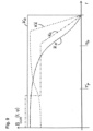
- n c denotes the refractive power of the corneal material. The corresponding value is usually 1.376; B COR denotes a change in refractive power that is necessary to correct refractive errors. B COR is radially dependent. Radial dependence means that there are two values r1 and r2 for the radius r, for which the change in refractive power has different values at all angles ⁇ .
- Figure 9 shows the function B COR in various example curves Ka to Ke as a function of the radius r.
- Ka is the conventional refractive index of a state-of-the-art pair of glasses according to DE 102006053120 A1 , in the representation of the Figure 9 however, already related to the level of the corneal vertex.
- the curve Kb is constant up to a radius that lies beyond a radius r s and then drops off.
- the radius r s is the scotopic pupil radius, i.e. the pupil radius that occurs when seeing in the dark.
- the change in refractive power according to curve Kc is piecewise constant up to the value r s , with a jump from a higher value to a lower value below a radius r p , which corresponds to the photopic pupil radius.
- Such a variation in the refractive power correction across the pupil cross-section is particularly advantageous in the case of presbyopia.
- close-up vision usually occurs in good lighting, e.g. when reading. Due to the good lighting, the pupil is then usually constricted to the photopic pupil radius.
- the refractive power correction value then required provides optimal adaptation to near vision, e.g. an optimal viewing distance of around 25 to 70 cm.
- dark vision which is usually associated with distance vision (e.g.
- the pupil when driving at night), the pupil is maximally open. In this case, areas of the pupil that have a different (e.g. lower) value for the refractive power correction also play a role in the optical image.
- the human brain is able to correct an image that is affected by such optical errors (different focus position for the center of the pupil and peripheral areas of the pupil) during optical perception.
- the refractive power correction curves shown in the Kc or Kd curves therefore make it possible to increase the depth of field by consciously accepting an imaging error, since the imaging error is compensated for by the brain.
- the refractive power correction then continues to decrease.
- the non-step-like decrease of the refractive power correction to the value zero is advantageous from an anatomical point of view. It allows an adjustment of the corrected corneal front radius, which is established as a result of the correction, to the original corneal curvature radius, ie the pre-operative radius, at the edge of the corrected area, ie at the edge of the volume to be removed.
- the radii R F and R L converge, an adjustment of these radii takes place.
- the drop in refractive power correction to the value zero occurs preferably in an area outside the dark-adjusted pupil radius, i.e. in an area of the cornea that is no longer relevant for vision.
- the curve Kd shows a similar progression, but here there is a smooth transition from the first value of the change in refractive power below r p to the second value, which is at r s .
- the first value here is, for example, lower than the second value. This can of course also be used for the curve Kc, depending on the desired correction requirement.
- Curve Ke shows a smooth progression that decreases continuously.
- the Figure 9 The locally dependent refractive power changes with radial dependence described above are examples of a refractive power change that is used in determining the volume to be removed during surgery.
- the factor F expresses the optical effect of the change in thickness that the cornea experiences as a result of the surgical procedure and can be regarded as a first approximation as a constant factor that can be determined experimentally in advance, for example.
- the Figure 10 The method shown can be carried out.
- a step S1 the topography of the cornea is calculated from diagnostic data, as already mentioned in the general part of the description. From this topography, the radial curvature of the front surface 15 of the cornea is determined. This determination can also be made directly from diagnostic data instead of the topography data from step S1, so that step S2 either follows step S1, or directly uses diagnostic data, such as Figure 10 by adding "(optional)". Step S1 is therefore optional.
- a step S3 the local refractive power of the cornea is then determined.
- a step S4 the required local refractive power change B COR is determined from data of the desired refractive correction and, using this, the local refractive power desired after the correction is determined from the local refractive power.
- the refractive power can also be used in a completely analogous manner, so that all explanations given here in connection with the radius of the anterior surface of the cornea naturally also apply analogously to the refractive power representation or view if R is replaced by B in accordance with the above-mentioned context.
- the boundary surface isolating the volume is now determined in a step S6. In doing so, the basic shape that the volume should have must be taken into account.
- a free surface is defined using numerical methods known to those skilled in the art, which describes the volume whose removal causes the change in curvature. To do this, the volume thickness required for the desired curvature modification is determined along the z-axis. This results in the volume as a function of r, ⁇ (in cylindrical coordinates) and from this in turn its boundary surface.
- the boundary surface of the volume is essentially constructed by two partial surfaces, an anterior partial surface facing the corneal surface 15 and an opposite posterior partial surface.
- the corresponding relationships are shown Figure 5 .
- the volume 18 is limited to the front surface of the cornea 15 by an anterior cut surface 19, which is located at a constant distance d F below the front surface of the cornea 15.
- This anterior cut surface 19 is also referred to as a flap surface 19 in analogy to laser keratomes, since it is used there, in combination with an opening cut towards the edge, to lift the cornea 5 off a lamella in the form of a "flap" from the underlying cornea 5.
- This type of removal of the previously isolated volume 18 is of course also possible here.
- the anterior cutting surface 19 is preferably spherical, since then a radius of curvature can be specified for it which is smaller than the radius of curvature Rcv by the lamella thickness d F.
- the volume 18 that is to be removed from the cornea 5 is limited by a posterior cutting surface 20, which in principle cannot be at a constant distance from the anterior surface 15 of the cornea.
- the posterior cutting surface 20 is therefore designed in such a way that the volume 18 is in the form of a lenticule, which is why the posterior cutting surface 20 is also referred to as a lenticule surface.
- Figure 5 it is shown as an example as a spherical surface with a radius of curvature R L , whereby of course the center of this curvature does not coincide with the center of curvature of the Figure 5 also spherical anterior corneal surface 15.
- the two surfaces 19, 20 are preferably connected by a lenticule edge surface in order to completely delimit the volume to be removed and at the same time ensure a minimum thickness at the edge.
- Figure 6 shows the conditions after removal of volume 18.
- the radius of the modified corneal anterior surface 15* is now Rcv* and can be calculated, for example, according to the equations described above.
- the lenticule surface is simplified to be spherical. Consequently, the height h F of the spherical cap defined by the flap surface 19, the height h L of the spherical cap defined by the lenticule surface 20 and the thickness d L of the volume 18 to be removed are also shown as additional quantities.
- the lenticule surface 20 determines the curvature of the anterior corneal surface 15* after removal of the volume 18.
- step S7 the change in the topography of the cornea is taken into account in step S7, i.e. the current center thickness is calculated.
- steps S4 to S6 or S5 to S6 can then be run through again or several times in the form of an iteration.
- the design of the volume 18 shown in the figures as being limited by a flap surface 19 with a constant distance to the anterior surface 15 of the cornea and a lenticule surface 20 is only one variant for limiting the volume 18.
- it has the advantage that the optical correction is essentially determined by only one surface (the lenticule surface 20), so that the analytical description of the other partial surface of the interface is simple.
- the residual thickness d F between the flap surface 19 and the anterior corneal surface 15 can be set to a constant value of, for example, 50 to 200 ⁇ m. In particular, it can be selected so that the pain-sensitive epithelium remains in the lamella formed by the flap surface 19 under the anterior corneal surface 15.
- the formation of the spherical flap surface 19 is also in continuity with previous keratometer cuts, which is advantageous for the acceptance of the method.
- FIG. 9 which also illustrates that the cutting surfaces 19 and 20 are produced by the action of the treatment laser beam incident in a focus cone 21, for example by arranging plasma bubbles in a row, so that in a preferred embodiment the flap surface 19 and the lenticule surface 20 are produced by suitable three-dimensional adjustment of the focus position of the pulsed laser radiation 2.
- only the flap surface 19 can be formed by target points that define the curved cut surface 19 at a constant distance from the anterior surface 15 of the cornea, using pulsed laser radiation, and the removal of the volume 18 is carried out by laser ablation, for example by using an excimer laser beam.
- the lenticule surface 20 can be defined as the boundary surface of the ablation, even if this is not absolutely necessary.
- the treatment device 1 then works like a known laser keratome, but the cut surface 19 is created on a curved cornea.
- both the lenticule surface 20 and the flap surface 19 are created by means of pulsed laser radiation, it is expedient to form the lenticule surface 20 before the flap surface 19, since the optical result for the lenticule surface 20 is better (if not only achievable) if no change in the cornea 5 has yet occurred above the lenticule surface 20.
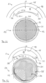
- Figure 12 shows a representation which in its upper part is of the type of view of the Figure 5
- a top view 33 of the lenticule surface 20 is shown, which is only illustrated by a cutting line 20.1 in the sectional view above.
- the flap surface 19 and the lenticule surface 20 are created in the cornea 5 in the manner described.
- a correction surface is created that is not rotationally symmetrical, since it is intended to correct higher aberrations, i.e. the curvature of the front side 15 of the cornea 5 after the removal of the volume 18 is not only to be changed in terms of sphericity.
- This correction surface is created, as the top view 33 of the lenticule surface 20 shows, by a spiral 32 that runs from the inside of the correction surface to the outside.
- the spiral defines a trajectory for adjusting the position of the laser beam focus.
- the center of the spiral is preferably (but not necessarily) at the highest point of the correction surface.
- the spiral is based on contour lines, whereby the z-position (position along the main direction of incidence A of the laser radiation) of the focus position is continuously adjusted. Instead of a group of closed scan lines that never intersect, there is a continuous scan line.
- Local, position-dependent refractive power corrections B(r, ⁇ ) can be easily represented and generated by modulating the angle-dependent radial function r( ⁇ ) by such a radially "deformed" spiral.
- the edge line of the lenticule surface 20 should be a circular line that lies in a plane in the z direction, which, as usual, is the main direction of incidence A of the laser radiation being processed.
- z constant.
- the correction surface required for the optical correction is defined in a correction area 34.
- the trajectory is shown as a solid line.
- the edge of this correction area is of course not rotationally symmetrical - but it is flat, since the spiral is based on contour lines.
- the spiral is therefore modified in a transition area 35 in such a way that within a limited number of revolutions the angle-dependent trajectory distance is modulated so that the non-rotationally symmetrical edge of the correction surface turns into a circle.
- the radial modulation is therefore reduced to zero over a certain number of revolutions. For example, this can be done by choosing the number of revolutions of the spiral in the transition area so that it corresponds to the quotient of the radius difference and the desired distance between the spiral paths.
- the radius difference is the difference between the minimum radius of the correction surface and the radius of the desired circular edge, which is preferably equal to the maximum radius of the correction surface or only slightly larger.
- the correction surface which is the cutting surface geometry in the correction area 34, is continued in such a way that it ends in a circular edge.
- This can be clearly seen in the proportions of the sectional representations, in which dot-dash reference lines are drawn for clarity.
- the continuation of the correction surface in the transition area in the sectional representation is shown with the same dashed line, as are the corresponding spiral turns in the top view 33 of the lenticule surface 20.
- the sectional view shows that the ends of the lenticule surface 20 lie in one plane. Furthermore, they are circular.
- the connection between the lenticule surface 20 and the spherical flap surface 19 can therefore be made with a simple, circular cone-shaped lenticule edge surface 30.
- transition region 35 and the lenticule edge region 31 (corresponding to the cutting surfaces 36 and 30).
- the transition zone adapts the otherwise non-rotationally symmetrical correction surface so that the lenticule surface 20 as a whole has a rotationally symmetrical edge.
- This edge is not lower, i.e. more posterior than that for the correction surface (corresponding to the cutting line), but also not higher, i.e. more anterior.
- the plane in which the circular edge is formed by the transition region 35 therefore intersects the correction surface or is at least at the maximum or minimum of this surface.
- the correction surface is thus supplemented by the transition zone, but is to be distinguished from the lenticule edge surface, which, as a simple circular cylinder or cone-shaped cutting surface, forms the connection between two rotationally symmetrical edges, namely that of the lenticule surface 20, which was reached by the transition zone 35, and that of the flap surface 19 (which is already spherical in the embodiment described).
- Figure 12 shows an embodiment in which the transition zone 35 provides a continuous and smooth, e.g. differentiable, adjustment between the edge surface of the correction surface (cutting surface in the correction zone 34) and the circular edge.
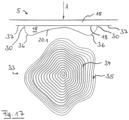
- a smooth progression is not absolutely necessary, as Figure 14 shows.
- the correction zone 34 is in this case predetermined by the correction surface, which is designed as an ellipsoid for astigmatism correction, for example.
- the sectional view of the lenticule surface 20 therefore shows two sections 20.1 and 20.2, which correspond to the semi-axes H1 and H2 of the ellipsoid surface in the correction zone 34.
- a different way is now also chosen to supplement the correction zone 34 with the transition zone 35 so that overall a rotationally symmetrical, i.e. circular, edge is present.
- the lenticule surface 20 is again created by a spiral path along which the focus of the laser radiation is deflected, as can be seen from the top view 33.
- the spiral course of the path is switched to a circular spiral with a constant z-value.
- the transition zone 35 There is therefore a spiral with a constant path distance in the transition zone 35, which is guided from the smallest radius of the correction surface in the correction zone 34 to the radius of the rotationally symmetrical edge, which is expediently set equal to the largest radius of the edge of the correction zone 34. If necessary, however, the transition zone can still receive a certain addition, i.e. the radius of the rotationally symmetrical edge can be selected to be one additional dimension larger than the largest radius of the correction surface in the correction zone 34.
- transition cutting surface 36 naturally depends on the distance of the edge of the non-rotationally symmetrical correction surface or correction zone 34 from the rotationally symmetrical edge. This leads to the transition cutting surface 36 on the right-hand side being in Figure 14 in the sectional view is much longer than on the left side, where it is almost point-shaped, since the rotationally symmetrical edge was chosen to be almost equal to the maximum radius of the correction zone 34.
- Figure 14 essentially corresponds to that of the Figure 13
- the correction surface or the correction zone 34 is not ellipsoidal here, i.e. not elliptical in the top view 33, but is designed to correct higher aberrations. Otherwise, the above applies to Figure 13 said applies without restriction also to the Figure 14 , which shows that the concept of the transition zone of Figure 13 does not necessarily have to be connected to an ellipsoidal correction surface.
- Figure 15 shows an embodiment in which the cornea 5 is applanated using a flat contact glass.
- the flap surface 19 is therefore designed as a plane.
- the lenticule edge zone 31 also appears only as a line in the top view 33.
- the transition zone 35 is analogous to the embodiment of the Figures 13 and 14 as a flat spiral with a constant orbit radius. Figures 13 and 14 explained therefore applies to the same extent.
- the transition zone 35 is therefore a planar spiral with a constant orbital distance, which runs from the minor semi-axis H1 to the major semi-axis H2 of the elliptical correction zone 34 in order to reach the circular edge.
- the lenticule edge surface is designed as a circular cylinder, in which it is ensured that the edge radius of the flap surface 19 is equal to the edge radius of the lenticule surface 20 and that the edges lie exactly one below the other.
- this is not absolutely necessary. Different radii can be used, and the circular edges can also be offset from one another. In this case, circular inclined cylinders or inclined cone surfaces are required for the lenticule surface.
- Figure 16 shows an embodiment not belonging to the invention of the first variant, in which no transition zone 35 is provided. Instead, a correspondingly non-rotationally symmetrical lenticule edge surface 30 is formed directly from the non-rotationally symmetrical edge of the correction zone 34 to the flap surface 19. This surface is then a cylindrical surface, the generatrix of which corresponds to the edge of the correction zone 34.
- the invention of the first variant does not realize the embodiment of the Figure 17 , in which a transition zone 35 is provided which continues the correction zone 34 by reducing the z-coordinate in such a way that the transition zone 35 is guided directly to the flap surface 19 while maintaining the non-rotationally symmetrical circumference.
- the transition zone is thus now generated in such a way that within a limited number of revolutions the angle-dependent path distance is modulated in such a way that the edge of the correction zone 34 is brought closer to the flap surface 19 with regard to the z-coordinate.
- control data for the operation of the device described here can be used for almost any surgical procedure in which a volume is removed from the cornea of the eye by means of a device under the control of control data or is added to it, as already explained in the general part of the description.
Landscapes
- Health & Medical Sciences (AREA)
- Ophthalmology & Optometry (AREA)
- Heart & Thoracic Surgery (AREA)
- Vascular Medicine (AREA)
- Optics & Photonics (AREA)
- Surgery (AREA)
- Engineering & Computer Science (AREA)
- Biomedical Technology (AREA)
- Physics & Mathematics (AREA)
- Nuclear Medicine, Radiotherapy & Molecular Imaging (AREA)
- Life Sciences & Earth Sciences (AREA)
- Animal Behavior & Ethology (AREA)
- General Health & Medical Sciences (AREA)
- Public Health (AREA)
- Veterinary Medicine (AREA)
- Laser Surgery Devices (AREA)
Applications Claiming Priority (5)
| Application Number | Priority Date | Filing Date | Title |
|---|---|---|---|
| DE102009005482A DE102009005482A1 (de) | 2009-01-21 | 2009-01-21 | Vorrichtung und Verfahren zum Erzeugen von Steuerdaten zur operativen Fehlsichtigkeitskorrektur eines Auges |
| EP21190371.1A EP3925584B1 (fr) | 2009-01-21 | 2010-01-21 | Dispositif et procédé de production de données de commande pour la correction opératoire d'un défaut de vision d'un oeil |
| EP10716495.6A EP2389148B1 (fr) | 2009-01-21 | 2010-01-21 | Dispositif et procédé de production de données de commande pour la correction opératoire d'un défaut de vision d'un oeil |
| PCT/EP2010/050700 WO2010084162A2 (fr) | 2009-01-21 | 2010-01-21 | Dispositif et procédé de production de données de commande pour la correction opératoire d'un défaut de vision d'un oeil |
| EP18157424.5A EP3363416B1 (fr) | 2009-01-21 | 2010-01-21 | Dispositif et procédé de production de données de commande pour la correction opératoire d'un défaut de vision d'un oeil |
Related Parent Applications (3)
| Application Number | Title | Priority Date | Filing Date |
|---|---|---|---|
| EP21190371.1A Division EP3925584B1 (fr) | 2009-01-21 | 2010-01-21 | Dispositif et procédé de production de données de commande pour la correction opératoire d'un défaut de vision d'un oeil |
| EP10716495.6A Division EP2389148B1 (fr) | 2009-01-21 | 2010-01-21 | Dispositif et procédé de production de données de commande pour la correction opératoire d'un défaut de vision d'un oeil |
| EP18157424.5A Division EP3363416B1 (fr) | 2009-01-21 | 2010-01-21 | Dispositif et procédé de production de données de commande pour la correction opératoire d'un défaut de vision d'un oeil |
Publications (2)
| Publication Number | Publication Date |
|---|---|
| EP4477196A2 true EP4477196A2 (fr) | 2024-12-18 |
| EP4477196A3 EP4477196A3 (fr) | 2025-01-22 |
Family
ID=42091503
Family Applications (5)
| Application Number | Title | Priority Date | Filing Date |
|---|---|---|---|
| EP10716495.6A Active EP2389148B1 (fr) | 2009-01-21 | 2010-01-21 | Dispositif et procédé de production de données de commande pour la correction opératoire d'un défaut de vision d'un oeil |
| EP10702268.3A Active EP2389147B1 (fr) | 2009-01-21 | 2010-01-21 | Dispositif et procédé de production de données de commande pour la correction opératoire d'un défaut de vision d'un oeil |
| EP24204715.7A Pending EP4477196A3 (fr) | 2009-01-21 | 2010-01-21 | Dispositif et procédé de production de données de commande pour la correction opératoire d'un défaut de vision d'un oeil |
| EP21190371.1A Active EP3925584B1 (fr) | 2009-01-21 | 2010-01-21 | Dispositif et procédé de production de données de commande pour la correction opératoire d'un défaut de vision d'un oeil |
| EP18157424.5A Active EP3363416B1 (fr) | 2009-01-21 | 2010-01-21 | Dispositif et procédé de production de données de commande pour la correction opératoire d'un défaut de vision d'un oeil |
Family Applications Before (2)
| Application Number | Title | Priority Date | Filing Date |
|---|---|---|---|
| EP10716495.6A Active EP2389148B1 (fr) | 2009-01-21 | 2010-01-21 | Dispositif et procédé de production de données de commande pour la correction opératoire d'un défaut de vision d'un oeil |
| EP10702268.3A Active EP2389147B1 (fr) | 2009-01-21 | 2010-01-21 | Dispositif et procédé de production de données de commande pour la correction opératoire d'un défaut de vision d'un oeil |
Family Applications After (2)
| Application Number | Title | Priority Date | Filing Date |
|---|---|---|---|
| EP21190371.1A Active EP3925584B1 (fr) | 2009-01-21 | 2010-01-21 | Dispositif et procédé de production de données de commande pour la correction opératoire d'un défaut de vision d'un oeil |
| EP18157424.5A Active EP3363416B1 (fr) | 2009-01-21 | 2010-01-21 | Dispositif et procédé de production de données de commande pour la correction opératoire d'un défaut de vision d'un oeil |
Country Status (10)
| Country | Link |
|---|---|
| US (7) | US9050172B2 (fr) |
| EP (5) | EP2389148B1 (fr) |
| JP (2) | JP6025331B2 (fr) |
| CN (1) | CN102292055B (fr) |
| DE (1) | DE102009005482A1 (fr) |
| DK (1) | DK2389148T3 (fr) |
| ES (1) | ES2670408T3 (fr) |
| PL (1) | PL2389148T3 (fr) |
| PT (1) | PT2389148T (fr) |
| WO (2) | WO2010084163A1 (fr) |
Families Citing this family (43)
| Publication number | Priority date | Publication date | Assignee | Title |
|---|---|---|---|---|
| JPH0825612B2 (ja) | 1985-09-30 | 1996-03-13 | 日本電気株式会社 | コンベアストツパの制御方法 |
| JP3159472B2 (ja) | 1991-07-11 | 2001-04-23 | 松下電器産業株式会社 | 重量物の搬送装置 |
| US8685006B2 (en) * | 2006-11-10 | 2014-04-01 | Carl Zeiss Meditec Ag | Treatment apparatus for surgical correction of defective eyesight, method of generating control data therefore, and method for surgical correction of defective eyesight |
| DE102009005482A1 (de) * | 2009-01-21 | 2010-07-22 | Carl Zeiss Meditec Ag | Vorrichtung und Verfahren zum Erzeugen von Steuerdaten zur operativen Fehlsichtigkeitskorrektur eines Auges |
| US11771596B2 (en) | 2010-05-10 | 2023-10-03 | Ramot At Tel-Aviv University Ltd. | System and method for treating an eye |
| EP3797743A3 (fr) | 2010-05-10 | 2021-07-21 | Ramot at Tel Aviv University, Ltd. | Système et procédé de traitement d'un oeil |
| DE102011075799A1 (de) | 2011-05-13 | 2012-11-15 | Carl Zeiss Meditec Ag | Optisches System für ein Lasertherapiegerät |
| JP5838598B2 (ja) * | 2011-05-31 | 2016-01-06 | 株式会社ニデック | 眼科用レーザ手術装置 |
| DE102011083928A1 (de) * | 2011-09-30 | 2013-04-04 | Carl Zeiss Meditec Ag | Behandlungsvorrichtung zur operativen Fehlsichtigkeitskorrektur eines Auges, Verfahren zum Erzeugen von Steuerdaten dafür und Verfahren zur operativen Fehlsichtigkeitskorrektur eines Auges |
| TWI588560B (zh) | 2012-04-05 | 2017-06-21 | 布萊恩荷登視覺協會 | 用於屈光不正之鏡片、裝置、方法及系統 |
| DE102013218415A1 (de) | 2012-09-14 | 2014-04-10 | Carl Zeiss Meditec Ag | Augenchirurgisches Verfahren |
| US9201250B2 (en) | 2012-10-17 | 2015-12-01 | Brien Holden Vision Institute | Lenses, devices, methods and systems for refractive error |
| SG11201502115RA (en) | 2012-10-17 | 2015-05-28 | Holden Brien Vision Inst | Lenses, devices, methods and systems for refractive error |
| JP2015533322A (ja) * | 2012-11-08 | 2015-11-24 | カール ツアイス メディテック アクチエンゲゼルシャフト | 眼の角膜の総屈折力を算定するための方法 |
| US10709611B2 (en) * | 2014-09-25 | 2020-07-14 | Amo Development, Llc | Systems and methods for lenticular laser incision |
| AU2015320445B2 (en) | 2014-09-25 | 2020-06-25 | Amo Development, Llc | Systems for lenticular laser incision |
| CA2976025A1 (fr) * | 2015-02-06 | 2016-08-11 | Optimedica Corporation | Traitement de chirurgie oculaire au laser en boucle fermee |
| DE102016208011A1 (de) | 2016-05-10 | 2017-11-16 | Carl Zeiss Meditec Ag | Augenchirurgisches Verfahren |
| DE102016116267B4 (de) | 2016-08-01 | 2025-11-13 | Carl Zeiss Meditec Ag | Vorrichtung zur operativen Fehlsichtigkeitskorrektur eines Auges und Verfahren zum Erzeugen von Steuerdaten hierfür |
| WO2018144644A1 (fr) | 2017-01-31 | 2018-08-09 | Optimedica Corporation | Procédés et systèmes pour chirurgie ophtalmique au laser qui permettent des expositions de l'iris sous une limite d'exposition prédéfinie |
| DE102017207529A1 (de) * | 2017-05-04 | 2018-11-08 | Carl Zeiss Meditec Ag | Nachbehandlung bei augenchirurgischer Refraktionskorrektur |
| EP3817698A4 (fr) | 2018-07-02 | 2022-03-30 | Belkin Laser Ltd. | Trabéculoplastie laser sélective directe |
| WO2020089737A1 (fr) | 2018-10-28 | 2020-05-07 | Belkin Laser Ltd. | Protection pour trabéculoplastie laser sélective directe |
| DE102019103851B4 (de) * | 2019-02-15 | 2023-03-09 | Schwind Eye-Tech-Solutions Gmbh | Verfahren zur Steuerung eines augenchirurgischen Lasers und Behandlungsvorrichtung |
| US11110007B2 (en) * | 2019-03-15 | 2021-09-07 | Amo Development, Llc | Ophthalmic laser surgical method and system for forming corneal lenticule with side tab for easy extraction |
| DE112020001935T5 (de) * | 2019-04-15 | 2022-01-13 | Carl Zeiss Meditec Ag | Vorrichtungen und Verfahren für Laserchirurgie am Auge, insbesondere für Keratoplastik |
| DE102019133428B3 (de) * | 2019-12-06 | 2021-03-25 | Schwind Eye-Tech-Solutions Gmbh | Verfahren zur Steuerung eines augenchirurgischen Lasers mit einer Übergangszone am Volumenkörper |
| DE102020104687B4 (de) | 2020-02-21 | 2024-02-15 | Schwind Eye-Tech-Solutions Gmbh | Verfahren zur Steuerung eines augenchirurgischen Lasers, sowie Behandlungsvorrichtung |
| DE102020112583B4 (de) | 2020-05-08 | 2024-02-15 | Schwind Eye-Tech-Solutions Gmbh | Verfahren zur Steuerung eines augenchirurgischen Lasers und Behandlungsvorrichtung |
| DE102020113820A1 (de) | 2020-05-22 | 2021-11-25 | Schwind Eye-Tech-Solutions Gmbh | Verfahren zum Bereitstellen von Steuerdaten für einen augenchirurgischen Laser einer Behandlungsvorrichtung |
| DE102020113819A1 (de) * | 2020-05-22 | 2021-11-25 | Schwind Eye-Tech-Solutions Gmbh | Verfahren zum Bereitstellen von Steuerdaten für einen augenchirurgischen Laser einer Behandlungsvorrichtung |
| EP4157172A1 (fr) * | 2020-05-27 | 2023-04-05 | Alcon Inc. | Procédé de correction d'aberrations d'ordre supérieur à l'aide d'une correction de vision laser |
| DE102020114791B4 (de) | 2020-06-04 | 2024-06-27 | Schwind Eye-Tech-Solutions Gmbh | Verfahren zur Steuerung eines augenchirurgischen Lasers und Behandlungsvorrichtung |
| US12396886B2 (en) | 2020-07-19 | 2025-08-26 | Belkin Vision Ltd. | Automated capsulotomy |
| CN113907947B (zh) * | 2020-08-04 | 2024-11-15 | 施温德眼科技术解决方式有限公司 | 用于控制眼科手术激光器的方法及治疗设备 |
| US12564517B2 (en) | 2020-10-26 | 2026-03-03 | Belvin Vision Ltd. | Avoiding blood vessels during direct selective laser trabeculoplasty |
| DE102020128625B4 (de) * | 2020-10-30 | 2025-09-04 | Schwind Eye-Tech-Solutions Gmbh | Verfahren zum Bereitstellen von Steuerdaten für einen augenchirurgischen Laser einer Behandlungsvorrichtung, Steuereinrichtung und Behandlungsvorrichtung |
| DE102020133189B4 (de) * | 2020-12-11 | 2024-07-18 | Schwind Eye-Tech-Solutions Gmbh | Verfahren zur Steuerung eines augenchirurgischen Lasers und Behandlungsvorrichtung |
| US12303433B2 (en) * | 2021-04-19 | 2025-05-20 | Ziemer Ophthalmic Systems Ag | Ophthalmological device for refractive correction of a cornea |
| US12121476B2 (en) | 2022-04-06 | 2024-10-22 | Amo Development, Llc | Corneal lenticular incision using a femtosecond laser with smooth scanning trajectory connecting multiple sweeps |
| DE102022112296A1 (de) * | 2022-05-17 | 2023-11-23 | Schwind Eye-Tech-Solutions Gmbh | Verfahren zum Bereitstellen von Steuerdaten für einen Laser einer Behandlungsvorrichtung |
| JP2025534703A (ja) | 2022-10-11 | 2025-10-17 | ベルキン ビジョン リミティド | 自動選択的レーザ線維柱帯形成術 |
| DE102023208088A1 (de) | 2023-08-24 | 2025-02-27 | Carl Zeiss Meditec Ag | Verfahren und Vorrichtung zur Erzeugung von Steuerdaten mit einer optimierten Schnittgeometrie und Schnittreihenfolge für eine Korrektur der Refraktion eines Auges |
Citations (16)
| Publication number | Priority date | Publication date | Assignee | Title |
|---|---|---|---|---|
| WO1996011655A1 (fr) | 1994-10-14 | 1996-04-25 | Chiron/Technolas Gmbh Ophthalmologische Systeme | Systeme de laser a excimere pour la correction de la vision |
| US5549632A (en) | 1992-10-26 | 1996-08-27 | Novatec Laser Systems, Inc. | Method and apparatus for ophthalmic surgery |
| DE69500997T2 (de) | 1994-04-08 | 1998-04-30 | Univ Michigan | Verfahren zum konfigurationsteuern von laserinduziertem zerstören und abtragen |
| US5993438A (en) | 1993-11-12 | 1999-11-30 | Escalon Medical Corporation | Intrastromal photorefractive keratectomy |
| US6110166A (en) | 1995-03-20 | 2000-08-29 | Escalon Medical Corporation | Method for corneal laser surgery |
| EP1153584A1 (fr) | 1999-10-21 | 2001-11-14 | Nidek Co., Ltd. | Dispositif pour determiner la quantite de cornee a enlever et dispositif de chirurgie corneenne |
| EP1159986A2 (fr) | 1991-11-06 | 2001-12-05 | LAI, Shui, T. | Procédé et dispositif utilisés pour la chirurgie cornéenne |
| WO2004032810A2 (fr) | 2002-10-11 | 2004-04-22 | Intralase Corp. | Procede et systeme de determination de la position et de l'alignement de la surface d'un objet par rapport a un faisceau laser |
| WO2005011547A1 (fr) | 2003-07-25 | 2005-02-10 | Carl Zeiss Meditec Ag | Dispositif et procede pour former des surfaces de coupe courbes dans une matiere transparente |
| DE10358927A1 (de) | 2003-12-16 | 2005-07-21 | Carl Zeiss Meditec Ag | Laservorrichtung und Verfahren zur Materialbearbeitung mittels Laserstrahlung |
| WO2005092172A1 (fr) | 2004-03-03 | 2005-10-06 | Visx, Incorporated | Procedes de transformation de cartes de fronts d'ondes d'une distance verre-oeil a une autre |
| US7131968B2 (en) | 2003-06-02 | 2006-11-07 | Carl Zeiss Meditec Ag | Apparatus and method for opthalmologic surgical procedures using a femtosecond fiber laser |
| DE102006053119A1 (de) | 2006-11-10 | 2008-05-15 | Carl Zeiss Meditec Ag | Behandlungsvorrichtung zur operativen Fehlsichtigkeitskorrektur eines Auges, Verfahren zum Erzeugen von Steuerdaten dafür und Verfahren zur operativen Fehlsichtigkeitskorrektur |
| DE102006053120A1 (de) | 2006-11-10 | 2008-05-15 | Carl Zeiss Meditec Ag | Behandlungsvorrichtung zur operativen Fehlsichtigkeitskorrektur eines Auges, Verfahren zum Erzeugen von Steuerdaten dafür und Verfahren zur operativen Fehlsichtigkeitskorrektur eines Auges |
| DE102006053118A1 (de) | 2006-11-10 | 2008-05-15 | Carl Zeiss Meditec Ag | Planungseinrichtung zum Vorbereiten von Steuerdaten für eine Behandlungsvorrichtung zur operativen Fehlsichtigkeitskorrektur, Behandlungsvorrichtung zur operativen Fehlsichtigkeitskorrektur und Verfahren zum Vorbereiten von Steuerdaten dafür |
| DE102007053281A1 (de) | 2007-11-08 | 2009-05-14 | Carl Zeiss Meditec Ag | Behandlungsvorrichtung zur operativen Fehlsichtigkeitskorrektur eines Auges, Verfahren zum Erzeugen von Steuerdaten dafür und Verfahren zur operativen Fehlsichtigkeitskorrektur eines Auges |
Family Cites Families (35)
| Publication number | Priority date | Publication date | Assignee | Title |
|---|---|---|---|---|
| US6099522A (en) * | 1989-02-06 | 2000-08-08 | Visx Inc. | Automated laser workstation for high precision surgical and industrial interventions |
| US5891131A (en) * | 1993-02-01 | 1999-04-06 | Arizona Board Of Regents | Method and apparatus for automated simulation and design of corneal refractive procedures |
| JP2862202B2 (ja) * | 1994-04-28 | 1999-03-03 | 株式会社ニデック | 角膜レ−ザ手術装置 |
| US5906608A (en) * | 1996-01-31 | 1999-05-25 | Nidek Co., Ltd. | Ablation apparatus |
| US5843070A (en) * | 1996-05-13 | 1998-12-01 | Partech, Inc. | Simulating corneal laser surgery |
| US5907388A (en) * | 1996-10-03 | 1999-05-25 | Nidek Co., Ltd. | Ophthalmic measurement apparatus having plural pairs of photoreceiving elements |
| CA2306864C (fr) * | 1998-03-04 | 2012-05-15 | Visx, Incorporated | Systeme de traitement laser de la presbytie en utilisant une image decentree |
| US6033075A (en) * | 1998-03-31 | 2000-03-07 | Nidek Co., Ltd. | Ophthalmic apparatus |
| JP3848492B2 (ja) * | 1998-09-04 | 2006-11-22 | 株式会社ニデック | 角膜手術装置 |
| WO2000041660A1 (fr) * | 1999-01-15 | 2000-07-20 | Medjet, Inc. | Outil coupant corneen a microjet avec gabarit d'aplanissement reglable |
| US6648877B1 (en) * | 2000-06-30 | 2003-11-18 | Intralase Corp. | Method for custom corneal corrections |
| JP3860405B2 (ja) | 2000-09-29 | 2006-12-20 | 株式会社ニデック | 角膜手術装置 |
| US20030014042A1 (en) * | 2001-07-13 | 2003-01-16 | Tibor Juhasz | Method of creating stromal pockets for corneal implants |
| AU2003219975A1 (en) | 2002-03-04 | 2003-09-22 | The Cleveland Clinic Foundation | Method and apparatus for controlling ablation in refractive surgery |
| DK1487368T3 (da) | 2002-03-23 | 2007-10-22 | Intralase Corp | Anlæg til forbedret materialebearbejdning under anvendelse af en laserstråle |
| US7130835B2 (en) * | 2002-03-28 | 2006-10-31 | Bausch & Lomb Incorporated | System and method for predictive ophthalmic correction |
| US7434936B2 (en) | 2002-12-06 | 2008-10-14 | Amo Manufacturing Usa, Llc | Residual accommodation threshold for correction of presbyopia and other presbyopia correction using patient data |
| MXPA05006000A (es) | 2002-12-06 | 2005-08-18 | Visx Inc | Correccion de presbiopia utilizando datos del paciente. |
| US7164088B1 (en) | 2003-03-16 | 2007-01-16 | Palm, Inc. | Method and apparatus to improve tactile feel for keyboards and button assemblies |
| DE10334108B4 (de) | 2003-07-25 | 2018-05-09 | Carl Zeiss Meditec Ag | Vorrichtung zum Ausbilden einer geschlossenen, gekrümmten Schnittfläche |
| DE102005013558A1 (de) * | 2005-03-23 | 2006-09-28 | Carl Zeiss Meditec Ag | Verfahren und Vorrichtung zur Erhöhung der Tiefenschärfe eines optischen Systems |
| JP5031747B2 (ja) | 2005-08-25 | 2012-09-26 | カール ツァイス メディテック アクチエンゲゼルシャフト | 眼科手術用のコンタクト・レンズ |
| US9248047B2 (en) * | 2006-01-23 | 2016-02-02 | Ziemer Holding Ag | System for protecting tissue in the treatment of eyes |
| US8182471B2 (en) * | 2006-03-17 | 2012-05-22 | Amo Manufacturing Usa, Llc. | Intrastromal refractive correction systems and methods |
| US20080082088A1 (en) * | 2006-09-05 | 2008-04-03 | Intralase Corp. | System and method for resecting corneal tissue |
| EP2086483B1 (fr) * | 2006-11-10 | 2016-03-16 | Carl Zeiss Meditec AG | Dispositif de traitement de correction d'un défaut visuel de l'oeil par opération et procédé de production de données de commande pour ce dispositif |
| EP2529712B9 (fr) | 2006-11-10 | 2014-09-10 | Carl Zeiss Meditec AG | Dispositif de traitement de correction d'un défaut visuel de l'oeil par opération et procédé de production de données de commande pour ce dispositif |
| EP3831348B1 (fr) | 2006-11-10 | 2024-01-10 | Carl Zeiss Meditec AG | Dispositif de traitement laser destiné à la correction opérationnelle des troubles de la vue |
| US8685006B2 (en) * | 2006-11-10 | 2014-04-01 | Carl Zeiss Meditec Ag | Treatment apparatus for surgical correction of defective eyesight, method of generating control data therefore, and method for surgical correction of defective eyesight |
| DE102007019813A1 (de) * | 2007-04-26 | 2008-10-30 | Carl Zeiss Meditec Ag | Vorrichtung und Verfahren zum Erzeugen von Schnittflächen in der Hornhaut eines Auges zur Fehlsichtigkeitskorrektur |
| US9456925B2 (en) * | 2007-09-06 | 2016-10-04 | Alcon Lensx, Inc. | Photodisruptive laser treatment of the crystalline lens |
| DE102007053283B4 (de) | 2007-11-08 | 2019-08-29 | Carl Zeiss Meditec Ag | Behandlungsvorrichtung zur operativen Fehlsichtigkeitskorrektur eines Auges und Verfahren zum Erzeugen von Steuerdaten dafür |
| DE102008017293B4 (de) | 2008-04-04 | 2019-11-14 | Carl Zeiss Meditec Ag | Verfahren zum Erzeugen von Steuerdaten für die Augenchirurgie sowie augenchirurgische Behandlungsvorrichtung und -verfahren |
| DE102009005482A1 (de) * | 2009-01-21 | 2010-07-22 | Carl Zeiss Meditec Ag | Vorrichtung und Verfahren zum Erzeugen von Steuerdaten zur operativen Fehlsichtigkeitskorrektur eines Auges |
| US9411938B2 (en) * | 2009-04-02 | 2016-08-09 | Sie Ag, Surgical Instrument Engineering | System for defining cuts in eye tissue |
-
2009
- 2009-01-21 DE DE102009005482A patent/DE102009005482A1/de active Pending
-
2010
- 2010-01-21 CN CN2010800051840A patent/CN102292055B/zh active Active
- 2010-01-21 PT PT107164956T patent/PT2389148T/pt unknown
- 2010-01-21 WO PCT/EP2010/050701 patent/WO2010084163A1/fr not_active Ceased
- 2010-01-21 ES ES10716495.6T patent/ES2670408T3/es active Active
- 2010-01-21 WO PCT/EP2010/050700 patent/WO2010084162A2/fr not_active Ceased
- 2010-01-21 DK DK10716495.6T patent/DK2389148T3/en active
- 2010-01-21 EP EP10716495.6A patent/EP2389148B1/fr active Active
- 2010-01-21 JP JP2011546792A patent/JP6025331B2/ja active Active
- 2010-01-21 US US13/145,761 patent/US9050172B2/en active Active
- 2010-01-21 PL PL10716495T patent/PL2389148T3/pl unknown
- 2010-01-21 EP EP10702268.3A patent/EP2389147B1/fr active Active
- 2010-01-21 EP EP24204715.7A patent/EP4477196A3/fr active Pending
- 2010-01-21 US US13/145,759 patent/US10179069B2/en active Active
- 2010-01-21 EP EP21190371.1A patent/EP3925584B1/fr active Active
- 2010-01-21 EP EP18157424.5A patent/EP3363416B1/fr active Active
-
2015
- 2015-04-02 JP JP2015075835A patent/JP6419632B2/ja active Active
- 2015-05-08 US US14/707,578 patent/US10828197B2/en active Active
-
2019
- 2019-01-14 US US16/247,027 patent/US11413189B2/en active Active
-
2020
- 2020-11-06 US US17/091,960 patent/US12076275B2/en active Active
-
2022
- 2022-07-08 US US17/811,463 patent/US12220351B2/en active Active
-
2024
- 2024-07-31 US US18/789,935 patent/US20250032318A1/en active Pending
Patent Citations (18)
| Publication number | Priority date | Publication date | Assignee | Title |
|---|---|---|---|---|
| EP1159986A2 (fr) | 1991-11-06 | 2001-12-05 | LAI, Shui, T. | Procédé et dispositif utilisés pour la chirurgie cornéenne |
| US5549632A (en) | 1992-10-26 | 1996-08-27 | Novatec Laser Systems, Inc. | Method and apparatus for ophthalmic surgery |
| US5993438A (en) | 1993-11-12 | 1999-11-30 | Escalon Medical Corporation | Intrastromal photorefractive keratectomy |
| DE69500997T2 (de) | 1994-04-08 | 1998-04-30 | Univ Michigan | Verfahren zum konfigurationsteuern von laserinduziertem zerstören und abtragen |
| WO1996011655A1 (fr) | 1994-10-14 | 1996-04-25 | Chiron/Technolas Gmbh Ophthalmologische Systeme | Systeme de laser a excimere pour la correction de la vision |
| US6110166A (en) | 1995-03-20 | 2000-08-29 | Escalon Medical Corporation | Method for corneal laser surgery |
| EP1153584A1 (fr) | 1999-10-21 | 2001-11-14 | Nidek Co., Ltd. | Dispositif pour determiner la quantite de cornee a enlever et dispositif de chirurgie corneenne |
| WO2004032810A2 (fr) | 2002-10-11 | 2004-04-22 | Intralase Corp. | Procede et systeme de determination de la position et de l'alignement de la surface d'un objet par rapport a un faisceau laser |
| US7131968B2 (en) | 2003-06-02 | 2006-11-07 | Carl Zeiss Meditec Ag | Apparatus and method for opthalmologic surgical procedures using a femtosecond fiber laser |
| DE10334110A1 (de) | 2003-07-25 | 2005-02-17 | Carl Zeiss Meditec Ag | Vorrichtung und Verfahren zum Ausbilden gekrümmter Schnittflächen in einem transparenten Material |
| WO2005011547A1 (fr) | 2003-07-25 | 2005-02-10 | Carl Zeiss Meditec Ag | Dispositif et procede pour former des surfaces de coupe courbes dans une matiere transparente |
| DE10358927A1 (de) | 2003-12-16 | 2005-07-21 | Carl Zeiss Meditec Ag | Laservorrichtung und Verfahren zur Materialbearbeitung mittels Laserstrahlung |
| US20080021443A1 (en) | 2003-12-16 | 2008-01-24 | Mark Bischoff | Laser Device and Method for Machining Material Using Laser Radiation |
| WO2005092172A1 (fr) | 2004-03-03 | 2005-10-06 | Visx, Incorporated | Procedes de transformation de cartes de fronts d'ondes d'une distance verre-oeil a une autre |
| DE102006053119A1 (de) | 2006-11-10 | 2008-05-15 | Carl Zeiss Meditec Ag | Behandlungsvorrichtung zur operativen Fehlsichtigkeitskorrektur eines Auges, Verfahren zum Erzeugen von Steuerdaten dafür und Verfahren zur operativen Fehlsichtigkeitskorrektur |
| DE102006053120A1 (de) | 2006-11-10 | 2008-05-15 | Carl Zeiss Meditec Ag | Behandlungsvorrichtung zur operativen Fehlsichtigkeitskorrektur eines Auges, Verfahren zum Erzeugen von Steuerdaten dafür und Verfahren zur operativen Fehlsichtigkeitskorrektur eines Auges |
| DE102006053118A1 (de) | 2006-11-10 | 2008-05-15 | Carl Zeiss Meditec Ag | Planungseinrichtung zum Vorbereiten von Steuerdaten für eine Behandlungsvorrichtung zur operativen Fehlsichtigkeitskorrektur, Behandlungsvorrichtung zur operativen Fehlsichtigkeitskorrektur und Verfahren zum Vorbereiten von Steuerdaten dafür |
| DE102007053281A1 (de) | 2007-11-08 | 2009-05-14 | Carl Zeiss Meditec Ag | Behandlungsvorrichtung zur operativen Fehlsichtigkeitskorrektur eines Auges, Verfahren zum Erzeugen von Steuerdaten dafür und Verfahren zur operativen Fehlsichtigkeitskorrektur eines Auges |
Also Published As
Similar Documents
| Publication | Publication Date | Title |
|---|---|---|
| EP3925584B1 (fr) | Dispositif et procédé de production de données de commande pour la correction opératoire d'un défaut de vision d'un oeil | |
| EP2211803B1 (fr) | Dispositif de traitement permettant la correction chirurgicale de l'amétropie d'un oeil et procédé de génération de données de commande associées | |
| EP2211804B1 (fr) | Dispositif de traitement permettant la correction chirurgicale de l'amétropie d'un oeil et procédé de génération de données de commande associées | |
| DE102016116267B4 (de) | Vorrichtung zur operativen Fehlsichtigkeitskorrektur eines Auges und Verfahren zum Erzeugen von Steuerdaten hierfür | |
| EP2136747B1 (fr) | Post-traitement lors d'une correction de la réfraction par chirurgie de l'oeil | |
| EP3831348B1 (fr) | Dispositif de traitement laser destiné à la correction opérationnelle des troubles de la vue | |
| EP3618787B1 (fr) | Post-traitement lors d'une correction de la réfraction par chirurgie de l'oeil | |
| EP3454802B1 (fr) | Dispositif de planification et procede de generation de donnees de commande pour un dispositif de chirurgie ophtalmique | |
| DE102012018421A1 (de) | Augenchirurgische Refraktionskorrektur | |
| EP3200737B1 (fr) | Dispositif de planification et procédé de génération de données de commande pour un dispositif de traitement chirurgical oculaire | |
| DE102013218415A1 (de) | Augenchirurgisches Verfahren | |
| DE102011083928A1 (de) | Behandlungsvorrichtung zur operativen Fehlsichtigkeitskorrektur eines Auges, Verfahren zum Erzeugen von Steuerdaten dafür und Verfahren zur operativen Fehlsichtigkeitskorrektur eines Auges | |
| DE102006053120A1 (de) | Behandlungsvorrichtung zur operativen Fehlsichtigkeitskorrektur eines Auges, Verfahren zum Erzeugen von Steuerdaten dafür und Verfahren zur operativen Fehlsichtigkeitskorrektur eines Auges | |
| DE102010031348B4 (de) | Steuerdatenerzeugung für die augenchirurgische Fehlsichtigkeitsbehandlung | |
| DE102007063962B4 (de) | Behandlungsvorrichtung zur operativen Fehlsichtigkeitskorrektur eines Auges und Verfahren zum Erzeugen von Steuerdaten dafür | |
| WO2025181293A1 (fr) | Dispositifs et procédé de génération de données de commande avec une géométrie de coupe optimisée pour des coupes de zone de bord pendant la correction de la réfraction d'un œil |
Legal Events
| Date | Code | Title | Description |
|---|---|---|---|
| PUAI | Public reference made under article 153(3) epc to a published international application that has entered the european phase |
Free format text: ORIGINAL CODE: 0009012 |
|
| STAA | Information on the status of an ep patent application or granted ep patent |
Free format text: STATUS: THE APPLICATION HAS BEEN PUBLISHED |
|
| AC | Divisional application: reference to earlier application |
Ref document number: 2389148 Country of ref document: EP Kind code of ref document: P Ref document number: 3363416 Country of ref document: EP Kind code of ref document: P Ref document number: 3925584 Country of ref document: EP Kind code of ref document: P |
|
| AK | Designated contracting states |
Kind code of ref document: A2 Designated state(s): AT BE BG CH CY CZ DE DK EE ES FI FR GB GR HR HU IE IS IT LI LT LU LV MC MK MT NL NO PL PT RO SE SI SK SM TR |
|
| REG | Reference to a national code |
Ref country code: DE Ref legal event code: R079 Free format text: PREVIOUS MAIN CLASS: A61F0009008000 Ipc: A61F0009010000 |
|
| PUAL | Search report despatched |
Free format text: ORIGINAL CODE: 0009013 |
|
| AK | Designated contracting states |
Kind code of ref document: A3 Designated state(s): AT BE BG CH CY CZ DE DK EE ES FI FR GB GR HR HU IE IS IT LI LT LU LV MC MK MT NL NO PL PT RO SE SI SK SM TR |
|
| RIC1 | Information provided on ipc code assigned before grant |
Ipc: A61F 9/009 20060101ALN20241218BHEP Ipc: A61F 9/008 20060101ALI20241218BHEP Ipc: A61F 9/01 20060101AFI20241218BHEP |
|
| STAA | Information on the status of an ep patent application or granted ep patent |
Free format text: STATUS: REQUEST FOR EXAMINATION WAS MADE |
|
| 17P | Request for examination filed |
Effective date: 20250718 |
|
| GRAP | Despatch of communication of intention to grant a patent |
Free format text: ORIGINAL CODE: EPIDOSNIGR1 |
|
| STAA | Information on the status of an ep patent application or granted ep patent |
Free format text: STATUS: GRANT OF PATENT IS INTENDED |
|
| RIC1 | Information provided on ipc code assigned before grant |
Ipc: A61F 9/01 20060101AFI20260210BHEP Ipc: A61F 9/008 20060101ALI20260210BHEP Ipc: A61F 9/009 20060101ALN20260210BHEP |
|
| INTG | Intention to grant announced |
Effective date: 20260316 |