EP4477203A1 - Masseur réglable en longueur basé sur une alimentation à induction sans fil - Google Patents
Masseur réglable en longueur basé sur une alimentation à induction sans fil Download PDFInfo
- Publication number
- EP4477203A1 EP4477203A1 EP23185981.0A EP23185981A EP4477203A1 EP 4477203 A1 EP4477203 A1 EP 4477203A1 EP 23185981 A EP23185981 A EP 23185981A EP 4477203 A1 EP4477203 A1 EP 4477203A1
- Authority
- EP
- European Patent Office
- Prior art keywords
- rod body
- massage
- power supply
- module
- length
- Prior art date
- Legal status (The legal status is an assumption and is not a legal conclusion. Google has not performed a legal analysis and makes no representation as to the accuracy of the status listed.)
- Granted
Links
Images


Classifications
-
- H—ELECTRICITY
- H02—GENERATION; CONVERSION OR DISTRIBUTION OF ELECTRIC POWER
- H02J—ELECTRIC POWER NETWORKS; CIRCUIT ARRANGEMENTS OR SYSTEMS FOR SUPPLYING OR DISTRIBUTING ELECTRIC POWER; SYSTEMS FOR STORING ELECTRIC ENERGY
- H02J50/00—Circuit arrangements or systems for wireless supply or distribution of electric power
- H02J50/10—Circuit arrangements or systems for wireless supply or distribution of electric power using inductive coupling
-
- A—HUMAN NECESSITIES
- A61—MEDICAL OR VETERINARY SCIENCE; HYGIENE
- A61H—PHYSICAL THERAPY APPARATUS, e.g. DEVICES FOR LOCATING OR STIMULATING REFLEX POINTS IN THE BODY; ARTIFICIAL RESPIRATION; MASSAGE; BATHING DEVICES FOR SPECIAL THERAPEUTIC OR HYGIENIC PURPOSES OR SPECIFIC PARTS OF THE BODY
- A61H23/00—Percussion or vibration massage, e.g. using supersonic vibration; Suction-vibration massage; Massage with moving diaphragms
- A61H23/02—Percussion or vibration massage, e.g. using supersonic vibration; Suction-vibration massage; Massage with moving diaphragms with electric or magnetic drive
- A61H23/0254—Percussion or vibration massage, e.g. using supersonic vibration; Suction-vibration massage; Massage with moving diaphragms with electric or magnetic drive with rotary motor
- A61H23/0263—Percussion or vibration massage, e.g. using supersonic vibration; Suction-vibration massage; Massage with moving diaphragms with electric or magnetic drive with rotary motor using rotating unbalanced masses
-
- A—HUMAN NECESSITIES
- A61—MEDICAL OR VETERINARY SCIENCE; HYGIENE
- A61H—PHYSICAL THERAPY APPARATUS, e.g. DEVICES FOR LOCATING OR STIMULATING REFLEX POINTS IN THE BODY; ARTIFICIAL RESPIRATION; MASSAGE; BATHING DEVICES FOR SPECIAL THERAPEUTIC OR HYGIENIC PURPOSES OR SPECIFIC PARTS OF THE BODY
- A61H19/00—Massage for the genitals; Devices for improving sexual intercourse
- A61H19/30—Devices for external stimulation of the genitals
- A61H19/34—For clitoral stimulation
-
- A—HUMAN NECESSITIES
- A61—MEDICAL OR VETERINARY SCIENCE; HYGIENE
- A61H—PHYSICAL THERAPY APPARATUS, e.g. DEVICES FOR LOCATING OR STIMULATING REFLEX POINTS IN THE BODY; ARTIFICIAL RESPIRATION; MASSAGE; BATHING DEVICES FOR SPECIAL THERAPEUTIC OR HYGIENIC PURPOSES OR SPECIFIC PARTS OF THE BODY
- A61H19/00—Massage for the genitals; Devices for improving sexual intercourse
- A61H19/40—Devices insertable in the genitals
- A61H19/44—Having substantially cylindrical shape, e.g. dildos
-
- A—HUMAN NECESSITIES
- A61—MEDICAL OR VETERINARY SCIENCE; HYGIENE
- A61H—PHYSICAL THERAPY APPARATUS, e.g. DEVICES FOR LOCATING OR STIMULATING REFLEX POINTS IN THE BODY; ARTIFICIAL RESPIRATION; MASSAGE; BATHING DEVICES FOR SPECIAL THERAPEUTIC OR HYGIENIC PURPOSES OR SPECIFIC PARTS OF THE BODY
- A61H23/00—Percussion or vibration massage, e.g. using supersonic vibration; Suction-vibration massage; Massage with moving diaphragms
- A61H23/006—Percussion or tapping massage
-
- A—HUMAN NECESSITIES
- A61—MEDICAL OR VETERINARY SCIENCE; HYGIENE
- A61H—PHYSICAL THERAPY APPARATUS, e.g. DEVICES FOR LOCATING OR STIMULATING REFLEX POINTS IN THE BODY; ARTIFICIAL RESPIRATION; MASSAGE; BATHING DEVICES FOR SPECIAL THERAPEUTIC OR HYGIENIC PURPOSES OR SPECIFIC PARTS OF THE BODY
- A61H23/00—Percussion or vibration massage, e.g. using supersonic vibration; Suction-vibration massage; Massage with moving diaphragms
- A61H23/02—Percussion or vibration massage, e.g. using supersonic vibration; Suction-vibration massage; Massage with moving diaphragms with electric or magnetic drive
-
- A—HUMAN NECESSITIES
- A61—MEDICAL OR VETERINARY SCIENCE; HYGIENE
- A61H—PHYSICAL THERAPY APPARATUS, e.g. DEVICES FOR LOCATING OR STIMULATING REFLEX POINTS IN THE BODY; ARTIFICIAL RESPIRATION; MASSAGE; BATHING DEVICES FOR SPECIAL THERAPEUTIC OR HYGIENIC PURPOSES OR SPECIFIC PARTS OF THE BODY
- A61H23/00—Percussion or vibration massage, e.g. using supersonic vibration; Suction-vibration massage; Massage with moving diaphragms
- A61H23/02—Percussion or vibration massage, e.g. using supersonic vibration; Suction-vibration massage; Massage with moving diaphragms with electric or magnetic drive
- A61H23/0254—Percussion or vibration massage, e.g. using supersonic vibration; Suction-vibration massage; Massage with moving diaphragms with electric or magnetic drive with rotary motor
-
- A—HUMAN NECESSITIES
- A61—MEDICAL OR VETERINARY SCIENCE; HYGIENE
- A61H—PHYSICAL THERAPY APPARATUS, e.g. DEVICES FOR LOCATING OR STIMULATING REFLEX POINTS IN THE BODY; ARTIFICIAL RESPIRATION; MASSAGE; BATHING DEVICES FOR SPECIAL THERAPEUTIC OR HYGIENIC PURPOSES OR SPECIFIC PARTS OF THE BODY
- A61H7/00—Devices for suction-kneading massage; Devices for massaging the skin by rubbing or brushing not otherwise provided for
- A61H7/002—Devices for suction-kneading massage; Devices for massaging the skin by rubbing or brushing not otherwise provided for by rubbing or brushing
- A61H7/004—Devices for suction-kneading massage; Devices for massaging the skin by rubbing or brushing not otherwise provided for by rubbing or brushing power-driven, e.g. electrical
- A61H7/005—Devices for suction-kneading massage; Devices for massaging the skin by rubbing or brushing not otherwise provided for by rubbing or brushing power-driven, e.g. electrical hand-held
-
- A—HUMAN NECESSITIES
- A61—MEDICAL OR VETERINARY SCIENCE; HYGIENE
- A61H—PHYSICAL THERAPY APPARATUS, e.g. DEVICES FOR LOCATING OR STIMULATING REFLEX POINTS IN THE BODY; ARTIFICIAL RESPIRATION; MASSAGE; BATHING DEVICES FOR SPECIAL THERAPEUTIC OR HYGIENIC PURPOSES OR SPECIFIC PARTS OF THE BODY
- A61H9/00—Pneumatic or hydraulic massage
- A61H9/005—Pneumatic massage
- A61H9/0057—Suction
-
- H—ELECTRICITY
- H02—GENERATION; CONVERSION OR DISTRIBUTION OF ELECTRIC POWER
- H02J—ELECTRIC POWER NETWORKS; CIRCUIT ARRANGEMENTS OR SYSTEMS FOR SUPPLYING OR DISTRIBUTING ELECTRIC POWER; SYSTEMS FOR STORING ELECTRIC ENERGY
- H02J7/00—Circuit arrangements for charging or discharging batteries or for supplying loads from batteries
- H02J7/70—Circuit arrangements for charging or discharging batteries or for supplying loads from batteries characterised by the mechanical construction
-
- A—HUMAN NECESSITIES
- A61—MEDICAL OR VETERINARY SCIENCE; HYGIENE
- A61H—PHYSICAL THERAPY APPARATUS, e.g. DEVICES FOR LOCATING OR STIMULATING REFLEX POINTS IN THE BODY; ARTIFICIAL RESPIRATION; MASSAGE; BATHING DEVICES FOR SPECIAL THERAPEUTIC OR HYGIENIC PURPOSES OR SPECIFIC PARTS OF THE BODY
- A61H2201/00—Characteristics of apparatus not provided for in the preceding codes
- A61H2201/01—Constructive details
- A61H2201/0157—Constructive details portable
-
- A—HUMAN NECESSITIES
- A61—MEDICAL OR VETERINARY SCIENCE; HYGIENE
- A61H—PHYSICAL THERAPY APPARATUS, e.g. DEVICES FOR LOCATING OR STIMULATING REFLEX POINTS IN THE BODY; ARTIFICIAL RESPIRATION; MASSAGE; BATHING DEVICES FOR SPECIAL THERAPEUTIC OR HYGIENIC PURPOSES OR SPECIFIC PARTS OF THE BODY
- A61H2201/00—Characteristics of apparatus not provided for in the preceding codes
- A61H2201/01—Constructive details
- A61H2201/0192—Specific means for adjusting dimensions
-
- A—HUMAN NECESSITIES
- A61—MEDICAL OR VETERINARY SCIENCE; HYGIENE
- A61H—PHYSICAL THERAPY APPARATUS, e.g. DEVICES FOR LOCATING OR STIMULATING REFLEX POINTS IN THE BODY; ARTIFICIAL RESPIRATION; MASSAGE; BATHING DEVICES FOR SPECIAL THERAPEUTIC OR HYGIENIC PURPOSES OR SPECIFIC PARTS OF THE BODY
- A61H2201/00—Characteristics of apparatus not provided for in the preceding codes
- A61H2201/12—Driving means
- A61H2201/1207—Driving means with electric or magnetic drive
- A61H2201/123—Linear drive
-
- A—HUMAN NECESSITIES
- A61—MEDICAL OR VETERINARY SCIENCE; HYGIENE
- A61H—PHYSICAL THERAPY APPARATUS, e.g. DEVICES FOR LOCATING OR STIMULATING REFLEX POINTS IN THE BODY; ARTIFICIAL RESPIRATION; MASSAGE; BATHING DEVICES FOR SPECIAL THERAPEUTIC OR HYGIENIC PURPOSES OR SPECIFIC PARTS OF THE BODY
- A61H2201/00—Characteristics of apparatus not provided for in the preceding codes
- A61H2201/16—Physical interface with patient
- A61H2201/1657—Movement of interface, i.e. force application means
- A61H2201/1664—Movement of interface, i.e. force application means linear
-
- A—HUMAN NECESSITIES
- A61—MEDICAL OR VETERINARY SCIENCE; HYGIENE
- A61H—PHYSICAL THERAPY APPARATUS, e.g. DEVICES FOR LOCATING OR STIMULATING REFLEX POINTS IN THE BODY; ARTIFICIAL RESPIRATION; MASSAGE; BATHING DEVICES FOR SPECIAL THERAPEUTIC OR HYGIENIC PURPOSES OR SPECIFIC PARTS OF THE BODY
- A61H2201/00—Characteristics of apparatus not provided for in the preceding codes
- A61H2201/16—Physical interface with patient
- A61H2201/1683—Surface of interface
- A61H2201/1685—Surface of interface interchangeable
-
- A—HUMAN NECESSITIES
- A61—MEDICAL OR VETERINARY SCIENCE; HYGIENE
- A61H—PHYSICAL THERAPY APPARATUS, e.g. DEVICES FOR LOCATING OR STIMULATING REFLEX POINTS IN THE BODY; ARTIFICIAL RESPIRATION; MASSAGE; BATHING DEVICES FOR SPECIAL THERAPEUTIC OR HYGIENIC PURPOSES OR SPECIFIC PARTS OF THE BODY
- A61H2201/00—Characteristics of apparatus not provided for in the preceding codes
- A61H2201/50—Control means thereof
- A61H2201/5005—Control means thereof for controlling frequency distribution, modulation or interference of a driving signal
-
- A—HUMAN NECESSITIES
- A61—MEDICAL OR VETERINARY SCIENCE; HYGIENE
- A61H—PHYSICAL THERAPY APPARATUS, e.g. DEVICES FOR LOCATING OR STIMULATING REFLEX POINTS IN THE BODY; ARTIFICIAL RESPIRATION; MASSAGE; BATHING DEVICES FOR SPECIAL THERAPEUTIC OR HYGIENIC PURPOSES OR SPECIFIC PARTS OF THE BODY
- A61H2201/00—Characteristics of apparatus not provided for in the preceding codes
- A61H2201/50—Control means thereof
- A61H2201/5097—Control means thereof wireless
Definitions
- the present disclosure relates to a length-adjustable massager based on wireless induction power supply.
- a combination device allows consumers to combine different second components with the first component to achieve different functional combinations of the entire product.
- the combination device sets a first conductive member on the first component and a second conductive member on the second component.
- the first conductive member contacts the second conductive member, the second component and the first component achieve conduction;
- this method achieves a conductive effect, its conductive members are exposed, and the conductive sheets are made of metal material, which are easy to oxidize and rust.
- the present invention provides a length-adjustable massager based on wireless induction power supply.
- a wireless charging transmitter module on the rod body and a wireless charging receiver module adapted to it on the massage component, it enables the rod body to supply power for the massage component, solves the deficiency in the prior art of realizing the conductive connection between the massage component and the rod body through wires or conductive sheets, and therefore increases the safety factor and makes the product easier to be accepted by consumers.
- a length-adjustable massager based on wireless induction power supply comprising a rod body and a massage component that can move back and forth along the lengthwise direction of the rod body;
- the rod body is provided with a first PCB board, a first massage module, a power supply, and a wireless charging transmitter module;
- the first massage module, power supply, and wireless charging transmitter module are electrically connected to the first PCB board;
- the massage component is provided with a second PCB board, a second massage module, and a wireless charging receiver module, and the second massage module and the wireless charging receiver module are electrically connected to the second PCB board; Moreover, the wireless charging transmitter module is adapted to the wireless charging receiver module.
- the rod body has a first mounting chamber
- the first massage module is installed in the first mounting chamber
- the first massage module corresponds to the front end of the rod body.
- the massage component has a mounting ring, and the mounting ring is sleeved on the rod body and can slide back and forth on the rod body.
- the wireless charging receiver module is set in the mounting ring.
- the front and rear sections of the rod body are in a strip shape, and the mounting ring can slide out of the rod body from the front end and back end of the rod body.
- the rear section of the rod body is in a strip shape, and the front section of the rod body extends diagonally with a first massage end.
- the rod body comprises a first plastic inner shell and a first silicone jacket encased on the outside of the first plastic inner shell, and the first mounting chamber is formed inside the first plastic inner shell.
- a holding slot is provided between the first plastic inner shell and the first silicone jacket, and the wireless charging transmitter module is set in the holding slot.
- the first mounting chamber extends along the lengthwise direction of the first plastic inner shell
- the power supply is a battery
- the first massage module, battery, and first PCB board are set in sequence from front to back in the first mounting chamber.
- the outer side of the first silicone jacket is provided with massage patterns.
- the present invention has obvious advantages and beneficial effects over the prior art.
- the above technical solution is mainly to set a wireless charging transmitter module on the rod body and a wireless charging receiver module adapted to it on the massage component, so that the rod body can supply power to the massage component, which solves the deficiency of the prior art that the massage component and the rod body need to be connected through wires or conductive sheets, making the product factor of safety higher and easier to be accepted by consumers;
- the massage component can move back and forth on the rod body, thereby adjusting the position of the massage component on the rod body to meet the needs of different consumers.
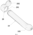
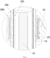
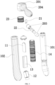
- Rod body 101. First plastic inner shell; 102. First silicone jacket; 103. First massage end; 11. First PCB board; 12. First massage module; 13. Power supply; 14. Wireless charging transmitter module; 20. Massage component; 201. Mounting ring; 202. Second massage end; 203. Second plastic inner shell; 204. Second silicone jacket; 21. Second PCB board; 22. Second massage module; 23. Wireless charging receiver module.
- a length-adjustable massager based on wireless induction power supply comprises a rod body 10 and a massage component 20 that can move back and forth along the lengthwise direction of the rod body 10;
- the rod body 10 is provided with a first PCB board 11, a first massage module 12, a power supply 13, and a wireless charging transmitter module 14;
- the first massage module 12, power supply 13, and wireless charging transmitter module 14 are electrically connected to the first PCB board 11;
- the massage component 20 is provided with a second PCB board 21, a second massage module 22, and a wireless charging receiver module 23, and the second massage module 22 and the wireless charging receiver module 23 are electrically connected to the second PCB board 21; Moreover, the wireless charging transmitter module 14 is adapted to the wireless charging receiver module 23.
- the wireless charging transmitter module 14 inside the rod body 10 transmits the electrical energy of the power supply 13 (usually a rechargeable battery) to the wireless charging receiver module 23 of the massage component 20 through wireless induction, and the wireless charging receiver module 23 supplies the electrical energy to the second PCB board 21 and the second massage module 22 after receiving the relevant electric energy, so that the second massage module 22 works;
- the setting of components such as wires or conductive sheets is omitted, and the problem of leakage caused by exposed wires or conductive sheets can also be avoided, giving a higher sense of safety;
- the massage component 20 can move back and forth on the rod body 10, thereby adjusting the distance from the front end of the rod body 10 to the massage component 20 to meet the massage needs of different users.
- the rod body 10 comprises a first plastic inner shell 101 and a first silicone jacket 102 encased on the outside of the first plastic inner shell 101, wherein the first plastic inner shell 101 has a first mounting chamber;
- the first mounting chamber extends along the lengthwise direction of the first plastic inner shell 101, and the first massage module 12 (provided with a first vibration motor), battery, and first PCB board 11 are set in sequence from front to back in the first mounting chamber;
- the first massage module 12 corresponds to the front end of the first mounting chamber (the rod body 10).
- a holding slot is provided between the first plastic inner shell 101 and the first silicone jacket 102, and the wireless charging transmitter module 14 (usually a wireless charging transmission coil) is set in the holding slot, so as to ensure a better sealing and waterproofing of the wireless charging transmitter module 14 while also allowing the wireless charging transmitter module 14 to be closer to the outer surface of the bar body 10, making its connection with the wireless charging receiver module 23 more stable;
- the first PCB board 11 is electrically connected with a charging port and an open/close button, and the charging port is preferably set at the rear end of the rod body 10.
- the rod body 10 is in a strip shape
- the massage component 20 has a mounting ring 201.
- the mounting ring 201 is sleeved on the rod body 10, and the mounting ring 201 can slide back and forth on the rod body 10;
- the wireless charging receiver module 23 is preferably set on the mounting ring 201.
- a rod body 10 is provided with several massage components 20 with different functions (such as a suction massage component 20, a vibration massage component 20, a tapping massage component 20, etc.).
- the front section of the rod body 10 can be set in a strip shape, so that the mounting ring 201 can slide out of the rod body 10 from the front end of the rod body 10;
- the rear section of the rod body 10 is set in a strip shape, and the mounting ring 201 can slide out of the rod body 10 from the rear end of the rod body 10;
- the front and rear sections of the rod body 10 are both set in a strip shape, and the mounting ring 201 can slide out the rod body 10 from the front end and back end of the rod body 10;
- the rear section of the rod body 10 in this embodiment is in a strip shape, and the front section of the rod body 10 extends diagonally with a first massage end 103.
- the massage component 20 extends diagonally forward on the mounting ring 201 with a second massage end 202, and the second massage module 22 corresponds to the second massage end 202 (the second massage module 22 has a second vibration motor, and the second vibration motor corresponds to the second massage end 202);
- the second massage component 20 has a second plastic inner shell 203 and a second silicone jacket 204 set on the outer side of the second plastic inner shell 203, and the second massage module 22 is set inside the second plastic inner shell 204.
- the outer surfaces of the first silicone jacket 102 and the second silicone jacket 204 are both provided with massage patterns.
- the design focus of the present invention is to set a wireless charging transmitter module on the rod body and a wireless charging receiver module adapted to it on the massage component, so that the rod body can supply power to the massage component, which solves the deficiency of the prior art that the massage component and the rod body need to be connected through wires or conductive sheets, making the product factor of safety higher and easier to be accepted by consumers; Furthermore, the massage component can move back and forth on the rod body, thereby adjusting the position of the massage component on the rod body to meet the needs of different consumers.
Landscapes
- Health & Medical Sciences (AREA)
- Animal Behavior & Ethology (AREA)
- Veterinary Medicine (AREA)
- Epidemiology (AREA)
- Pain & Pain Management (AREA)
- Physical Education & Sports Medicine (AREA)
- Rehabilitation Therapy (AREA)
- Public Health (AREA)
- General Health & Medical Sciences (AREA)
- Life Sciences & Earth Sciences (AREA)
- Engineering & Computer Science (AREA)
- Power Engineering (AREA)
- Reproductive Health (AREA)
- Computer Networks & Wireless Communication (AREA)
- Dermatology (AREA)
- Percussion Or Vibration Massage (AREA)
Applications Claiming Priority (1)
| Application Number | Priority Date | Filing Date | Title |
|---|---|---|---|
| CN202321522277 | 2023-06-15 |
Publications (3)
| Publication Number | Publication Date |
|---|---|
| EP4477203A1 true EP4477203A1 (fr) | 2024-12-18 |
| EP4477203B1 EP4477203B1 (fr) | 2025-06-04 |
| EP4477203C0 EP4477203C0 (fr) | 2025-06-04 |
Family
ID=87418772
Family Applications (1)
| Application Number | Title | Priority Date | Filing Date |
|---|---|---|---|
| EP23185981.0A Active EP4477203B1 (fr) | 2023-06-15 | 2023-07-18 | Masseur réglable en longueur basé sur une alimentation à induction sans fil |
Country Status (3)
| Country | Link |
|---|---|
| US (1) | US20240421635A1 (fr) |
| EP (1) | EP4477203B1 (fr) |
| JP (1) | JP3244041U (fr) |
Citations (3)
| Publication number | Priority date | Publication date | Assignee | Title |
|---|---|---|---|---|
| US20130261385A1 (en) * | 2012-03-14 | 2013-10-03 | Ralph Zipper | Sexual stimulation device using light therapy |
| US9737458B1 (en) * | 2017-03-21 | 2017-08-22 | Shenzhen Aigan Technology Co. Ltd. | Prostate massager |
| CN216598314U (zh) | 2022-01-24 | 2022-05-24 | 深圳欧拓奇科技有限公司 | 一种组合装置 |
-
2023
- 2023-07-18 EP EP23185981.0A patent/EP4477203B1/fr active Active
- 2023-07-18 US US18/353,929 patent/US20240421635A1/en active Pending
- 2023-08-08 JP JP2023002865U patent/JP3244041U/ja active Active
Patent Citations (3)
| Publication number | Priority date | Publication date | Assignee | Title |
|---|---|---|---|---|
| US20130261385A1 (en) * | 2012-03-14 | 2013-10-03 | Ralph Zipper | Sexual stimulation device using light therapy |
| US9737458B1 (en) * | 2017-03-21 | 2017-08-22 | Shenzhen Aigan Technology Co. Ltd. | Prostate massager |
| CN216598314U (zh) | 2022-01-24 | 2022-05-24 | 深圳欧拓奇科技有限公司 | 一种组合装置 |
Also Published As
| Publication number | Publication date |
|---|---|
| EP4477203B1 (fr) | 2025-06-04 |
| EP4477203C0 (fr) | 2025-06-04 |
| JP3244041U (ja) | 2023-10-05 |
| US20240421635A1 (en) | 2024-12-19 |
Similar Documents
| Publication | Publication Date | Title |
|---|---|---|
| US11283282B2 (en) | Multi-functional smart wireless charging device for cell phone in horizontal placement and vertical placement | |
| US10541484B2 (en) | Connector assembly with retractable probe contact recessed behind mating surface and stationary pad contact extending beyond mating surface | |
| CN201975560U (zh) | 一种改进型充电插座 | |
| WO2019007144A1 (fr) | Connecteur de charge/décharge magnétique | |
| EP4477203A1 (fr) | Masseur réglable en longueur basé sur une alimentation à induction sans fil | |
| CN208782518U (zh) | 一种多功能充电器 | |
| CN201204138Y (zh) | 一种大功率微动开关 | |
| RU2824539C1 (ru) | Регулируемый по длине массажер с беспроводным индукционным питанием | |
| CN207819495U (zh) | 一种iqos电子烟无线充电皮套 | |
| CN214707246U (zh) | 一种无线充闹钟 | |
| CN212542751U (zh) | 一种可承载大电流大功率实现快速充电的usb type a连接器 | |
| TWM576551U (zh) | Conductive connector for charging gun | |
| CN212726578U (zh) | 一种多功能蓝牙耳机充电装置 | |
| CN218071077U (zh) | 一种脖戴式多功能移动电源 | |
| CN203433423U (zh) | 一种多功能平板电脑保护套 | |
| CN114243338A (zh) | 一种旋转接触式高寿命光伏连接器母端子结构 | |
| CN210870200U (zh) | 一种蓝牙耳机充电盒 | |
| CN212626192U (zh) | 结构增强型充电连接器 | |
| CN217508324U (zh) | 一种磁吸无线充电支架 | |
| CN216702014U (zh) | 一种智慧式智能床头柜及床头柜组件 | |
| CN218997117U (zh) | 一种具有开关功能的5pinusb连接器 | |
| CN205195323U (zh) | 一种用于手机充电的结构 | |
| CN217158847U (zh) | 双壳抗干扰的usb母座连接器 | |
| CN217984000U (zh) | 一种具有多标准插头的充电器 | |
| CN220382367U (zh) | 一种设于翻盖连接器的充电装置 |
Legal Events
| Date | Code | Title | Description |
|---|---|---|---|
| PUAI | Public reference made under article 153(3) epc to a published international application that has entered the european phase |
Free format text: ORIGINAL CODE: 0009012 |
|
| STAA | Information on the status of an ep patent application or granted ep patent |
Free format text: STATUS: EXAMINATION IS IN PROGRESS |
|
| 17P | Request for examination filed |
Effective date: 20230718 |
|
| AK | Designated contracting states |
Kind code of ref document: A1 Designated state(s): AL AT BE BG CH CY CZ DE DK EE ES FI FR GB GR HR HU IE IS IT LI LT LU LV MC ME MK MT NL NO PL PT RO RS SE SI SK SM TR |
|
| GRAP | Despatch of communication of intention to grant a patent |
Free format text: ORIGINAL CODE: EPIDOSNIGR1 |
|
| STAA | Information on the status of an ep patent application or granted ep patent |
Free format text: STATUS: GRANT OF PATENT IS INTENDED |
|
| INTG | Intention to grant announced |
Effective date: 20250206 |
|
| GRAS | Grant fee paid |
Free format text: ORIGINAL CODE: EPIDOSNIGR3 |
|
| GRAA | (expected) grant |
Free format text: ORIGINAL CODE: 0009210 |
|
| STAA | Information on the status of an ep patent application or granted ep patent |
Free format text: STATUS: THE PATENT HAS BEEN GRANTED |
|
| AK | Designated contracting states |
Kind code of ref document: B1 Designated state(s): AL AT BE BG CH CY CZ DE DK EE ES FI FR GB GR HR HU IE IS IT LI LT LU LV MC ME MK MT NL NO PL PT RO RS SE SI SK SM TR |
|
| REG | Reference to a national code |
Ref country code: GB Ref legal event code: FG4D |
|
| REG | Reference to a national code |
Ref country code: CH Ref legal event code: EP |
|
| REG | Reference to a national code |
Ref country code: DE Ref legal event code: R096 Ref document number: 602023003803 Country of ref document: DE |
|
| REG | Reference to a national code |
Ref country code: IE Ref legal event code: FG4D |
|
| U01 | Request for unitary effect filed |
Effective date: 20250626 |
|
| U07 | Unitary effect registered |
Designated state(s): AT BE BG DE DK EE FI FR IT LT LU LV MT NL PT RO SE SI Effective date: 20250702 |
|
| U20 | Renewal fee for the european patent with unitary effect paid |
Year of fee payment: 3 Effective date: 20250714 |
|
| PG25 | Lapsed in a contracting state [announced via postgrant information from national office to epo] |
Ref country code: ES Free format text: LAPSE BECAUSE OF FAILURE TO SUBMIT A TRANSLATION OF THE DESCRIPTION OR TO PAY THE FEE WITHIN THE PRESCRIBED TIME-LIMIT Effective date: 20250604 |
|
| PG25 | Lapsed in a contracting state [announced via postgrant information from national office to epo] |
Ref country code: NO Free format text: LAPSE BECAUSE OF FAILURE TO SUBMIT A TRANSLATION OF THE DESCRIPTION OR TO PAY THE FEE WITHIN THE PRESCRIBED TIME-LIMIT Effective date: 20250904 Ref country code: GR Free format text: LAPSE BECAUSE OF FAILURE TO SUBMIT A TRANSLATION OF THE DESCRIPTION OR TO PAY THE FEE WITHIN THE PRESCRIBED TIME-LIMIT Effective date: 20250905 |
|
| PG25 | Lapsed in a contracting state [announced via postgrant information from national office to epo] |
Ref country code: PL Free format text: LAPSE BECAUSE OF FAILURE TO SUBMIT A TRANSLATION OF THE DESCRIPTION OR TO PAY THE FEE WITHIN THE PRESCRIBED TIME-LIMIT Effective date: 20250604 |
|
| PG25 | Lapsed in a contracting state [announced via postgrant information from national office to epo] |
Ref country code: HR Free format text: LAPSE BECAUSE OF FAILURE TO SUBMIT A TRANSLATION OF THE DESCRIPTION OR TO PAY THE FEE WITHIN THE PRESCRIBED TIME-LIMIT Effective date: 20250604 |
|
| PG25 | Lapsed in a contracting state [announced via postgrant information from national office to epo] |
Ref country code: RS Free format text: LAPSE BECAUSE OF FAILURE TO SUBMIT A TRANSLATION OF THE DESCRIPTION OR TO PAY THE FEE WITHIN THE PRESCRIBED TIME-LIMIT Effective date: 20250904 |
|
| PG25 | Lapsed in a contracting state [announced via postgrant information from national office to epo] |
Ref country code: IS Free format text: LAPSE BECAUSE OF FAILURE TO SUBMIT A TRANSLATION OF THE DESCRIPTION OR TO PAY THE FEE WITHIN THE PRESCRIBED TIME-LIMIT Effective date: 20251004 |
|
| PG25 | Lapsed in a contracting state [announced via postgrant information from national office to epo] |
Ref country code: SM Free format text: LAPSE BECAUSE OF FAILURE TO SUBMIT A TRANSLATION OF THE DESCRIPTION OR TO PAY THE FEE WITHIN THE PRESCRIBED TIME-LIMIT Effective date: 20250604 |
|
| PG25 | Lapsed in a contracting state [announced via postgrant information from national office to epo] |
Ref country code: CZ Free format text: LAPSE BECAUSE OF FAILURE TO SUBMIT A TRANSLATION OF THE DESCRIPTION OR TO PAY THE FEE WITHIN THE PRESCRIBED TIME-LIMIT Effective date: 20250604 |
|
| PG25 | Lapsed in a contracting state [announced via postgrant information from national office to epo] |
Ref country code: SK Free format text: LAPSE BECAUSE OF FAILURE TO SUBMIT A TRANSLATION OF THE DESCRIPTION OR TO PAY THE FEE WITHIN THE PRESCRIBED TIME-LIMIT Effective date: 20250604 |
|
| PG25 | Lapsed in a contracting state [announced via postgrant information from national office to epo] |
Ref country code: MC Free format text: LAPSE BECAUSE OF FAILURE TO SUBMIT A TRANSLATION OF THE DESCRIPTION OR TO PAY THE FEE WITHIN THE PRESCRIBED TIME-LIMIT Effective date: 20250604 |
|
| PLBE | No opposition filed within time limit |
Free format text: ORIGINAL CODE: 0009261 |
|
| STAA | Information on the status of an ep patent application or granted ep patent |
Free format text: STATUS: NO OPPOSITION FILED WITHIN TIME LIMIT |
|
| REG | Reference to a national code |
Ref country code: CH Ref legal event code: L10 Free format text: ST27 STATUS EVENT CODE: U-0-0-L10-L00 (AS PROVIDED BY THE NATIONAL OFFICE) Effective date: 20260416 |