EP4477275A1 - Seilgurt - Google Patents
Seilgurt Download PDFInfo
- Publication number
- EP4477275A1 EP4477275A1 EP24179002.1A EP24179002A EP4477275A1 EP 4477275 A1 EP4477275 A1 EP 4477275A1 EP 24179002 A EP24179002 A EP 24179002A EP 4477275 A1 EP4477275 A1 EP 4477275A1
- Authority
- EP
- European Patent Office
- Prior art keywords
- loop
- belt
- strap
- ring
- fold
- Prior art date
- Legal status (The legal status is an assumption and is not a legal conclusion. Google has not performed a legal analysis and makes no representation as to the accuracy of the status listed.)
- Granted
Links
Images


Classifications
-
- A—HUMAN NECESSITIES
- A62—LIFE-SAVING; FIRE-FIGHTING
- A62B—DEVICES, APPARATUS OR METHODS FOR LIFE-SAVING
- A62B35/00—Safety belts or body harnesses; Similar equipment for limiting displacement of the human body, especially in case of sudden changes of motion
- A62B35/0006—Harnesses; Accessories therefor
- A62B35/0025—Details and accessories
-
- A—HUMAN NECESSITIES
- A62—LIFE-SAVING; FIRE-FIGHTING
- A62B—DEVICES, APPARATUS OR METHODS FOR LIFE-SAVING
- A62B35/00—Safety belts or body harnesses; Similar equipment for limiting displacement of the human body, especially in case of sudden changes of motion
- A62B35/04—Safety belts or body harnesses; Similar equipment for limiting displacement of the human body, especially in case of sudden changes of motion incorporating energy absorbing means
-
- A—HUMAN NECESSITIES
- A62—LIFE-SAVING; FIRE-FIGHTING
- A62B—DEVICES, APPARATUS OR METHODS FOR LIFE-SAVING
- A62B35/00—Safety belts or body harnesses; Similar equipment for limiting displacement of the human body, especially in case of sudden changes of motion
- A62B35/0006—Harnesses; Accessories therefor
- A62B35/0018—Full body harnesses covering at least shoulders and thighs
Definitions
- the invention relates to a rope harness.
- the rope harness has several attachment points including an umbilical attachment point which is intended to be attached to an attachment point, for example an anchor point or a lifeline.
- the umbilical attachment point can be used to secure the shoulder straps in a removable manner, which makes it easier to install the harness on the user.
- using the same ring to secure the shoulder straps and to suspend the user by the belt degrades the ergonomics of the suspension point, which complicates the work of the rope access technician.
- the document EP2649618 discloses a roping harness having a belt with a back band extended by a belly band to close the belt.
- the belly band is movable relative to the back band to adjust the circumference of the harness.
- a central attachment ring is attached to the belly band by means of a strap that is sewn onto the belly band. The strap extends from the leg loops.
- the ring is arranged above the belly band.
- An object of the invention is to provide a rope harness whose ergonomics of the ventral suspension point and the connections to the leg loops are improved compared to the configurations of the prior art.
- the central portion extends predominantly in the longitudinal direction of the belt from the first fold to the second fold, the central portion being secured to the belt between the first fold and the second fold.
- At least one seam securely mounts together the ring, the central portion of the link strap and the belt, the ring surrounding the belt and the central portion of the link strap.
- the rope harness is remarkable in that the ring defines at least a first loop projecting from the belt away from the first and second leg loops.
- the leg loop link is attached to the belt beyond the ring on either side of the ring.
- the leg loop link is attached to the belt by belt stitching.
- the ring is formed by a first strap, a first end of which is attached to a second end by strength stitching.
- the strength stitching resists a first force applied between the first buckle and the thigh loops and the belt seams give way to said first effort.
- the leg loop link is made of a link strap which has a breaking strength in its direction which connects the first leg loop with the second leg loop which is lower than a breaking strength of the ring in a direction perpendicular to the longitudinal direction of the belt.
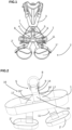
- FIGS. 1 and 2 illustrate a roping harness which comprises a belt 1 and a pair of leg loops 2 with a first leg loop 2' and a second leg loop 2".
- the roping harness also has shoulder straps 3, one end of which is preferably mounted so as to be removable relative to the belt 1.
- the rope harness also comprises a ventral suspension point 4 provided with a first loop 5 and a second loop 6.
- the first loop 5 is preferably intended to receive the attachment of the shoulder straps 3, for example a shoulder strap connector 7.
- the second loop 6 is preferably intended to connect to an anchor point, for example a lifeline.
- the second loop 6 is intended to receive a wire element, a suspension connector 8 or any other element allowing the suspension of the harness.
- the ventral suspension point 4 is also called the umbilical suspension point.
- the ventral suspension point 4 is capable of supporting a user installed in the harness and suspended by means of the harness.
- the ventral suspension point 4 is arranged in the midsagittal plane and is located near the user's navel.
- the belt 1 has a belt strap that extends in a longitudinal direction defining the circumference of the belt 1.
- the belt strap has a length greater than its width, itself greater than its thickness.
- the belt 1 has an inner face intended to be facing the user and preferably in contact with the latter and an opposite outer face.
- the ventral suspension point 4 has a first strap 9 attached to the belt 1, for example by a seam, in order to attach the ventral suspension point 4 to the belt 1.
- the first strap 9 forms a ring 10 around the belt 1. In other words, the belt 1 passes through the ring 10.
- the ventral suspension point 4 has a first loop 5 and a second loop 6 which are distinct.
- the first loop 5 and the second loop 6 are installed inside the ring 10.
- the first loop 5 being distinct from the second loop 6, an element installed in the first loop 5, for example a rope or a connector, cannot move to reach the second loop 6 and vice versa.
- the first loop 5 is outside the second loop 6 and the second loop 6 is outside the first loop 5.
- the arrangement of the two loops is different from the construction disclosed in the document EP2401038 which has an external loop arranged around an internal loop with two connectors which are arranged one above the other according to the rostro-caudal axis of the user.
- a connector arranged in the internal loop can only move within the space delimited by the external loop and a movement of the internal loop forward tends to move the other connector arranged in the other loop which can be detrimental.
- each leg loop 2 is connected by a leg loop link 11 which passes through the ring.
- each leg loop 2 is fixed to the belt 1 independently of the ring 10, for example by a specific seam.
- the straps from the leg loops form the umbilical suspension point.
- the straps are attached to the belt.
- the straps are wide and the seams are sized to withstand all fall forces.
- the dimensions of the straps imply a certain stiffness.
- the first loop 5 and the second loop 6 are arranged next to each other in a direction parallel to an axis which passes through the external face and the internal face of the belt 1.
- the first loop 5 is intended to be arranged between the second loop 6 and the user.
- the first loop 5 receives the connector 7 which makes the mechanical connection between the shoulder straps 3 and the belt 1.
- the connector 7 can be a removable connector.
- the second loop 6 can receive a connector 8 which is preferably a non-removable connector.
- the first loop 5 and the second loop 6 are mounted to be movable relative to each other in a direction which is parallel to a first direction which crosses the inner face and the outer face at the location of the attachment between the belt 1 and the ring 10.
- the first loop 5 and the second loop 6 are mounted protruding from the belt 1 in a direction that extends towards the shoulder straps 3, i.e. upwards when the user is standing. It is then possible to have a movement between the two loops and therefore between the two elements installed in the two loops, which improves the transfer of force to the belt 1.
- the movement of one loop relative to the other is in a direction that crosses the external face and the internal face of the belt 1.
- the ring 10 is fixed to the belt 1 so as to fix the position of the ventral suspension point 4 in the longitudinal direction of the belt 1 and prevent the ring 10 from rotating around the belt 1 in the longitudinal direction and perpendicular to the longitudinal direction.
- the fixing of the ring 10 to the belt 1 allows for better operation of the two buckles 5 and 6.
- the two loops 5 and 6 are formed by the single first strap 9, the two ends of which are fixed to each other to form the ring 10 and which is shaped to define the two loops 5 and 6.
- the first strap 9 and a second strap 12 are used to form the first loop 5 and the second loop 6.
- the first strap 9 forms a ring 10 which surrounds the belt 1.
- the second strap 12 is arranged in the ring 10 to divide the ring 10 into the first loop 5 and the second loop 6.
- the first strap 9 is distinct from the strap which forms the first thigh circumference 2' and distinct from the strap which forms the second thigh circumference 2". The same is true for the second strap 12.
- the second strap 12 is fixed to the first strap 9, preferably by sewing to define the two buckles.
- the second strap 12 separates the first loop 5 and the second loop 6. It is advantageous that the first strap 9 and the second strap 12 are attached to the belt 1.
- the second strap 12 is installed inside the ring 10 so as to separate two spaces which form the two loops 5 and 6.
- each loop has a first end fixed to the belt 1 in order to facilitate the absorption of force on the belt 1. More preferably, each loop has a second end fixed to the belt 1.
- Each of the loops is distinct so that an element arranged in the first loop 5 cannot move to the second loop 6 and vice versa.
- the first loop 5 and the second loop 6 are arranged protruding from the belt 1 towards the shoulder straps 3.
- the closure of the ring 10 by stitching connecting the two opposite ends of the first strap 9 is different from the stitching for attachment to the belt 1 so as to make the stitching which closes the ring 10 and the stitching which attaches the ring 10 to the belt 1 work differently.
- the two ends of the first strap 9 which are fixed together to close the ring 10 form all or part of the first loop 5 or the second loop 6 and more preferably at least part of the second loop 6. Doubling the thickness makes it possible to increase the rigidity of the loop to facilitate its handling.
- the overlap length between the two ends of the first strap 9 represents at least 30% of the length of the second loop 6, preferably the distance between the two attachment points to the belt 1. More preferably, the overlap length represents at least 50% of the length of the second loop 6, or even more than 70% of the length of the second loop 6.
- the second strap 12 forms the curved part of the second buckle 6, that is to say the part which is intended to receive the connector 7 of the shoulder straps 3.
- the second strap 12 prevents wear of the first strap 9.
- the second strap 12 has a single end fixed directly to the belt 1.
- fixed directly to the belt we mean a fixing where a part of the second strap 12 is fixedly mounted relative to a part of the belt 1.
- the second strap 12 can be in direct contact with the belt 1 or separated for example by the leg loop link 11.
- the fixing is preferably obtained by sewing, the sewing thread passes through the second strap 12, the belt 1 and it can pass through the leg loop link 11 and preferably the first strap 9.
- the overlapping area between the two ends of the first strap 9 has fasteners, for example strength seams 14, which extend continuously or quasi-continuously over the entire overlapping length to prevent the installation of a connector or a wire element between the two strands of the first strap 9 and thus prevent the formation of an additional loop.
- fasteners for example strength seams 14, which extend continuously or quasi-continuously over the entire overlapping length to prevent the installation of a connector or a wire element between the two strands of the first strap 9 and thus prevent the formation of an additional loop.
- the attachment between the belt 1 and the first strap 9 as well as the attachment between the belt 1 and the second strap 12 extends continuously or quasi-continuously to prevent the installation of a connector or a wire element between the belt 1 and each of the first strap 9 and the second strap 12 and thus prevent the formation of an additional loop.
- the attachment between the second strap 12 and the first strap 9, for example by means of first loop stitching 13, extends continuously or quasi-continuously to prevent the installation of a connector or wire element between the first strap 9 and the second strap 12 and thus prevent the formation of an additional loop.
- This construction is advantageous, because the connection of the various elements with the belt 1 is maintained by means of the ring 10. It is therefore possible to reduce the size of the ventral suspension point 4 by choosing a ring 10 whose mechanical performance is chosen to support a predefined set of forces. This makes it possible, for example, to choose the thickness, the width, the material as well as the configuration of the fasteners which close the ring 10 in the first strap 9.
- the first loop 5 receives the attachment of the straps 3 and the second loop 6 receives the attachment to the anchor point, for example a lifeline.
- the first loop 5 is at least partially covered by the second strap 12. More preferably, the attachment between the first strap 9 and the second strap 12 is obtained by sewing.
- the first loop seams 13 between the first strap 9 and the second strap 12 along the first loop 5 work to peel. It is advantageous to configure these first loop seams 13 to yield when subjected to a first threshold force which is equal to a maximum tolerated force from which the suspension point can no longer be used and which is less than a force causing the ring 10 to break.
- the first strap 9 is attached to the second strap 12 along the first loop 5 by first loop seams 13 and a first end of the first strap 9 is attached to a second end of the first strap 9 by resistance seams 14.
- the resistance seams 14 resist a first force applied between the second loop 6 and the belt 1 and the first loop seams 13 yield to said first force.
- the user detects that the harness is no longer usable.
- the sewing threads serve as indicators of the application of a force greater than the maximum authorized force.
- the first strap 9 is attached to the belt 1 by belt stitching 15 and a first end of the first strap 9 is attached to a second end of the first strap 9 by strength stitching 14.
- the strength stitching 14 resists a first force applied between the second loop 6 and the belt 1 and the belt stitching 15 yields to said first force.
- the same may apply when the belt seams 15 fix together the belt 1 and the first strap 9, or fix together the belt 1 and the second strap 12, or fix together, the belt 1, the first strap 9 and the second strap 12.
- the second strap 12 is arranged against the outer face of the belt 1, but a close operation can be obtained by placing the second strap 12 against the inner face of the belt 1 as illustrated in figure 5 .
- the arrangement of the second strap 12 on one side or the other of the belt 1 changes little the mechanical performance of the ventral suspension point 4.
- the attachment of the second strap 12 to the belt 1 ensures better absorption of forces by the belt 1 in comparison with a second strap 12 attached to the second buckle 6 to close the second buckle 6.
- the second strap 12 has a resistance to elongation which is lower than that of the fasteners. In the event of application of a significant force, the second strap 12 gives way in the separation zone between the first loop 5 and the second loop 6. The observation of the rupture of the second strap 12 is an indicator of a force greater than a threshold value.
- the second strap 12 is arranged in the second loop 6.
- the first loop 5 can be closed by a seam 13 to serve as an indicator that gives way when the suspension point is subjected to a significant force. It is also possible to have the second strap 12 break. However, this embodiment is less advantageous than that of the figures 4 And 5 because the control of the breaking forces of the indicators is more difficult to obtain.
- the second strap 12 can be arranged on one side or the other of the belt 1.
- FIGS 7 and 8 illustrate embodiments where the second strap 12 is used and where the second strap does not provide the separation between the two loops.
- This embodiment is less advantageous than the previous ones because the closure of the loops is achieved by at least one seam, preferably by a seam at the end of each loop.
- This embodiment is less interesting because the separation between the loops is less well controlled over time because the forces applied to the seams are significant.
- the first strap 9 forms a ring 10 which surrounds the belt 1.
- the leg loop link 11 passes through the ring 10. More preferably, the leg loop link 11 is fixed to the belt 1 with the same stitching as the first strap 9 and possibly as the second strap 12.
- the first loop 5 and the second loop 6 are arranged opposite each other in a direction which is perpendicular to the external face of the belt 1.
- the two loops pass through in the longitudinal direction of the belt 1.
- leg loop link 11 which connects the two leg loops 2 and which passes through the ring 10 is particularly advantageous because it makes it possible to ensure the mechanical connection between the leg loops 2 and the belt 1 while relaxing the technological constraints on the attachment between the leg loops 2 and the belt 1.
- the ventral suspension point 4 may have a first loop 5 and a second loop 6. However, alternatively, it is possible for the suspension point to have only the first loop 5 or only the second loop 6 as illustrated in figure 9 .
- the ventral suspension point 4 defines three loops with an additional loop which is arranged in the first loop 5.
- the additional loop is formed by the second strap 12 and preferentially uses the portion of the second strap 12 which separates the first loop 5 and the second loop 6.
- the connector 7 is installed in the first loop 5 outside the additional loop. More preferably, the connector 7 is removable from the first loop 5.
- the connector 7 forms the connection between the shoulder straps 3 and the belt 1.
- the second loop 6 is used to secure the harness to an anchor point.
- the straps forming the connections of the leg loops are fixed to the belt and they form the loop(s) which delimit the ventral suspension point. Consequently, the performance of the straps of the leg loops is chosen in order to withstand the mechanical constraints of a ventral suspension point.
- the link strap defines folds 16 with a first fold 16' between the central portion of the link strap and a first strand extending from the first leg loop.
- the link strap defines a second fold 16" between the central portion of the link strap and a second strand extending from the second leg loop.
- the first fold is separated from the second fold by the ring 10.
- the two strands attach to the belt 1 with a wider spacing than prior art configurations.
- the first fold and the second fold are fixedly mounted to the belt 1 by at least one seam.
- the central portion of the connecting strap is fixedly mounted to the belt 1 so that the belt 1 and the central portion deform in the same way in the longitudinal direction of the belt as well as in the transverse direction of the belt 1.
- the first fold 16' and the second fold 16" are separated by the ring in the longitudinal direction of the belt 1.
- first fold 16' and/or the second fold 16" are fixed to the belt 1 by fold seams 17.
- the ring 10 is formed by a first strap 9, a first end of which is fixed to a second end by resistance seams 14.
- the resistance seams 14 resist a first force applied between the first buckle 5 and the thigh loops 2 and the fold seams 17 yield to said first force.
- the leg loop link 11 is fixed to the belt 1 by belt stitching 15.
- the ring 10 is formed by a first strap 9, a first end of which is fixed to a second end by belt stitching 15. resistance 14.
- the resistance seams 14 resist a first force applied between the first buckle 5 and the thigh loops 2 and the belt seams 15 yield to said first force.
- the use of a belt seam 15 and/or a folding seam 17 that are less resistant than the resistance seam 14 makes it possible to have an indicator of a violent force on the harness.
- the first force may represent the maximum force authorized for the harness.
- the folding seam 17 and/or the belt seam 15 give way.
- the seams that have given way serve as an indicator.
- leg loop link 11 inside the ring 10 and the dissociation between the leg loop link 11 and the buckle intended to be fixed to the anchor point makes it possible to modify the mechanical behavior of the straps which form the connection between the leg loops 2 and the ventral suspension point 4.
- leg loop link 11 it is advantageous to use a strap that is less wide than the straps of the prior art, which improves the comfort of the leg loop connection.
- the leg loop link 11 extends mainly or exclusively in the longitudinal direction of the belt 1 and the leg loop link 11 is fixedly mounted to the belt 1.
- the leg loop link 11 and the belt 1 are deform in a similar manner, this allows for more uniform mechanical operation between the leg loop link 11 and the belt 1.
Landscapes
- Health & Medical Sciences (AREA)
- General Health & Medical Sciences (AREA)
- Business, Economics & Management (AREA)
- Emergency Management (AREA)
- Emergency Lowering Means (AREA)
- Details Of Garments (AREA)
- Package Frames And Binding Bands (AREA)
Applications Claiming Priority (1)
| Application Number | Priority Date | Filing Date | Title |
|---|---|---|---|
| FR2305950A FR3149796B1 (fr) | 2023-06-13 | 2023-06-13 | Harnais d’encordement |
Publications (2)
| Publication Number | Publication Date |
|---|---|
| EP4477275A1 true EP4477275A1 (de) | 2024-12-18 |
| EP4477275B1 EP4477275B1 (de) | 2026-01-21 |
Family
ID=88069061
Family Applications (1)
| Application Number | Title | Priority Date | Filing Date |
|---|---|---|---|
| EP24179002.1A Active EP4477275B1 (de) | 2023-06-13 | 2024-05-30 | Seilgurt |
Country Status (5)
| Country | Link |
|---|---|
| US (1) | US20240416159A1 (de) |
| EP (1) | EP4477275B1 (de) |
| JP (1) | JP2025000578A (de) |
| CN (1) | CN222885478U (de) |
| FR (1) | FR3149796B1 (de) |
Families Citing this family (3)
| Publication number | Priority date | Publication date | Assignee | Title |
|---|---|---|---|---|
| US20220040510A1 (en) * | 2020-08-05 | 2022-02-10 | Alexander Andrew, Inc. Dba Falltech | Web harness system with leg components |
| DE202021104371U1 (de) * | 2020-08-19 | 2021-10-18 | Cmc Rescue, Inc. | Umwandelbarer Gurt |
| JP7829555B2 (ja) * | 2020-08-26 | 2026-03-13 | スリーエム イノベイティブ プロパティズ カンパニー | 擬似交差腹部ストラップを有する安全ハーネス |
Citations (3)
| Publication number | Priority date | Publication date | Assignee | Title |
|---|---|---|---|---|
| FR2649618A1 (fr) * | 1989-07-17 | 1991-01-18 | Petzl Ets | Cuissard ou harnais d'encordement a ceinture ajustable |
| EP2401038A1 (de) | 2009-02-26 | 2012-01-04 | Camp S.p.A. | Element zum anbringen von teilen eines sicherheitsgurts |
| EP2649618A2 (de) | 2010-12-06 | 2013-10-16 | Intel Corporation | Befehle zur aktualisierung einer speichervorrichtung bei laufendem betrieb |
-
2023
- 2023-06-13 FR FR2305950A patent/FR3149796B1/fr active Active
-
2024
- 2024-05-30 EP EP24179002.1A patent/EP4477275B1/de active Active
- 2024-06-10 US US18/738,444 patent/US20240416159A1/en active Pending
- 2024-06-12 JP JP2024095358A patent/JP2025000578A/ja active Pending
- 2024-06-12 CN CN202421329772.5U patent/CN222885478U/zh active Active
Patent Citations (3)
| Publication number | Priority date | Publication date | Assignee | Title |
|---|---|---|---|---|
| FR2649618A1 (fr) * | 1989-07-17 | 1991-01-18 | Petzl Ets | Cuissard ou harnais d'encordement a ceinture ajustable |
| EP2401038A1 (de) | 2009-02-26 | 2012-01-04 | Camp S.p.A. | Element zum anbringen von teilen eines sicherheitsgurts |
| EP2649618A2 (de) | 2010-12-06 | 2013-10-16 | Intel Corporation | Befehle zur aktualisierung einer speichervorrichtung bei laufendem betrieb |
Also Published As
| Publication number | Publication date |
|---|---|
| FR3149796A1 (fr) | 2024-12-20 |
| JP2025000578A (ja) | 2025-01-07 |
| US20240416159A1 (en) | 2024-12-19 |
| CN222885478U (zh) | 2025-05-20 |
| FR3149796B1 (fr) | 2025-06-20 |
| EP4477275B1 (de) | 2026-01-21 |
Similar Documents
| Publication | Publication Date | Title |
|---|---|---|
| EP4477275A1 (de) | Seilgurt | |
| EP3466493B1 (de) | Gurtzeug | |
| EP3375494B1 (de) | Gurtzeug | |
| EP3228363A1 (de) | Gurtzeug | |
| EP3211267B1 (de) | Sicherungsleine mit einem verbesserten drehwirbel | |
| EP1195109A1 (de) | Befestigungselement für Rucksack | |
| FR3049869A1 (fr) | Harnais | |
| EP1849502B1 (de) | Gurt für Seilgeschirr mit einem hervorstehenden Werkzeugträger | |
| FR2978515A1 (fr) | Dispositif de blocage et de deblocage d'un element tubulaire longiligne | |
| EP4477274B1 (de) | Seilgurt | |
| EP3549640B1 (de) | Gurtzeug | |
| EP3507188B1 (de) | Kupplungssystem, mit einem benutzer starr verbundene ausrüstungsanordnung, kupplungssystem und kite-stange für kiteboarding | |
| FR3132229A1 (fr) | Harnais d’encordement à point de suspension ventral | |
| EP3721946B1 (de) | Gurtzeug mit kompakter einstellvorrichtung | |
| FR2819700A1 (fr) | Dispositif de portage pour sac a dos | |
| FR3112370A1 (fr) | Dispositif porte-materiel | |
| EP3476246B1 (de) | Brustgurt | |
| EP4066906A1 (de) | Vorrichtung zur befestigung an einen verankerungspunkt und verfahren zur anwendung einer solchen befestigungsvorrichtung | |
| EP4631578A1 (de) | Vorrichtung zum verstellen eines drahtelements und seilgurt mit einer solchen verstellvorrichtung | |
| EP4631577A1 (de) | Gurtzeug mit verstellvorrichtung | |
| EP4389243B1 (de) | Nockenverriegelungsvorrichtung, verfahren zur herstellung einer solchen vorrichtung und verfahren zum ersetzen eines drahtelements einer solchen vorrichtung | |
| EP4458425A1 (de) | Textilverbinder, kabelbaum mit einem solchen textilverbinder und herstellungsverfahren | |
| FR3144017A1 (fr) | Dispositif de blocage à came mobile et procédé de fixation d’un dispositif de blocage à came mobile à un élément filaire | |
| EP4667068A1 (de) | Aufhängevorrichtung mit einem befestigungsbereich zwischen zwei strängen, eine solche aufhängvorrichtung enthaltende halterung, und verfahren zur herstellung einer solchen aufhängevorrichtung | |
| FR2772339A1 (fr) | Dispositif de securite pour attacher une voilure de parachute a un harnais de parachutiste |
Legal Events
| Date | Code | Title | Description |
|---|---|---|---|
| PUAI | Public reference made under article 153(3) epc to a published international application that has entered the european phase |
Free format text: ORIGINAL CODE: 0009012 |
|
| STAA | Information on the status of an ep patent application or granted ep patent |
Free format text: STATUS: THE APPLICATION HAS BEEN PUBLISHED |
|
| AK | Designated contracting states |
Kind code of ref document: A1 Designated state(s): AL AT BE BG CH CY CZ DE DK EE ES FI FR GB GR HR HU IE IS IT LI LT LU LV MC ME MK MT NL NO PL PT RO RS SE SI SK SM TR |
|
| STAA | Information on the status of an ep patent application or granted ep patent |
Free format text: STATUS: REQUEST FOR EXAMINATION WAS MADE |
|
| 17P | Request for examination filed |
Effective date: 20250611 |
|
| GRAP | Despatch of communication of intention to grant a patent |
Free format text: ORIGINAL CODE: EPIDOSNIGR1 |
|
| STAA | Information on the status of an ep patent application or granted ep patent |
Free format text: STATUS: GRANT OF PATENT IS INTENDED |
|
| RIC1 | Information provided on ipc code assigned before grant |
Ipc: A62B 35/00 20060101AFI20250812BHEP |
|
| INTG | Intention to grant announced |
Effective date: 20250905 |
|
| GRAS | Grant fee paid |
Free format text: ORIGINAL CODE: EPIDOSNIGR3 |
|
| GRAA | (expected) grant |
Free format text: ORIGINAL CODE: 0009210 |
|
| STAA | Information on the status of an ep patent application or granted ep patent |
Free format text: STATUS: THE PATENT HAS BEEN GRANTED |
|
| AK | Designated contracting states |
Kind code of ref document: B1 Designated state(s): AL AT BE BG CH CY CZ DE DK EE ES FI FR GB GR HR HU IE IS IT LI LT LU LV MC ME MK MT NL NO PL PT RO RS SE SI SK SM TR |
|
| REG | Reference to a national code |
Ref country code: CH Ref legal event code: F10 Free format text: ST27 STATUS EVENT CODE: U-0-0-F10-F00 (AS PROVIDED BY THE NATIONAL OFFICE) Effective date: 20260121 |
|
| REG | Reference to a national code |
Ref country code: DE Ref legal event code: R096 Ref document number: 602024002149 Country of ref document: DE |
|
| REG | Reference to a national code |
Ref country code: IE Ref legal event code: FG4D Free format text: LANGUAGE OF EP DOCUMENT: FRENCH |