EP4477402A1 - Dispositif et procédé de détection de corps étrangers dans un tapis diffusé - Google Patents
Dispositif et procédé de détection de corps étrangers dans un tapis diffusé Download PDFInfo
- Publication number
- EP4477402A1 EP4477402A1 EP24000072.9A EP24000072A EP4477402A1 EP 4477402 A1 EP4477402 A1 EP 4477402A1 EP 24000072 A EP24000072 A EP 24000072A EP 4477402 A1 EP4477402 A1 EP 4477402A1
- Authority
- EP
- European Patent Office
- Prior art keywords
- sensor
- sensor device
- mat
- foreign body
- evaluation
- Prior art date
- Legal status (The legal status is an assumption and is not a legal conclusion. Google has not performed a legal analysis and makes no representation as to the accuracy of the status listed.)
- Pending
Links
Images


Classifications
-
- B—PERFORMING OPERATIONS; TRANSPORTING
- B30—PRESSES
- B30B—PRESSES IN GENERAL
- B30B15/00—Details of, or accessories for, presses; Auxiliary measures in connection with pressing
- B30B15/26—Program-control arrangements
-
- B—PERFORMING OPERATIONS; TRANSPORTING
- B27—WORKING OR PRESERVING WOOD OR SIMILAR MATERIAL; NAILING OR STAPLING MACHINES IN GENERAL
- B27N—MANUFACTURE BY DRY PROCESSES OF ARTICLES, WITH OR WITHOUT ORGANIC BINDING AGENTS, MADE FROM PARTICLES OR FIBRES CONSISTING OF WOOD OR OTHER LIGNOCELLULOSIC OR LIKE ORGANIC MATERIAL
- B27N3/00—Manufacture of substantially flat articles, e.g. boards, from particles or fibres
- B27N3/08—Moulding or pressing
- B27N3/18—Auxiliary operations, e.g. preheating, humidifying, cutting-off
-
- G—PHYSICS
- G01—MEASURING; TESTING
- G01V—GEOPHYSICS; GRAVITATIONAL MEASUREMENTS; DETECTING MASSES OR OBJECTS; TAGS
- G01V3/00—Electric or magnetic prospecting or detecting; Measuring magnetic field characteristics of the earth, e.g. declination, deviation
- G01V3/08—Electric or magnetic prospecting or detecting; Measuring magnetic field characteristics of the earth, e.g. declination, deviation operating with magnetic or electric fields produced or modified by objects or geological structures or by detecting devices
-
- B—PERFORMING OPERATIONS; TRANSPORTING
- B07—SEPARATING SOLIDS FROM SOLIDS; SORTING
- B07C—POSTAL SORTING; SORTING INDIVIDUAL ARTICLES, OR BULK MATERIAL FIT TO BE SORTED PIECE-MEAL, e.g. BY PICKING
- B07C5/00—Sorting according to a characteristic or feature of the articles or material being sorted, e.g. by control effected by devices which detect or measure such characteristic or feature; Sorting by manually actuated devices, e.g. switches
- B07C5/34—Sorting according to other particular properties
- B07C5/3416—Sorting according to other particular properties according to radiation transmissivity, e.g. for light, x-rays, particle radiation
-
- B—PERFORMING OPERATIONS; TRANSPORTING
- B27—WORKING OR PRESERVING WOOD OR SIMILAR MATERIAL; NAILING OR STAPLING MACHINES IN GENERAL
- B27N—MANUFACTURE BY DRY PROCESSES OF ARTICLES, WITH OR WITHOUT ORGANIC BINDING AGENTS, MADE FROM PARTICLES OR FIBRES CONSISTING OF WOOD OR OTHER LIGNOCELLULOSIC OR LIKE ORGANIC MATERIAL
- B27N3/00—Manufacture of substantially flat articles, e.g. boards, from particles or fibres
- B27N3/08—Moulding or pressing
- B27N3/16—Transporting the material from mat moulding stations to presses; Apparatus specially adapted for transporting the material or component parts therefor, e.g. cauls
-
- B—PERFORMING OPERATIONS; TRANSPORTING
- B30—PRESSES
- B30B—PRESSES IN GENERAL
- B30B5/00—Presses characterised by the use of pressing means other than those mentioned in the preceding groups
- B30B5/04—Presses characterised by the use of pressing means other than those mentioned in the preceding groups wherein the pressing means is in the form of an endless band
- B30B5/06—Presses characterised by the use of pressing means other than those mentioned in the preceding groups wherein the pressing means is in the form of an endless band co-operating with another endless band
-
- G—PHYSICS
- G01—MEASURING; TESTING
- G01B—MEASURING LENGTH, THICKNESS OR SIMILAR LINEAR DIMENSIONS; MEASURING ANGLES; MEASURING AREAS; MEASURING IRREGULARITIES OF SURFACES OR CONTOURS
- G01B15/00—Measuring arrangements characterised by the use of electromagnetic waves or particle radiation, e.g. by the use of microwaves, X-rays, gamma rays or electrons
-
- G—PHYSICS
- G01—MEASURING; TESTING
- G01N—INVESTIGATING OR ANALYSING MATERIALS BY DETERMINING THEIR CHEMICAL OR PHYSICAL PROPERTIES
- G01N23/00—Investigating or analysing materials by the use of wave or particle radiation, e.g. X-rays or neutrons, not covered by groups G01N3/00 – G01N17/00, G01N21/00 or G01N22/00
- G01N23/02—Investigating or analysing materials by the use of wave or particle radiation, e.g. X-rays or neutrons, not covered by groups G01N3/00 – G01N17/00, G01N21/00 or G01N22/00 by transmitting the radiation through the material
- G01N23/06—Investigating or analysing materials by the use of wave or particle radiation, e.g. X-rays or neutrons, not covered by groups G01N3/00 – G01N17/00, G01N21/00 or G01N22/00 by transmitting the radiation through the material and measuring the absorption
- G01N23/16—Investigating or analysing materials by the use of wave or particle radiation, e.g. X-rays or neutrons, not covered by groups G01N3/00 – G01N17/00, G01N21/00 or G01N22/00 by transmitting the radiation through the material and measuring the absorption the material being a moving sheet or film
-
- G—PHYSICS
- G01—MEASURING; TESTING
- G01N—INVESTIGATING OR ANALYSING MATERIALS BY DETERMINING THEIR CHEMICAL OR PHYSICAL PROPERTIES
- G01N33/00—Investigating or analysing materials by specific methods not covered by groups G01N1/00 - G01N31/00
- G01N33/0004—Gaseous mixtures, e.g. polluted air
- G01N33/0009—General constructional details of gas analysers, e.g. portable test equipment
- G01N33/0011—Sample conditioning
- G01N33/0021—Sample conditioning involving the use of a carrier gas for transport to the sensor
-
- G—PHYSICS
- G01—MEASURING; TESTING
- G01V—GEOPHYSICS; GRAVITATIONAL MEASUREMENTS; DETECTING MASSES OR OBJECTS; TAGS
- G01V9/00—Prospecting or detecting by methods not provided for in groups G01V1/00 - G01V8/00
-
- G—PHYSICS
- G01—MEASURING; TESTING
- G01N—INVESTIGATING OR ANALYSING MATERIALS BY DETERMINING THEIR CHEMICAL OR PHYSICAL PROPERTIES
- G01N2223/00—Investigating materials by wave or particle radiation
- G01N2223/60—Specific applications or type of materials
- G01N2223/619—Specific applications or type of materials wood
-
- G—PHYSICS
- G01—MEASURING; TESTING
- G01N—INVESTIGATING OR ANALYSING MATERIALS BY DETERMINING THEIR CHEMICAL OR PHYSICAL PROPERTIES
- G01N2223/00—Investigating materials by wave or particle radiation
- G01N2223/60—Specific applications or type of materials
- G01N2223/652—Specific applications or type of materials impurities, foreign matter, trace amounts
-
- G—PHYSICS
- G01—MEASURING; TESTING
- G01N—INVESTIGATING OR ANALYSING MATERIALS BY DETERMINING THEIR CHEMICAL OR PHYSICAL PROPERTIES
- G01N33/00—Investigating or analysing materials by specific methods not covered by groups G01N1/00 - G01N31/00
- G01N33/46—Wood
Definitions
- the invention relates to a device for detecting foreign bodies in a mat scattered on a conveyor device during the production of material plates, wherein the mat consists at least partially of fibers or chips and binding agents which are pressed together while increasing the temperature, and wherein at least one first sensor device is provided which operates with electromagnetic or ultrasonic waves or with magnetic fields or with radiometry and is directed at one or more spatial measuring areas of the mat in order to detect foreign bodies.
- the invention also relates to a method for detecting foreign bodies in a mat scattered on a conveyor device during the production of material plates, wherein the mat consists at least partially of fibers or chips and binding agents which are pressed together while increasing the temperature, wherein at least one first sensor device operating with electromagnetic or ultrasonic waves or with magnetic fields or with radiometry is used, which is directed at one or more spatial measuring areas of the mat in order to detect foreign bodies.
- the invention further relates to a production plant for producing material panels with a scattering station for scattering a mat onto a conveyor device, the mat consisting at least partially of fibers or chips and binding agents, and a press for compacting the mat, which comprises the device according to the invention for detecting foreign bodies, as well as a manufacturing method for material panels with a scattering station in which a mat is scattered onto a conveyor device, the mat consisting at least partially of fibers or chips and binding agents and is compacted in a press that uses the method according to the invention for detecting foreign bodies.
- Material boards are primarily understood to mean wood-based panels that are already produced in a preferably continuous press.
- suitable materials are chipboard, MDF or OSB boards, whereby the particles containing the mat are then essentially wood fibers or wood chips that have been provided with a binding agent.
- other lignocellulosic materials such as the fibers of annual plants (e.g. from rice straw), have also been used to press material boards.
- material boards within the meaning of the invention can also be insulation boards, plasterboard, plastic boards or other material boards whose particles have been pressed by means of rotating belts in a continuous press with the application of heat. Such a press is marketed by the applicant under the name ContiRoll. Binding agents are usually added to the particles before the continuous press so that the material boards have a high level of stability.
- the fibers or chips are scattered in a scattering station onto a conveyor, usually a conveyor belt, also called a forming belt, where they form a mat that is conveyed towards the press.
- a conveyor belt also called a forming belt
- hydraulic components apply high pressure via mostly heatable pressure plates and rollers to the upper and/or lower steel press belt. between which the mat is compacted at the same feed rate as the press belts.
- These press belts are usually only 0.5 to 4 mm thick and very sensitive to excessive point pressures. A dent or damage that is too large can be the reason why only scrap is produced on the entire system. Changing the press belts is costly and labor-intensive and understandably undesirable.
- Typical compaction values in kg/m 3 are at product density after scattering density according to press MDF 18 - 35 600 - 900 chip 140 - 150 550 - 750 OSB 60 - 70 500 - 700
- the thickness of the mat to the material board is reduced so much that even small trapped foreign bodies can easily penetrate the surface.
- chips or fibers are subjected to various processes, such as being crushed, washed or sprayed with binding agents, before being stored in large bunkers in front of or above the spreading station.
- the many upstream processes result in unwanted foreign bodies becoming incorporated into the spreading process and remaining in the mat. Depending on the size and hardness of the foreign body, these can emerge from the surface during the compaction process of the press and cause damage to the press belts.
- metal detectors work inductively with a transmitter coil through which an alternating current flows, which creates an alternating magnetic field. If this alternating field passes through a conductive material lying beneath the probe, eddy currents are induced there, which in turn create a measurable magnetic field.
- Metal parts pose the greatest risk due to their density and metal detectors are relatively inexpensive. The detector can detect individual metal parts accurately enough. However, non-ferrous metals such as copper or aluminum are not included.
- a metal detector integrates the metal mass in its field area and cannot distinguish between a single large body and many small ones. This means that the metal detector will also detect a harmless area of metal dust as a foreign metal body and thus unnecessarily interrupt production.
- the metal detector cannot locate larger clumps of glue or, for example, a plastic nut, which are also harmful.
- An X-ray-based sensor device with the appropriate surface resolution can also detect the silhouette of a body with correspondingly higher densities.
- the scanner cannot detect the height and thus the volume and mass of the body. This means that not only metallic foreign bodies can be detected, but also those made of other materials with correspondingly high densities.
- the foreign body scanner can only detect the surface of the foreign body, a body that is flat enough to be harmless to the press belt would result in the foreign body ejection device being triggered incorrectly.
- the object is achieved in terms of the device with the features of claim 1 and in particular in that at least one second sensor device is provided multimodally, which is also aligned with the measuring areas, and wherein the first sensor device is suitable for detecting the material of the foreign body, and the second Sensor device is suitable for determining at least one foreign body dimension.
- the object is achieved in terms of the method with the features of claim 13 and in particular in that at least one second sensor device is used multimodally, which is also aligned with the measuring areas, possibly with a time delay, wherein the first sensor device is used to detect the material of the foreign body and the second sensor device is used to determine at least one foreign body dimension.
- a harmful foreign body can be identified much better than before.
- first and second sensor device There may be systems in which the first sensor device is used first and then the second sensor device for detection in the direction of travel of the mat. In other systems, the reverse order may be more useful. This depends on the material being scattered and the thickness or density of the mat. In one case, it may be preferable to first determine the material and then the dimensions of the foreign body, in another case it may be more useful to first determine the dimensions of the foreign body and then the material.
- first and second therefore simply state that there are two different sensor devices that can follow one another in any order.
- measuring range refers to the flat or spatially limited areas that the respective sensor device can detect. Such a measuring range can extend over the entire mat width and/or thickness.
- the first sensor device has a sensor to detect the metal content of a foreign body.
- a sensor for example a detector supported by electromagnetic coils, i.e. inductively, one immediately knows when a ferrous metal part is in the mat.
- the danger of the foreign body for the press belt can be determined.
- the operator of the production plant knows immediately that he does not have to interrupt the production of material plates if the metal detector has gone off, but the second sensor device gives the signal that it is only scattered tiny metal particles.
- Claims 4 to 7 specify particularly useful sensor devices. These sensor devices are already used in other technical areas, for example medicine or food technology, and have proven themselves.
- the first sensor is equipped with or connected to a detection unit for measuring a phase shift of the signal generated by a detected metal particle, in order to also enable identification of the type of metal in this way and thus to be able to distinguish between ferrous and non-ferrous metals.
- identification of the type of metal is possible in this way.
- a distinction can be made between copper, brass, aluminum, iron and steel, and based on the densities, even within the types into different types or categories, for example between cast iron or structural steel.
- the sensor fusion algorithm ically combines the measurement results of at least one first sensor device and at least one second sensor device and thus creates a complete and precise assessment of the condition of the foreign body. It then comes to the conclusion, for example based on a predefined harmfulness matrix, whether the foreign body is harmful to the press belt or not.
- the matrix provides a clear classification depending on the foreign body material and foreign body dimensions, for example.
- Dependency algorithms can also be stored with formulas that define a critical condition of the foreign body when a calculated limit value is exceeded.
- a foreign body ejection device in the event of an estimated possible harmfulness to the press belt, i.e. depending on the result of the sensor fusion in the evaluation device, a foreign body ejection device can be activated.
- the opening of a discharge chute or the activation of a suction device by this inventive device for detecting foreign bodies therefore takes place completely automatically.
- the operator of the production plant can also be sure that production will only be interrupted if a foreign body that could potentially damage the press belt is detected or if there is at least a high probability of such damage.
- the evaluation device if a large but very flat foreign body is hidden in the mat, which would already cause a production stop with a conventional foreign body scanner, it would be possible to let the production plant continue to run and, if necessary, to cut out the area with the foreign body from the material plate that is later produced. The production plant therefore does not have to be stopped for foreign bodies that have been detected but are harmless to the press belt.
- the trend with material panels is to be able to produce thinner and lighter panels. These are particularly affected by the problem and the device according to the invention is particularly suitable for mat thicknesses ⁇ 8 mm. It is therefore advantageous if, in addition to the at least one first sensor device and the at least one second sensor device, a thickness, density or basis weight measuring device is available for the mat.
- Such thickness, density or basis weight measuring devices are common in the production of scattered mats that are pressed into material panels and are known to experts. However, they are usually only used to measure the uniformity across the scattering height and/or across the width and along the conveyor belt.
- the thickness, density or basis weight measurement determined can also be transmitted to the evaluation unit. This measurement value can be taken into account in the evaluation matrix for the foreign body material and foreign body dimensions. With thin mats, even small foreign bodies can endanger the press belt.
- a path/time detection device is provided for synchronizing the sensor signals of the at least one first sensor device and the at least one second sensor device.
- the at least one first sensor device and the at least one second sensor device are arranged a little way apart from each other along the transport path of the mat, it must be ensured that the measured values of the first sensor device and the measured values of the second sensor device from the same measuring point are assigned to each other. Therefore, the measured values of the measuring point arranged downstream in the transport direction only arrive at the evaluation device later, depending on the transport speed of the mat. This time offset must be taken into account.
- the distance/time recording device it is possible to record this time difference and pass it on to the evaluation unit. In many cases the distance of the sensor device is fixed so that the distance/time recording device only transmits the speed of the conveyor device, for example the conveyor belt. The evaluation device can then calculate the time offset of the measurement signals and take this into account when analyzing the foreign bodies.
- the at least one first sensor device and the at least one second sensor device simultaneously detect the same measuring point on or in the mat. In this case, they could even be accommodated in one housing.
- the evaluation device can be designed to carry out a damage analysis.
- the device has at least one first sensor device which is directed at one or more spatial measurement areas of the mat in order to detect foreign bodies and at least one second sensor device which is also directed at the measurement areas, and wherein the first sensor device is suitable for carrying out a material detection of the foreign body and the second sensor device is suitable for determining at least one foreign body dimension
- an embodiment of the evaluation device in such a way that a damage analysis can be carried out results in the possibility that data which can be obtained and in particular obtained from a sensor fusion can be made available and in particular are made available as evidence of a damage analysis to be carried out. Overall, this results in the advantage that a good level of informativeness of the damage assessment can be achieved, which is already very useful in practice in many cases.
- the damage analysis can be designed to assign pulsating patterns of foreign bodies and to group them according to different edge shapes, for example. Even if the foreign bodies detected are made of the same material and are roughly the same size, they can be assigned to a different (sub)group within the damage analysis unit, from which a different group of possible causes of damage can be concluded.
- the damage analysis (unit) is therefore preferably also designed to form groups and/or matrixes.
- the device is developed in such a way that the evaluation device is designed to predict damage.
- Analogous training courses can also be used to work together with a damage prediction unit, which can predict damage from the data obtained to a certain degree of accuracy.
- a damage prediction unit which can predict damage from the data obtained to a certain degree of accuracy.
- special synergies also arise here if the evaluation device is equipped with both a damage analysis (unit) and a damage prediction (unit) or is in combination with them. There is an effective connection and the two analyses or analysis units are also networked with each other.
- the evaluation device can then recognize a damage pattern from the signals (data) obtained from the at least two sensors and, in particular, assign it with a particularly high degree of information to a specific device (station) in a system for producing material plates and predict when the damage will have reached a certain level in the future.
- the operator of such a system can then, for example, set a point at which the system will be shut down for maintenance in order to avoid a much more costly crash.
- the operator can then also decide - informed in good time - whether to have a detected component causing wear replaced early on within a planned maintenance measure.
- the evaluation device comprises a learning unit or is in operative connection with a learning unit.
- the plant has to be operated for many years, usually for at least two to three decades, often even longer.
- the plant must also be designed in such a way that the operator can produce other types of material board, e.g. chipboard, within one type of material board, e.g. thin boards, medium-thick boards, thick boards in single or multi-layer versions, or even produce different types of material board, e.g. chipboard, hybrid boards such as chipboard with MDF cover layers or similar.
- the learning unit can then help to transfer knowledge gained from the manufacturing process of one type of material to another type of material or even to the manufacturing process of another type of material board, especially within one and the same plant.
- the detectable foreign bodies and foreign body patterns do not necessarily have to come from the plant, or a facility and/or station in the plant, but can also be generated from the manufacturing process, especially if they are clumps or if foreign body particles were present in a raw material. This can be the case in particular when processing recycled material.
- annual plants, especially grass-like plants often have high silicate contents.
- the learning unit for identification at least possible damage patterns based on patterns of detected signals from the individual sensors.
- the learning unit can assign pulsating patterns to circulating processes or units, and the length of the cycle can then be determined based on the repetition interval. If different circulating belts (e.g. made of steel) are used in a process or in a system designed to carry out a procedure, for example a system for the production of material plates, the repetition interval can be used to limit or assign the damaged unit (station).
- different circulating belts e.g. made of steel
- Different raw materials may also tend to form different damage patterns and, if the learning unit is trained accordingly, can be used as indicative evidence.
- the device is operatively connected to at least one sensor assigned to a device/station of a production plant for the manufacture of material plates.
- the evaluation unit can compare foreign bodies detected by the at least two sensors and in particular patterns of foreign bodies that arise over a certain period of time with signals from the causing and/or processing units (stations) of a (production) plant for the manufacture of material plates. It is particularly valuable if the evaluation unit is also designed for sensor fusion with at least one further sensor, in particular at least one sensor assigned to a device/station of a production plant for the manufacture of material plates.
- the method claims essentially correspond to the device claims for detecting foreign bodies in a mat scattered on a conveyor device.
- Claims 22 and 23 state that it is advantageous to use both the device according to the invention and the analogous and corresponding method according to the invention for detecting foreign bodies in a production plant between the spreading station and the continuous presses.
- FIG. 1 A schematic section of a plant 1 for the production of a material plate is shown.
- a spreading station 3 On the left side, the end of a spreading station 3 is indicated, with which chips or fibers that are wetted with binding agents are spread onto a long conveyor device 4, in this embodiment a conveyor belt running over a support structure 17, to form a mat 5.
- the mat 5 can have several different layers with chips or fibers of different sizes, which are also scattered in different directions if necessary. In the Fig. 1 For reasons of clarity, only a short section of mat 5 is shown schematically.
- a continuous press 2 On the right edge, i.e. at the end of the conveyor line, there is the inlet to a continuous press 2. It has an upper press belt 18a and a lower press belt 18b, which run endlessly around various deflection rollers 16 and can apply pressure to the mat 5 from both sides.
- the Press belts 18a, 18b are thin metal belts which, when subjected to point pressure from sharp or hard foreign bodies, can be damaged to such an extent that the damage is transferred to the pressed mat 5 and is visible on the material plate when it exits the press 2 (not shown).
- the foreign body ejection device 11 is a type of chute that can be opened by pulling back a cover and/or a movable conveyor belt section 12 via adjustment motors 20. After removing the mat section that contains a foreign body 10 that potentially endangers the press belts 18a, 18b, the mat 5 no longer has a straight edge. Therefore, the system 1 for producing a material plate has a diagonal saw 9 that can saw a new straight edge into the mat 5 at a right angle to the feed direction. This edge can easily enter the continuous press 2.
- the decisive factor is that a first sensor device 6 and a second sensor device 7 are used.
- the first sensor device 6 is suitable for detecting the material of the foreign body
- the second sensor device 7 is suitable for determining the foreign body dimensions.
- the sensor device 7 is pre-designed for the sensor device 6.
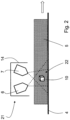
- the two sensor devices 6, 7 work in the reverse order, as is also shown purely schematically in Figure 2 is indicated.
- the physical measuring system of the sensor device 7 is equipped in such a way that it is able to measure dimensions of a foreign body. determine, if necessary even three-dimensionally.
- it can be, for example, a sensor device (7) acting with X-rays.
- This sensor device 6 can determine the material of the foreign body 10 or at least its density, so that a statement can be made from the dimensions and the material characteristics as to whether the foreign body 10 is harmful to the press belts 18a, 18b in the continuous press 2.
- an evaluation device 15 which has signal lines S1 to S5. It receives measured values from the first sensor device 6 via the signal line S1. It receives measured values from the second sensor device 7 via the signal line S2. Since the foreign body limit values stored in the evaluation device 15 are highly dependent on the mat thickness or density currently being used, corresponding data are supplemented via a signal line S3 from an additionally installed thickness, density or basis weight measuring device 8. In order to be able to take the time interval of a measuring range 22 from the second sensor device 7 to the first sensor device 6 into account in the measurements, the evaluation device 15 is also informed by a conveyor belt speed meter 19 with signal line S4 via a path/time recording device 13.
- the evaluation unit 15 detects a foreign body threatening the press belts 18a and 18b of the continuous press 2, it activates the foreign body ejection device 11.
- Fig. 2 The two sensor devices 6, 7 are arranged in the reverse order as in Fig. 1 However, the two sensor devices 6, 7 are in a housing 14 and are therefore arranged so close to each other that the measuring ranges 22 of the sensor devices 6, 7 overlap at least partially and both can carry out their measurements simultaneously.
- the inventions should also include other measuring methods of the sensor devices 6, 7. These include sensor devices that work with electromagnetic or ultrasonic waves or with magnetic fields or with radiometry.
- Figure 3 shows another embodiment.
- the same components and elements as in Figure 1 and 2 also have the same reference numerals.
- the embodiments shown in the figures are examples and are interchangeable within the scope of the disclosure.
- Figure 3 shows an embodiment of a system 1 for producing a material plate in a largely highly schematic form.
- Most of the devices/stations are shown only as small boxes, whereby the shape and size of the boxes are not representative of the allocation of a relation of the respective actual space requirement of the individual device/station in relation to another device/station.
- In the central area of the figure in a circular area formed by dashed lines, important features relating to the invention are shown in a highlighted but also schematic representation.
- the evaluation device 15 is designed for a damage analysis SA.
- the device 21 has at least one first sensor device 6 which is directed to one or more spatial measuring areas 22 of the mat 5 in order to detect foreign bodies 10 and has at least one second sensor device 7 which is also aligned with the measuring areas 22, and wherein the first sensor device 6 is suitable for detecting the material of the foreign body 10 and the second sensor device 7 is suitable for determining at least one foreign body dimension
- an embodiment of the evaluation device 15 such that a damage analysis SA can be carried out results in the possibility that data which can be obtained and in particular obtained from a sensor fusion can be and in particular are provided as indications of a damage analysis SA to be carried out.
- the sensor system of the evaluation device 15 provides the recognized shape with sufficient resolution to allow an edge view of the shape of the foreign body to be observed, which allows further conclusions to be drawn about possible damage patterns SB within the damage analysis SA, in particular within the device(s) 24, 25, 26, 27, 28, 3, 4 and/or system(s) 1 used for production.
- the first sensor 6 has a detection unit 6a for measuring a phase shift of the signal generated by a detected metal particle or is connected to it as shown, in order to also enable identification I of the type of metal in this way, and thus to be able to distinguish between ferrous and non-ferrous metals.
- the sensor 6, with the detection unit 6a can distinguish between copper, brass, aluminum, iron and steel, and based on the densities even within the types into different types or categories, for example between cast iron or structural steel.
- patterns M can be processed in the spatial and/or temporal distribution of the recording within the damage analysis SA of the evaluation device 15 in order to increase the degree of informative value.
- the damage analysis SA is, for example, such that designed to assign pulsating patterns M of foreign bodies 10 and, for example, to group them according to different edge shapes, even if the foreign bodies 10 detected are made of the same material and have approximately the same size, they can therefore be assigned to a different (sub)group within the damage analysis unit SA, from which a different group of possible causes of damage can be inferred.
- the damage analysis (unit) SA is therefore also designed to form groups and/or matrixes.
- the evaluation device 15 is also designed (at least optionally) for damage prediction SV, whereby the two analyses SA, SV or analysis units SA, SV are also networked with one another.
- the evaluation device 15 to recognize a damage pattern SB from the signals (data) S1, S2 obtained via the at least two sensors 6, 7 and, in particular, to assign it with a particularly high degree of information to a special device (station) 24, 25, 26, 27, 28, 3, 4 of a system 1 for producing material plates and to predict when the damage will have reached a certain level in the future.
- the operator of such a system 1 can then, for example, set a level at which the system 1 will be shut down for maintenance in order to avoid a significantly more costly crash.
- the operator can then also decide - informed in good time - whether to have a component causing detected wear replaced early within a planned maintenance measure.
- the evaluation device 15 is also equipped with a learning unit 23 and is operatively connected thereto as shown.
- the learning unit 23 can even transfer knowledge gained from the manufacturing process of a first type of a type of material plates to be produced to another type of this type of material plates to be produced or even to the manufacturing process of another type of material plates, in particular within one and the same system. This is because the detectable foreign bodies 10 and (foreign body) patterns M must do not necessarily originate from system 1, or a device and/or station 24, 25, 26, 27, 28, 3, 4 of system 1, but can also be generated from the manufacturing process, particularly if they involve clumps or if foreign body particles were present in a raw material.
- the learning unit 23 is designed to identify I, at least possible, damage patterns SB on the basis of patterns M of detected signals S1 to S10 of the individual sensors 6, 7, 8, 19, 29, 30, 31, 32, 33.
- the learning unit 23 can assign pulsating patterns M to circulating processes or units, and the length of the cycle can then be determined based on the repetition interval. If different rotating belts (e.g. made of steel) are used in a process or in a system designed to carry out a method, the repetition distance can be used to limit or assign the damaged unit (station). Different raw materials can also tend to form different damage patterns and, if the adaptive unit 23 is designed accordingly, can be used as indicative indicators in the form shown.
- the evaluation unit 15 can compare foreign bodies 10 detected by the at least two sensors 6, 7 and in particular patterns M of foreign bodies 10 that arise over a certain period of time with signals from the causing and/or processing units (stations) of a (production) system for producing material plates.
- Two approximately square foreign bodies 10 can be seen, which are in Figure 3 belong to a pulsating pattern M of identical particles and are intended to consist of a metal and are therefore to be ejected before reaching the press 2.
- this foreign body Due to its size and/or its position (relatively high up in the mat 5), this foreign body can also endanger the press 2, in particular its belts 18a and 18b.
- the evaluation device 15 is also informed by a conveyor belt speed meter 19 with signal line S4 via a path/time recording device 13.
- the foreign body 10 which is dark in shape here, on the left edge of the enlarged area of the mat, is formed by a textile part and is harmless. The evaluation device 15 will not give a command to eject the relevant part of the mat.
Landscapes
- Life Sciences & Earth Sciences (AREA)
- Engineering & Computer Science (AREA)
- Physics & Mathematics (AREA)
- General Physics & Mathematics (AREA)
- Health & Medical Sciences (AREA)
- Chemical & Material Sciences (AREA)
- Wood Science & Technology (AREA)
- Forests & Forestry (AREA)
- Manufacturing & Machinery (AREA)
- General Health & Medical Sciences (AREA)
- Analytical Chemistry (AREA)
- Biochemistry (AREA)
- Immunology (AREA)
- Pathology (AREA)
- General Life Sciences & Earth Sciences (AREA)
- Geophysics (AREA)
- Electromagnetism (AREA)
- Remote Sensing (AREA)
- Mechanical Engineering (AREA)
- Medicinal Chemistry (AREA)
- Geology (AREA)
- Environmental & Geological Engineering (AREA)
- Food Science & Technology (AREA)
- Combustion & Propulsion (AREA)
- Toxicology (AREA)
- Geophysics And Detection Of Objects (AREA)
Applications Claiming Priority (1)
| Application Number | Priority Date | Filing Date | Title |
|---|---|---|---|
| DE102023002398.1A DE102023002398A1 (de) | 2023-06-13 | 2023-06-13 | Vorrichtung und Verfahren zur Detektion von Fremdkörpern in einer gestreuten Matte |
Publications (1)
| Publication Number | Publication Date |
|---|---|
| EP4477402A1 true EP4477402A1 (fr) | 2024-12-18 |
Family
ID=91581093
Family Applications (1)
| Application Number | Title | Priority Date | Filing Date |
|---|---|---|---|
| EP24000072.9A Pending EP4477402A1 (fr) | 2023-06-13 | 2024-06-11 | Dispositif et procédé de détection de corps étrangers dans un tapis diffusé |
Country Status (4)
| Country | Link |
|---|---|
| US (1) | US20240416552A1 (fr) |
| EP (1) | EP4477402A1 (fr) |
| CN (1) | CN119126237A (fr) |
| DE (1) | DE102023002398A1 (fr) |
Citations (4)
| Publication number | Priority date | Publication date | Assignee | Title |
|---|---|---|---|---|
| EP1484612A1 (fr) * | 2003-05-26 | 2004-12-08 | Paolo Benedetti | Procédé et appareil d'identification des objets étrangers dans un matériau semblable de bois |
| US6885198B2 (en) * | 2001-12-10 | 2005-04-26 | Dieffenbacher Gmbh + Co. Kg | Method and device for testing a mat made of biomass particles |
| DE102004048275B3 (de) | 2004-10-05 | 2006-02-09 | Siempelkamp Maschinen- Und Anlagenbau Gmbh & Co. Kg | Vorrichtung zum Zuführen von Pressgutmatten zu einer Presse |
| WO2011080295A1 (fr) * | 2009-12-29 | 2011-07-07 | Mantex Ab | Détection d'une anomalie dans un matériel biologique |
-
2023
- 2023-06-13 DE DE102023002398.1A patent/DE102023002398A1/de active Granted
-
2024
- 2024-06-11 EP EP24000072.9A patent/EP4477402A1/fr active Pending
- 2024-06-12 CN CN202410750961.8A patent/CN119126237A/zh active Pending
- 2024-06-13 US US18/742,521 patent/US20240416552A1/en active Pending
Patent Citations (4)
| Publication number | Priority date | Publication date | Assignee | Title |
|---|---|---|---|---|
| US6885198B2 (en) * | 2001-12-10 | 2005-04-26 | Dieffenbacher Gmbh + Co. Kg | Method and device for testing a mat made of biomass particles |
| EP1484612A1 (fr) * | 2003-05-26 | 2004-12-08 | Paolo Benedetti | Procédé et appareil d'identification des objets étrangers dans un matériau semblable de bois |
| DE102004048275B3 (de) | 2004-10-05 | 2006-02-09 | Siempelkamp Maschinen- Und Anlagenbau Gmbh & Co. Kg | Vorrichtung zum Zuführen von Pressgutmatten zu einer Presse |
| WO2011080295A1 (fr) * | 2009-12-29 | 2011-07-07 | Mantex Ab | Détection d'une anomalie dans un matériel biologique |
Also Published As
| Publication number | Publication date |
|---|---|
| US20240416552A1 (en) | 2024-12-19 |
| DE102023002398A1 (de) | 2024-12-19 |
| CN119126237A (zh) | 2024-12-13 |
Similar Documents
| Publication | Publication Date | Title |
|---|---|---|
| DE102008027708B4 (de) | Anlage und ein Verfahren zur Herstellung von Werkstoffplatten, insbesondere MDF- oder Partikelplatten | |
| EP0901894A2 (fr) | Procédé et presse pour le pressage, en particulier pressage en continu | |
| WO2008074417A2 (fr) | Procédé et dispositif pour comprimer des nattes de matériau comprimable | |
| EP3941732B1 (fr) | Dispositif et procédé de surveillance de l'état de lubrification d'une bande rotative pour le transport d'une matière à presser, la bande étant soumise à l'effet d'un lubrifiant | |
| EP1938934A2 (fr) | Procédé et station de formage destinés à la formation d'un matelas de sable lors de la fabrication de plaques en matières premières | |
| DE10160398B4 (de) | Verfahren und Vorrichtung zur Prüfung einer Matte aus Biomassepartikeln | |
| EP4477402A1 (fr) | Dispositif et procédé de détection de corps étrangers dans un tapis diffusé | |
| EP3902670A1 (fr) | Dispositif pour surveiller l'état de lubrification d'une bande en déplacement soumise à l'effet d'un lubrifiant pour le transport d'une matière pressée | |
| DE102017111178A1 (de) | Vorrichtung und Verfahren zur Herstellung einer Matte sowie Anlage zum Herstellen von Werkstoffplatte | |
| DE2745463C3 (de) | Verfahren zum Prüfen und Überwachen der Trockendichte einer durch ein Naßformverfahren hergestellten Isolierplatte aus insbesondere Perlit oder Schlackenwolle | |
| DE19829741C1 (de) | Verfahren und Presse zum Verpressen, insbesondere kontinuierlichen Verpressen | |
| DE10325860B4 (de) | Verfahren und Anlage zur Prüfung einer Matte aus Partikeln, speziell Biomassepartikeln | |
| EP1908563B1 (fr) | Procéde et appareil pour la detection et l'elimination de défauts dans un flux de matiere, dans la fabrication de panneaux | |
| DE102017130128A1 (de) | Vorrichtung und Verfahren zur Herstellung einer Matte aus Material auf einem Transportband sowie Anlage zum Verpressen einer solchen Matte | |
| DE102009015561A1 (de) | Verfahren zur Ermittlung des Gewichts einzelner Platten nach einer Presse und eine Anlage zur Herstellung von Holzwerkstoffplatten | |
| EP1460411B1 (fr) | Dispositif d'essai pour garnitures de friction pour freins et embrayages | |
| DE102006012430A1 (de) | Verfahren zur kontinuierlichen Herstellung von Mehrschichtplatten und eine Anlage zur Durchführung des Verfahrens | |
| DE69400462T2 (de) | Zuführvorrichtung für eine Presse | |
| DE202017103100U1 (de) | Vorrichtung zur Herstellung einer Matte sowie Anlage zum Herstellen von Werkstoffplatte | |
| DE102023000615A1 (de) | Verfahren zum Streuen von Streugut und Streuanlage | |
| DE102006029314A1 (de) | Verfahren, Anlage und Vorrichtung zum Schutz von Maschinenelementen einer kontinuierlich arbeitenden Presse im Zuge der Herstellung von Werkstoffplatten | |
| DE102013003744B4 (de) | Verfahren und Vorrichtung zur Bestimmung einer Dichteverteilung in einer Holzwerkstoffplatte | |
| DE102008000122A1 (de) | Überwachung eines Auftragsmedienstromes beim Auftrag auf eine Papier-, Karton- oder andere Faserstoffbahn | |
| DE102015107375A1 (de) | Vorrichtung und Verfahren zur Herstellung von Werkstoffplatten mit einer kontinuierlich arbeitenden Presse | |
| DE202017107646U1 (de) | Vorrichtung zur Herstellung einer Matte aus Material auf einem Transportband sowie Anlage zum Verpressen einer solchen Matte |
Legal Events
| Date | Code | Title | Description |
|---|---|---|---|
| PUAI | Public reference made under article 153(3) epc to a published international application that has entered the european phase |
Free format text: ORIGINAL CODE: 0009012 |
|
| STAA | Information on the status of an ep patent application or granted ep patent |
Free format text: STATUS: THE APPLICATION HAS BEEN PUBLISHED |
|
| AK | Designated contracting states |
Kind code of ref document: A1 Designated state(s): AL AT BE BG CH CY CZ DE DK EE ES FI FR GB GR HR HU IE IS IT LI LT LU LV MC ME MK MT NL NO PL PT RO RS SE SI SK SM TR |
|
| STAA | Information on the status of an ep patent application or granted ep patent |
Free format text: STATUS: REQUEST FOR EXAMINATION WAS MADE |
|
| 17P | Request for examination filed |
Effective date: 20250301 |