EP4477416A2 - Procédé et système de fonctionnement d'une imprimante d'objet tridimensionnelle (3d) à éjection de gouttes de métal pour compenser des variations de taille de goutte - Google Patents
Procédé et système de fonctionnement d'une imprimante d'objet tridimensionnelle (3d) à éjection de gouttes de métal pour compenser des variations de taille de goutte Download PDFInfo
- Publication number
- EP4477416A2 EP4477416A2 EP24210421.4A EP24210421A EP4477416A2 EP 4477416 A2 EP4477416 A2 EP 4477416A2 EP 24210421 A EP24210421 A EP 24210421A EP 4477416 A2 EP4477416 A2 EP 4477416A2
- Authority
- EP
- European Patent Office
- Prior art keywords
- machine
- metal object
- drop
- ready instructions
- drop spacing
- Prior art date
- Legal status (The legal status is an assumption and is not a legal conclusion. Google has not performed a legal analysis and makes no representation as to the accuracy of the status listed.)
- Granted
Links
Images

Classifications
-
- G—PHYSICS
- G06—COMPUTING OR CALCULATING; COUNTING
- G06F—ELECTRIC DIGITAL DATA PROCESSING
- G06F3/00—Input arrangements for transferring data to be processed into a form capable of being handled by the computer; Output arrangements for transferring data from processing unit to output unit, e.g. interface arrangements
- G06F3/12—Digital output to print unit, e.g. line printer, chain printer
- G06F3/1201—Dedicated interfaces to print systems
- G06F3/1202—Dedicated interfaces to print systems specifically adapted to achieve a particular effect
- G06F3/1203—Improving or facilitating administration, e.g. print management
- G06F3/1208—Improving or facilitating administration, e.g. print management resulting in improved quality of the output result, e.g. print layout, colours, workflows, print preview
-
- B—PERFORMING OPERATIONS; TRANSPORTING
- B22—CASTING; POWDER METALLURGY
- B22F—WORKING METALLIC POWDER; MANUFACTURE OF ARTICLES FROM METALLIC POWDER; MAKING METALLIC POWDER; APPARATUS OR DEVICES SPECIALLY ADAPTED FOR METALLIC POWDER
- B22F3/00—Manufacture of workpieces or articles from metallic powder characterised by the manner of compacting or sintering; Apparatus specially adapted therefor ; Presses and furnaces
- B22F3/115—Manufacture of workpieces or articles from metallic powder characterised by the manner of compacting or sintering; Apparatus specially adapted therefor ; Presses and furnaces by spraying molten metal, i.e. spray sintering, spray casting
-
- B—PERFORMING OPERATIONS; TRANSPORTING
- B22—CASTING; POWDER METALLURGY
- B22D—CASTING OF METALS; CASTING OF OTHER SUBSTANCES BY THE SAME PROCESSES OR DEVICES
- B22D23/00—Casting processes not provided for in groups B22D1/00 - B22D21/00
- B22D23/003—Moulding by spraying metal on a surface
-
- B—PERFORMING OPERATIONS; TRANSPORTING
- B22—CASTING; POWDER METALLURGY
- B22F—WORKING METALLIC POWDER; MANUFACTURE OF ARTICLES FROM METALLIC POWDER; MAKING METALLIC POWDER; APPARATUS OR DEVICES SPECIALLY ADAPTED FOR METALLIC POWDER
- B22F10/00—Additive manufacturing of workpieces or articles from metallic powder
- B22F10/20—Direct sintering or melting
- B22F10/22—Direct deposition of molten metal
-
- B—PERFORMING OPERATIONS; TRANSPORTING
- B22—CASTING; POWDER METALLURGY
- B22F—WORKING METALLIC POWDER; MANUFACTURE OF ARTICLES FROM METALLIC POWDER; MAKING METALLIC POWDER; APPARATUS OR DEVICES SPECIALLY ADAPTED FOR METALLIC POWDER
- B22F10/00—Additive manufacturing of workpieces or articles from metallic powder
- B22F10/30—Process control
- B22F10/31—Calibration of process steps or apparatus settings, e.g. before or during manufacturing
-
- B—PERFORMING OPERATIONS; TRANSPORTING
- B22—CASTING; POWDER METALLURGY
- B22F—WORKING METALLIC POWDER; MANUFACTURE OF ARTICLES FROM METALLIC POWDER; MAKING METALLIC POWDER; APPARATUS OR DEVICES SPECIALLY ADAPTED FOR METALLIC POWDER
- B22F10/00—Additive manufacturing of workpieces or articles from metallic powder
- B22F10/80—Data acquisition or data processing
- B22F10/85—Data acquisition or data processing for controlling or regulating additive manufacturing processes
-
- B—PERFORMING OPERATIONS; TRANSPORTING
- B22—CASTING; POWDER METALLURGY
- B22F—WORKING METALLIC POWDER; MANUFACTURE OF ARTICLES FROM METALLIC POWDER; MAKING METALLIC POWDER; APPARATUS OR DEVICES SPECIALLY ADAPTED FOR METALLIC POWDER
- B22F12/00—Apparatus or devices specially adapted for additive manufacturing; Auxiliary means for additive manufacturing; Combinations of additive manufacturing apparatus or devices with other processing apparatus or devices
- B22F12/90—Means for process control, e.g. cameras or sensors
-
- B—PERFORMING OPERATIONS; TRANSPORTING
- B22—CASTING; POWDER METALLURGY
- B22F—WORKING METALLIC POWDER; MANUFACTURE OF ARTICLES FROM METALLIC POWDER; MAKING METALLIC POWDER; APPARATUS OR DEVICES SPECIALLY ADAPTED FOR METALLIC POWDER
- B22F3/00—Manufacture of workpieces or articles from metallic powder characterised by the manner of compacting or sintering; Apparatus specially adapted therefor ; Presses and furnaces
- B22F3/003—Apparatus, e.g. furnaces
-
- B—PERFORMING OPERATIONS; TRANSPORTING
- B29—WORKING OF PLASTICS; WORKING OF SUBSTANCES IN A PLASTIC STATE IN GENERAL
- B29C—SHAPING OR JOINING OF PLASTICS; SHAPING OF MATERIAL IN A PLASTIC STATE, NOT OTHERWISE PROVIDED FOR; AFTER-TREATMENT OF THE SHAPED PRODUCTS, e.g. REPAIRING
- B29C64/00—Additive manufacturing, i.e. manufacturing of three-dimensional [3D] objects by additive deposition, additive agglomeration or additive layering, e.g. by 3D printing, stereolithography or selective laser sintering
- B29C64/10—Processes of additive manufacturing
- B29C64/188—Processes of additive manufacturing involving additional operations performed on the added layers, e.g. smoothing, grinding or thickness control
-
- B—PERFORMING OPERATIONS; TRANSPORTING
- B29—WORKING OF PLASTICS; WORKING OF SUBSTANCES IN A PLASTIC STATE IN GENERAL
- B29C—SHAPING OR JOINING OF PLASTICS; SHAPING OF MATERIAL IN A PLASTIC STATE, NOT OTHERWISE PROVIDED FOR; AFTER-TREATMENT OF THE SHAPED PRODUCTS, e.g. REPAIRING
- B29C64/00—Additive manufacturing, i.e. manufacturing of three-dimensional [3D] objects by additive deposition, additive agglomeration or additive layering, e.g. by 3D printing, stereolithography or selective laser sintering
- B29C64/30—Auxiliary operations or equipment
- B29C64/386—Data acquisition or data processing for additive manufacturing
- B29C64/393—Data acquisition or data processing for additive manufacturing for controlling or regulating additive manufacturing processes
-
- B—PERFORMING OPERATIONS; TRANSPORTING
- B33—ADDITIVE MANUFACTURING TECHNOLOGY
- B33Y—ADDITIVE MANUFACTURING, i.e. MANUFACTURING OF THREE-DIMENSIONAL [3D] OBJECTS BY ADDITIVE DEPOSITION, ADDITIVE AGGLOMERATION OR ADDITIVE LAYERING, e.g. BY 3D PRINTING, STEREOLITHOGRAPHY OR SELECTIVE LASER SINTERING
- B33Y10/00—Processes of additive manufacturing
-
- B—PERFORMING OPERATIONS; TRANSPORTING
- B33—ADDITIVE MANUFACTURING TECHNOLOGY
- B33Y—ADDITIVE MANUFACTURING, i.e. MANUFACTURING OF THREE-DIMENSIONAL [3D] OBJECTS BY ADDITIVE DEPOSITION, ADDITIVE AGGLOMERATION OR ADDITIVE LAYERING, e.g. BY 3D PRINTING, STEREOLITHOGRAPHY OR SELECTIVE LASER SINTERING
- B33Y50/00—Data acquisition or data processing for additive manufacturing
-
- B—PERFORMING OPERATIONS; TRANSPORTING
- B33—ADDITIVE MANUFACTURING TECHNOLOGY
- B33Y—ADDITIVE MANUFACTURING, i.e. MANUFACTURING OF THREE-DIMENSIONAL [3D] OBJECTS BY ADDITIVE DEPOSITION, ADDITIVE AGGLOMERATION OR ADDITIVE LAYERING, e.g. BY 3D PRINTING, STEREOLITHOGRAPHY OR SELECTIVE LASER SINTERING
- B33Y50/00—Data acquisition or data processing for additive manufacturing
- B33Y50/02—Data acquisition or data processing for additive manufacturing for controlling or regulating additive manufacturing processes
-
- G—PHYSICS
- G05—CONTROLLING; REGULATING
- G05B—CONTROL OR REGULATING SYSTEMS IN GENERAL; FUNCTIONAL ELEMENTS OF SUCH SYSTEMS; MONITORING OR TESTING ARRANGEMENTS FOR SUCH SYSTEMS OR ELEMENTS
- G05B19/00—Program-control systems
- G05B19/02—Program-control systems electric
- G05B19/18—Numerical control [NC], i.e. automatically operating machines, in particular machine tools, e.g. in a manufacturing environment, so as to execute positioning, movement or co-ordinated operations by means of program data in numerical form
- G05B19/19—Numerical control [NC], i.e. automatically operating machines, in particular machine tools, e.g. in a manufacturing environment, so as to execute positioning, movement or co-ordinated operations by means of program data in numerical form characterised by positioning or contouring control systems, e.g. to control position from one programmed point to another or to control movement along a programmed continuous path
-
- G—PHYSICS
- G05—CONTROLLING; REGULATING
- G05B—CONTROL OR REGULATING SYSTEMS IN GENERAL; FUNCTIONAL ELEMENTS OF SUCH SYSTEMS; MONITORING OR TESTING ARRANGEMENTS FOR SUCH SYSTEMS OR ELEMENTS
- G05B19/00—Program-control systems
- G05B19/02—Program-control systems electric
- G05B19/18—Numerical control [NC], i.e. automatically operating machines, in particular machine tools, e.g. in a manufacturing environment, so as to execute positioning, movement or co-ordinated operations by means of program data in numerical form
- G05B19/4097—Numerical control [NC], i.e. automatically operating machines, in particular machine tools, e.g. in a manufacturing environment, so as to execute positioning, movement or co-ordinated operations by means of program data in numerical form characterised by using design data to control NC machines, e.g. CAD/CAM
- G05B19/4099—Surface or curve machining, making three-dimensional [3D] objects, e.g. desktop manufacturing
-
- G—PHYSICS
- G06—COMPUTING OR CALCULATING; COUNTING
- G06F—ELECTRIC DIGITAL DATA PROCESSING
- G06F3/00—Input arrangements for transferring data to be processed into a form capable of being handled by the computer; Output arrangements for transferring data from processing unit to output unit, e.g. interface arrangements
- G06F3/12—Digital output to print unit, e.g. line printer, chain printer
- G06F3/1201—Dedicated interfaces to print systems
- G06F3/1202—Dedicated interfaces to print systems specifically adapted to achieve a particular effect
- G06F3/121—Facilitating exception or error detection and recovery, e.g. fault, media or consumables depleted
-
- G—PHYSICS
- G06—COMPUTING OR CALCULATING; COUNTING
- G06F—ELECTRIC DIGITAL DATA PROCESSING
- G06F3/00—Input arrangements for transferring data to be processed into a form capable of being handled by the computer; Output arrangements for transferring data from processing unit to output unit, e.g. interface arrangements
- G06F3/12—Digital output to print unit, e.g. line printer, chain printer
- G06F3/1201—Dedicated interfaces to print systems
- G06F3/1223—Dedicated interfaces to print systems specifically adapted to use a particular technique
- G06F3/1229—Printer resources management or printer maintenance, e.g. device status, power levels
- G06F3/1234—Errors handling and recovery, e.g. reprinting
-
- G—PHYSICS
- G06—COMPUTING OR CALCULATING; COUNTING
- G06F—ELECTRIC DIGITAL DATA PROCESSING
- G06F3/00—Input arrangements for transferring data to be processed into a form capable of being handled by the computer; Output arrangements for transferring data from processing unit to output unit, e.g. interface arrangements
- G06F3/12—Digital output to print unit, e.g. line printer, chain printer
- G06F3/1201—Dedicated interfaces to print systems
- G06F3/1223—Dedicated interfaces to print systems specifically adapted to use a particular technique
- G06F3/1237—Print job management
- G06F3/1259—Print job monitoring, e.g. job status
-
- G—PHYSICS
- G06—COMPUTING OR CALCULATING; COUNTING
- G06N—COMPUTING ARRANGEMENTS BASED ON SPECIFIC COMPUTATIONAL MODELS
- G06N20/00—Machine learning
-
- B—PERFORMING OPERATIONS; TRANSPORTING
- B22—CASTING; POWDER METALLURGY
- B22F—WORKING METALLIC POWDER; MANUFACTURE OF ARTICLES FROM METALLIC POWDER; MAKING METALLIC POWDER; APPARATUS OR DEVICES SPECIALLY ADAPTED FOR METALLIC POWDER
- B22F10/00—Additive manufacturing of workpieces or articles from metallic powder
- B22F10/30—Process control
- B22F10/32—Process control of the atmosphere, e.g. composition or pressure in a building chamber
-
- B—PERFORMING OPERATIONS; TRANSPORTING
- B22—CASTING; POWDER METALLURGY
- B22F—WORKING METALLIC POWDER; MANUFACTURE OF ARTICLES FROM METALLIC POWDER; MAKING METALLIC POWDER; APPARATUS OR DEVICES SPECIALLY ADAPTED FOR METALLIC POWDER
- B22F12/00—Apparatus or devices specially adapted for additive manufacturing; Auxiliary means for additive manufacturing; Combinations of additive manufacturing apparatus or devices with other processing apparatus or devices
- B22F12/22—Driving means
- B22F12/222—Driving means for motion along a direction orthogonal to the plane of a layer
-
- B—PERFORMING OPERATIONS; TRANSPORTING
- B22—CASTING; POWDER METALLURGY
- B22F—WORKING METALLIC POWDER; MANUFACTURE OF ARTICLES FROM METALLIC POWDER; MAKING METALLIC POWDER; APPARATUS OR DEVICES SPECIALLY ADAPTED FOR METALLIC POWDER
- B22F12/00—Apparatus or devices specially adapted for additive manufacturing; Auxiliary means for additive manufacturing; Combinations of additive manufacturing apparatus or devices with other processing apparatus or devices
- B22F12/22—Driving means
- B22F12/224—Driving means for motion along a direction within the plane of a layer
-
- B—PERFORMING OPERATIONS; TRANSPORTING
- B22—CASTING; POWDER METALLURGY
- B22F—WORKING METALLIC POWDER; MANUFACTURE OF ARTICLES FROM METALLIC POWDER; MAKING METALLIC POWDER; APPARATUS OR DEVICES SPECIALLY ADAPTED FOR METALLIC POWDER
- B22F12/00—Apparatus or devices specially adapted for additive manufacturing; Auxiliary means for additive manufacturing; Combinations of additive manufacturing apparatus or devices with other processing apparatus or devices
- B22F12/30—Platforms or substrates
- B22F12/33—Platforms or substrates translatory in the deposition plane
-
- B—PERFORMING OPERATIONS; TRANSPORTING
- B22—CASTING; POWDER METALLURGY
- B22F—WORKING METALLIC POWDER; MANUFACTURE OF ARTICLES FROM METALLIC POWDER; MAKING METALLIC POWDER; APPARATUS OR DEVICES SPECIALLY ADAPTED FOR METALLIC POWDER
- B22F2998/00—Supplementary information concerning processes or compositions relating to powder metallurgy
- B22F2998/10—Processes characterised by the sequence of their steps
-
- B—PERFORMING OPERATIONS; TRANSPORTING
- B33—ADDITIVE MANUFACTURING TECHNOLOGY
- B33Y—ADDITIVE MANUFACTURING, i.e. MANUFACTURING OF THREE-DIMENSIONAL [3D] OBJECTS BY ADDITIVE DEPOSITION, ADDITIVE AGGLOMERATION OR ADDITIVE LAYERING, e.g. BY 3D PRINTING, STEREOLITHOGRAPHY OR SELECTIVE LASER SINTERING
- B33Y30/00—Apparatus for additive manufacturing; Details thereof or accessories therefor
-
- G—PHYSICS
- G05—CONTROLLING; REGULATING
- G05B—CONTROL OR REGULATING SYSTEMS IN GENERAL; FUNCTIONAL ELEMENTS OF SUCH SYSTEMS; MONITORING OR TESTING ARRANGEMENTS FOR SUCH SYSTEMS OR ELEMENTS
- G05B2219/00—Program-control systems
- G05B2219/30—Nc systems
- G05B2219/35—Nc in input of data, input till input file format
- G05B2219/35134—3-D cad-cam
-
- G—PHYSICS
- G05—CONTROLLING; REGULATING
- G05B—CONTROL OR REGULATING SYSTEMS IN GENERAL; FUNCTIONAL ELEMENTS OF SUCH SYSTEMS; MONITORING OR TESTING ARRANGEMENTS FOR SUCH SYSTEMS OR ELEMENTS
- G05B2219/00—Program-control systems
- G05B2219/30—Nc systems
- G05B2219/49—Nc machine tool, till multiple
- G05B2219/49007—Making, forming 3-D object, model, surface
-
- G—PHYSICS
- G05—CONTROLLING; REGULATING
- G05B—CONTROL OR REGULATING SYSTEMS IN GENERAL; FUNCTIONAL ELEMENTS OF SUCH SYSTEMS; MONITORING OR TESTING ARRANGEMENTS FOR SUCH SYSTEMS OR ELEMENTS
- G05B2219/00—Program-control systems
- G05B2219/30—Nc systems
- G05B2219/49—Nc machine tool, till multiple
- G05B2219/49036—Use quality measures, build time, strength of material, surface approximation
-
- G—PHYSICS
- G06—COMPUTING OR CALCULATING; COUNTING
- G06F—ELECTRIC DIGITAL DATA PROCESSING
- G06F2119/00—Details relating to the type or aim of the analysis or the optimisation
- G06F2119/18—Manufacturability analysis or optimisation for manufacturability
-
- G—PHYSICS
- G06—COMPUTING OR CALCULATING; COUNTING
- G06F—ELECTRIC DIGITAL DATA PROCESSING
- G06F30/00—Computer-aided design [CAD]
-
- Y—GENERAL TAGGING OF NEW TECHNOLOGICAL DEVELOPMENTS; GENERAL TAGGING OF CROSS-SECTIONAL TECHNOLOGIES SPANNING OVER SEVERAL SECTIONS OF THE IPC; TECHNICAL SUBJECTS COVERED BY FORMER USPC CROSS-REFERENCE ART COLLECTIONS [XRACs] AND DIGESTS
- Y02—TECHNOLOGIES OR APPLICATIONS FOR MITIGATION OR ADAPTATION AGAINST CLIMATE CHANGE
- Y02P—CLIMATE CHANGE MITIGATION TECHNOLOGIES IN THE PRODUCTION OR PROCESSING OF GOODS
- Y02P10/00—Technologies related to metal processing
- Y02P10/25—Process efficiency
-
- Y—GENERAL TAGGING OF NEW TECHNOLOGICAL DEVELOPMENTS; GENERAL TAGGING OF CROSS-SECTIONAL TECHNOLOGIES SPANNING OVER SEVERAL SECTIONS OF THE IPC; TECHNICAL SUBJECTS COVERED BY FORMER USPC CROSS-REFERENCE ART COLLECTIONS [XRACs] AND DIGESTS
- Y02—TECHNOLOGIES OR APPLICATIONS FOR MITIGATION OR ADAPTATION AGAINST CLIMATE CHANGE
- Y02P—CLIMATE CHANGE MITIGATION TECHNOLOGIES IN THE PRODUCTION OR PROCESSING OF GOODS
- Y02P90/00—Enabling technologies with a potential contribution to greenhouse gas [GHG] emissions mitigation
- Y02P90/02—Total factory control, e.g. smart factories, flexible manufacturing systems [FMS] or integrated manufacturing systems [IMS]
Definitions
- This disclosure is directed to liquid metal ejectors used in three-dimensional (3D) object printers and, more particularly, to operation of the ejectors to compensate for deviations in the size of the drops ejected by these ejectors.
- Three-dimensional printing also known as additive manufacturing, is a process of making a three-dimensional solid object from a digital model of virtually any shape.
- Many three-dimensional printing technologies use an additive process in which an additive manufacturing device forms successive layers of the part on top of previously deposited layers. Some of these technologies use ejectors that eject thermoplastic materials that are melted materials, such as ABS plastic.
- the printer typically operates one or more ejectors to form successive layers of the thermoplastic material that form a three-dimensional printed object with a variety of shapes and structures. After each layer of the three-dimensional printed object is formed, the thermoplastic material cools and hardens to bond the layer to an underlying layer of the three-dimensional printed object.
- This additive manufacturing method is distinguishable from traditional object-forming techniques, which mostly rely on the removal of material from a work piece by a subtractive process, such as cutting or drilling.
- 3D object printers that eject drops of liquid metal from one or more ejectors to form 3D objects.
- These printers have a source of solid metal, such as a roll of wire or pellets, that are fed into a heating chamber where they are melted and the liquid metal flows into a chamber of the ejector.
- the chamber is made of non-conductive material around which an uninsulated electrical wire is wrapped.
- An electrical current is passed through the conductor to produce an electromagnetic field that causes the meniscus of the liquid metal at a nozzle of the chamber to separate from the liquid metal within the chamber and be propelled from the nozzle.
- a platform opposite the nozzle of the ejector is moved in a X-Y plane parallel to the plane of the platform by a controller operating actuators to form layers of an object on the platform and another actuator is operated by the controller to alter the position of the ejector or platform in the vertical or Z direction to maintain a constant distance between the ejector and an uppermost layer of the object being formed.
- the volumes of the drops ejected from the ejector can be different than a nominal expected value. These drop variations cause all or a portion of a layer's height to be higher or lower than intended and as the layers with these errors are stacked on one another, this height error accumulates. Additionally, the drop spacings can be different under normal printing conditions for different portions of a part, such as, the interior, perimeters, overhangs, and bridges. Consequently, this changing frequency of drop ejection in different areas can cause some part features to be more severely affected than other part features and the errors in these features may be more difficult to correct than the overall part height error previously noted. Inconsistent flow of drops around edges, pillars, thin walls, and tight corners can also cause feature shape errors.
- drop misplacements can come from errors in the relative motion between the drops and the substrate and drop timing inconsistencies arising from control tuning, timing, or drop velocity variations.
- Another source of errors can come from inconsistent ejection of the drops. This inconsistency includes poor or varying directionality and potentially increasing production of unwanted satellite drops. These errors cause asymmetric height and geometry errors. Detection and compensation of these errors during the manufacturing process would be useful so the halting of the manufacturing process and the scrapping of the part can be avoided.
- the printhead 104 is movably mounted within z-axis tracks 116A and 116B in a pair of vertically oriented members 120A and 120B, respectively.
- Members 120A and 120B are connected at one end to one side of a frame 124 and at another end to one another by a horizontal member 128.
- An actuator 132 is mounted to the horizontal member 128 and operatively connected to the printhead 104 to move the printhead along the z-axis tracks 116A and 166B.
- the actuator 132 is operated by a controller 136 to maintain a predetermined distance between one or more nozzles (not shown in FIG. 1 ) of the printhead 104 and an uppermost surface of the object 108 on the platform 112.
- Controller 136 operates the actuators 122A and 122B to move the platform along the X-axis and to move the stage 148 along the Y-axis to move the platform in an X-Y plane that is opposite the printhead 104. Performing this X-Y planar movement of platform 112 as drops of molten metal 156 are ejected toward the platform 112 forms a layer of the three-dimensional object 108. Controller 136 also operates actuator 132 to adjust the vertical distance between the printhead 104 and the most recently formed layer to enable formation of a next object layer. While the liquid metal 3D object printer 100 is depicted in FIG. 1 as being operated in a vertical orientation, other alternative orientations can be employed. Also, while the embodiment shown in FIG.
- the controller 136 can be implemented with one or more general or specialized programmable processors that execute programmed instructions.
- the instructions and data required to perform the programmed functions can be stored in memory associated with the processors or controllers.
- the processors, their memories, and interface circuitry configure the controllers to perform the operations previously described as well as those described below.
- These components can be provided on a printed circuit card or provided as a circuit in an application specific integrated circuit (ASIC).
- ASIC application specific integrated circuit
- Each of the circuits can be implemented with a separate processor or multiple circuits can be implemented on the same processor.
- the circuits can be implemented with discrete components or circuits provided in very large scale integrated (VLSI) circuits.
- VLSI very large scale integrated
- circuits described herein can be implemented with a combination of processors, ASICs, discrete components, or VLSI circuits.
- image data for an image to be produced are sent to the processor or processors for controller 136 from either a scanning system or an online or work station connection for processing and generation of the printhead control signals output to the printhead 104.
- the controller 136 of the liquid metal 3D object printer 100 requires data from external sources to control the printer for object formation.
- a three-dimensional model or other digital data model of the object to be formed is stored in a memory operatively connected to the controller 136, the controller can access through a server or the like a remote database in which the digital data model is stored, or a computer-readable medium in which the digital data model is stored can be selectively coupled to the controller 136 for access.
- the three-dimensional model or other digital data model can be used by the controller to generate machine-ready instructions for execution by the controller 136 to operate the components of the printer 100 and fabricate the object corresponding to the model.
- the generation of the machine-ready instructions can include the production of intermediate models, such as when a CAD model of the object is converted into an STL data model, or other polygonal mesh or other intermediate representation, which can in turn be processed to generate machine instructions, such as g-code for fabrication of the object by the printer.
- machine-ready instructions means computer language commands that are executed by a computer, microprocessor, or controller to operate components of a 3D metal object additive manufacturing system to form a metal object.
- the controller 136 executes the machine-ready instructions to control the ejection of the metal drops from the printhead 104, the positioning of stage 148 and the platform 112, as well as the distance between the printhead 102 and the uppermost layer of the object.
- one or more measurement devices 160 are operatively connected to the controller 136 and positioned to obtain image data of the object.
- the devices 160 can be various types of optical sensors such as two-dimensional image generating camera systems, one-dimensional line scanners when either the scanner or the part is moved relative to each other, or point sensors, which can be used for more limited, but fast measurements of various portions of a part.
- captured video frames from one or more video cameras can be combined to detect part size and shape from various positions or angles.
- Specialized lighting techniques such as structured light, can also be used with video construction to collect shape and size details.
- Lighting from various angles can also be helpful, especially for generating 3D information from shadows and reflections.
- These techniques have inherent tradeoffs between speed, accuracy, precision and relative amounts of useful information, and a combination of more than one type of measurement device and image data processing can be used for some applications of the compensation process and configuration of the printed object.
- the shape and size of the object or features of the object are measured, they must be compared to the expected shape and size of the part.
- This comparison can be done by using various versions of the data corresponding to the part at various stages of the data processing. These various data stages include the original 3D object design, such as CAD data for the object, or a surface data format, such as an STL file.
- original 3D object design data means any collection of data that represents the structure of an object to be manufactured and from which machine-ready instructions are generated to operate a 3D metal object additive manufacturing system to form the metal object.
- the comparison can also be made between measured shape or size and a portion of the machine-ready instructions, such as the G-code for operating the printer.
- machine-ready instructions provide some advantages because the instructions represent the part as printed with an increased level of process detail, such as printing direction, layer number, and the like. By modifying the machine-ready instructions, subsequent layers are corrected more directly. Other versions of the ideal shape may be useful in cases where modifications in the part design are needed to compensate for some changes from what is expected in the print process, such as differences in line growth, which require regenerating the path for one or more of the printhead nozzles through one or more layers.
- the comparison of the shape and size measurements obtained from the image data of the object to the original 3D object design data or the machine-ready instructions identifies errors, such as vertical displacement errors.
- a vertical displacement error is compared to a predetermined difference range and, if the error is outside the difference range, the controller determines compensation required to bring the vertical displacement error into the predetermined difference range.
- vertical displacement error means a distance between a position in the original 3D object design data and its corresponding position in the image data of the object along the Z axis, which is the vertical axis that is normal to the X-Y plane of the object supporting platform.
- the controller 136 is configured with programmed instructions stored in a memory operatively connected to the controller and with appropriate components operatively connected to the controller so upon execution of the instructions, the controller detects errors caused by liquid metal drop variations and modifies machine-ready instructions to be executed by the controller to alter the drop spacing of a subsequent layer or layers. This drop spacing alteration can be done to achieve very fine variations in the metal mass deposited in all or portions of a layer or layers to compensate for errors in the heights of the printed layers.
- the drops resulting from the machine-ready instruction modifications are integrated into lines of drops and the lines are integrated into layers as part of the normal layer building process.
- a significant advantage arises from the insertion of the altered metal mass in a semi-continuous manner because the almost continuous variability of the drop spacing and the process in which one molten drop lands next to a previously cooling drop forms a line of metal that is integrated into the layer as it is being formed.
- the drop spacing alteration also provides control over the lines of metal being printed adjacent, on top of, or nearby other previously printed lines to form layers or other structures, which is also advantageous. Where possible, the drop spacing alteration is done in a way that preserves the original tool path defined by the machine-ready instructions for a layer. Reducing or increasing drop spacings locally increases or decreases the drop mass, respectively. Also, the programmed printing speed can also be changed to preserve the nominal firing rate of the drops where applicable.
- compensation is implemented by adding an input to the G-code to control the drop spacing for each move or to break up some of the moves to change the drop spacing more continuously.
- An input can be added by including a parameter D to a G1 command followed by the drop spacing for the move.
- one parameter can be included for each start drop spacing and each end drop spacing, respectively. Modifying the code example given up in this manner produces a machine-ready instruction that replaces G1 Y100 with the following instruction: G1 Y100 D0.35,0.4, which results in printing to a new Y position (0,100) beginning with a drop spacing of 0.35 mm drop spacing and ending with a drop spacing of 0.4 mm.
- the controller is configured with programmed instructions to identify a linear interpolation between the starting and ending drop spacings that is used along the printed line.
- a controller configured as described above to execute modified G-code instruction can also adjust the velocity of motion to no more than a given maximum value during the printing of the line to preserve the firing frequency.
- the G-code is modified to include an instruction: G1 F3000, which causes the controller to operate an actuator to move the printhead at a constant speed of 50mm/sec or 3000mm/min.
- Printing moves can be broken down into smaller segments for more complicated changes in the contours of the object. These changes for implementing the correction can be provided in a map to the controller and the drop spacings in the instructions are modified as shown in the example above that use a linear function for the modifications.
- the instructions can implement changes to drop spacings for individual moves using non-linear functions rather than the linear functions discussed above. For example, polynomials, splines, and other algebraic functions or combinations of functions, such as absolute values, exponents, or logarithms can be used in the instructions.
- the drop spacings can be provided in move instructions and the instructions with their associated drop spacings can either be for one line, as in the linear example above, or for multiple lines to define both the function and the move.
- the function that defines the drop spacing can apply to a single move or to a series of moves.
- the map can be data of the modified layers, such as CAD or STL data, or as a series of shapes such as splines, Gaussian functions, or others.
- the map or shapes are associated with tool paths for forming the part and the modifications for the ejection of the metal drops are included in the tool paths provided for the part printing process.
- a build error identified as a uniform variation from an intended height is caused by a difference in drop volume from the nominal drop volume.
- the additive manufacturing system can either measure the drop volume or determine the drop volume from the changes in height as the part is printed.
- the system stores both the current calculated drop volume or a value related to the drop volume and a correction value for the excess or deficit in the height of previously printed layers.
- the correction added for the subsequent layer can compensate for the entire variation or a portion of the measured difference for control stability. Changes in the drop spacings can be determined from a combination of the entire difference and a smaller portion of the difference.
- This type of correction adjustment for subsequent layers brings the part height to the intended layer height and ensures that layers printed subsequently are at the intended layer thickness. Monitoring the height of the part and detecting the change of height for subsequent layers continues so further modifications can occur throughout the part build.
- the relationship between the drop spacing correction (DS i /DS 0 ) and part height error can be directly modeled via a machine learning approach.
- a machine learning model such as a support vector machine, random forest, or artificial neural network, which takes a layer number and part height error as inputs and predicts the required correction in drop spacing to be applied at a given layer.
- the drop spacing changes from the height measurements obtained from subsequent layers of the remaining layers of the object.
- the printer combines drop spacing changes into the printing as a continuous function, changing drop spacing for each move or a series of moves in the tool path based on the height correction.
- This machine learning approach can be extended to include X and Y locations as additional inputs to the model during both training and real-time predictions.
- the compensation alterations described above can be made over a plurality of layers to ensure a stable approach to the corrected value as long as enough layers remain to achieve the compensation. Additionally, the drop spacing changes can be limited to a range of drop spacings so artifacts are not produced in the printing process. Once corrective measures have been taken to adjust the part for the measured height difference, continued correction is needed to compensate for the drop volume estimated from the part height errors. Thus, corrections in drop spacing are continued in subsequent layers to correct for the drop volume variation preemptively.
- Some types of errors require changes in the tool path of the printing. These tool path changes are most likely necessary at object perimeters or for support structures. That is, adjustments in the outside boundary dimensions of a layer along the X and Y axes typically require modifications to the tool path.
- These tool path edits are provided in modified machine-ready instructions supplied to the printer as they are needed to form a layer.
- the tool path along with any imbedded machine-ready instructions that change the drop spacings or along with an associated map or defined shape corrections are provided in a continuous manner or shortly before the beginning of the modified moves for the printing of a layer.
- references that identify locations or names in a storage device containing associated tool path data for unprinted paths, layers, or both can be provided to the controller so the controller can retrieve this data from the storage device. This data referenced by the locations or names can be populated as corrections are determined prior to the printing of layers that require the application of corrections.
- FIG. 2 A process for operating the printer shown in FIG. 1 is shown in FIG. 2 .
- statements that the process is performing some task or function refers to a controller or general purpose processor executing programmed instructions stored in non-transitory computer readable storage media operatively connected to the controller or processor to manipulate data or to operate one or more components in the printer to perform the task or function.
- the controller 136 noted above can be such a controller or processor.
- the controller can be implemented with more than one processor and associated circuitry and components, each of which is configured to form one or more tasks or functions described herein.
- the steps of the method may be performed in any feasible chronological order, regardless of the order shown in the figures or the order in which the processing is described.
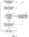
- FIG. 2 is a flow diagram of a process 200 that operates the printing system 10 to compensate for displacement errors detecting during formation of a metal object by the system.
- the process begins with the generation of image data of the metal object being formed (block 204).
- the generated image data is compared to the 3D design data of the object that was used to produce the machine-ready instructions used to operate the system and form the object (block 208). If any dimensional differences between the 3D design data and the generated image data are outside of predetermined range (block 212), the machine-ready instructions are modified to compensate for the differences outside of the predetermined range (block 220). Otherwise, the machine-ready instructions originally generated are used to form another portion of the object (block 216). When the next portion of the object is formed (block 224), such as a layer or part feature, the process is repeated.
- the machine-ready instruction modifications are performed as described above.
Landscapes
- Engineering & Computer Science (AREA)
- Chemical & Material Sciences (AREA)
- Manufacturing & Machinery (AREA)
- Materials Engineering (AREA)
- Automation & Control Theory (AREA)
- Theoretical Computer Science (AREA)
- Physics & Mathematics (AREA)
- General Physics & Mathematics (AREA)
- Human Computer Interaction (AREA)
- Mechanical Engineering (AREA)
- General Engineering & Computer Science (AREA)
- Analytical Chemistry (AREA)
- Software Systems (AREA)
- Quality & Reliability (AREA)
- Optics & Photonics (AREA)
- Artificial Intelligence (AREA)
- Data Mining & Analysis (AREA)
- Evolutionary Computation (AREA)
- Medical Informatics (AREA)
- Computer Vision & Pattern Recognition (AREA)
- Computing Systems (AREA)
- Mathematical Physics (AREA)
- Powder Metallurgy (AREA)
Applications Claiming Priority (2)
| Application Number | Priority Date | Filing Date | Title |
|---|---|---|---|
| US16/589,969 US11886759B2 (en) | 2019-10-01 | 2019-10-01 | Method and system for operating a metal drop ejecting three-dimensional (3D) object printer to compensate for drop size variations |
| EP20197617.2A EP3800539B1 (fr) | 2019-10-01 | 2020-09-22 | Procédé et système pour faire fonctionner une imprimante d'objets en trois dimensions (3d) à éjection de gouttes de métal pour compenser les variations de taille de goutte |
Related Parent Applications (1)
| Application Number | Title | Priority Date | Filing Date |
|---|---|---|---|
| EP20197617.2A Division EP3800539B1 (fr) | 2019-10-01 | 2020-09-22 | Procédé et système pour faire fonctionner une imprimante d'objets en trois dimensions (3d) à éjection de gouttes de métal pour compenser les variations de taille de goutte |
Publications (3)
| Publication Number | Publication Date |
|---|---|
| EP4477416A2 true EP4477416A2 (fr) | 2024-12-18 |
| EP4477416A3 EP4477416A3 (fr) | 2025-03-12 |
| EP4477416B1 EP4477416B1 (fr) | 2026-08-05 |
Family
ID=72615675
Family Applications (2)
| Application Number | Title | Priority Date | Filing Date |
|---|---|---|---|
| EP20197617.2A Active EP3800539B1 (fr) | 2019-10-01 | 2020-09-22 | Procédé et système pour faire fonctionner une imprimante d'objets en trois dimensions (3d) à éjection de gouttes de métal pour compenser les variations de taille de goutte |
| EP24210421.4A Active EP4477416B1 (fr) | 2019-10-01 | 2020-09-22 | Procédé et système de fonctionnement d'une imprimante d'objet tridimensionnelle (3d) à éjection de gouttes de métal pour compenser des variations de taille de goutte |
Family Applications Before (1)
| Application Number | Title | Priority Date | Filing Date |
|---|---|---|---|
| EP20197617.2A Active EP3800539B1 (fr) | 2019-10-01 | 2020-09-22 | Procédé et système pour faire fonctionner une imprimante d'objets en trois dimensions (3d) à éjection de gouttes de métal pour compenser les variations de taille de goutte |
Country Status (5)
| Country | Link |
|---|---|
| US (1) | US11886759B2 (fr) |
| EP (2) | EP3800539B1 (fr) |
| JP (1) | JP2021055184A (fr) |
| KR (1) | KR20210039291A (fr) |
| CN (1) | CN112589098B (fr) |
Families Citing this family (6)
| Publication number | Priority date | Publication date | Assignee | Title |
|---|---|---|---|---|
| EP3856494A1 (fr) * | 2018-11-02 | 2021-08-04 | Inkbit, LLC | Fabrication additive intelligente |
| US11794255B2 (en) * | 2021-01-27 | 2023-10-24 | Xerox Corporation | Method and apparatus for forming overhang structures with a metal drop ejecting three-dimensional (3D) object printer |
| US12083595B2 (en) * | 2022-05-23 | 2024-09-10 | Additive Technologies Llc | Method and apparatus for forming overhanging structures in additive manufactured parts that have an improved surface roughness |
| US20240272612A1 (en) * | 2023-02-13 | 2024-08-15 | Xerox Corporation | Machine learning feature feed rates for 3d printing |
| KR102635910B1 (ko) | 2023-03-06 | 2024-02-08 | 삼성엔지니어링 주식회사 | 건설용 3d 프린터 제어 방법 |
| US20240399515A1 (en) * | 2023-06-05 | 2024-12-05 | Additive Technologies, LLC d/b/a ADDiTEC | Perimeter and infill optimizations for liquid metal jetting 3d printing |
Family Cites Families (12)
| Publication number | Priority date | Publication date | Assignee | Title |
|---|---|---|---|---|
| US9616494B2 (en) | 2014-03-28 | 2017-04-11 | Scott Vader | Conductive liquid three dimensional printer |
| US9914264B2 (en) * | 2014-12-16 | 2018-03-13 | Xerox Corporation | System and method for missing ejector correction in three-dimensional object printing by waveform adjustment |
| US10329691B2 (en) * | 2015-02-06 | 2019-06-25 | Fernando Andres BIENZOBAS SAFFIE | System and method for generating an image in a three-dimensionally printed object |
| JP6565370B2 (ja) * | 2015-06-22 | 2019-08-28 | 株式会社リコー | 立体造形装置、立体造形方法、立体造形プログラム、および情報処理装置 |
| CN108472720A (zh) * | 2015-08-24 | 2018-08-31 | 德仕托金属有限公司 | 金属对象的三维电流体动力学打印 |
| US10315247B2 (en) * | 2015-09-24 | 2019-06-11 | Markforged, Inc. | Molten metal jetting for additive manufacturing |
| US10335991B2 (en) * | 2015-12-08 | 2019-07-02 | Xerox Corporation | System and method for operation of multi-nozzle extrusion printheads in three-dimensional object printers |
| US11014163B2 (en) * | 2017-04-14 | 2021-05-25 | Desktop Metal, Inc. | Calibration of 3D printer via computer vision |
| US20180297114A1 (en) | 2017-04-14 | 2018-10-18 | Desktop Metal, Inc. | Printed object correction via computer vision |
| WO2018200383A1 (fr) * | 2017-04-24 | 2018-11-01 | Desktop Metal, Inc. | Impression tridimensionnelle (3d) utilisant des effets de traitement mesurés avec rétroaction pour des paramètres de traitement |
| EP3581884B1 (fr) * | 2018-06-15 | 2025-08-27 | Hexagon Technology Center GmbH | Fabrication additive avec surveillance du procédé par mesure optique |
| EP3738750B1 (fr) * | 2019-05-17 | 2023-05-10 | Markforged, Inc. | Appareil et procédé d'impression 3d |
-
2019
- 2019-10-01 US US16/589,969 patent/US11886759B2/en active Active
-
2020
- 2020-09-09 JP JP2020150919A patent/JP2021055184A/ja active Pending
- 2020-09-15 CN CN202010965823.3A patent/CN112589098B/zh active Active
- 2020-09-22 EP EP20197617.2A patent/EP3800539B1/fr active Active
- 2020-09-22 KR KR1020200122602A patent/KR20210039291A/ko active Pending
- 2020-09-22 EP EP24210421.4A patent/EP4477416B1/fr active Active
Also Published As
| Publication number | Publication date |
|---|---|
| US11886759B2 (en) | 2024-01-30 |
| US20210096537A1 (en) | 2021-04-01 |
| KR20210039291A (ko) | 2021-04-09 |
| EP4477416B1 (fr) | 2026-08-05 |
| EP3800539B1 (fr) | 2024-11-06 |
| EP4477416A3 (fr) | 2025-03-12 |
| CN112589098A (zh) | 2021-04-02 |
| EP3800539C0 (fr) | 2024-11-06 |
| CN112589098B (zh) | 2024-07-16 |
| JP2021055184A (ja) | 2021-04-08 |
| EP3800539A1 (fr) | 2021-04-07 |
Similar Documents
| Publication | Publication Date | Title |
|---|---|---|
| US11565475B2 (en) | Method and system for operating a metal drop ejecting three-dimensional (3D) object printer to compensate for geometric variations that occur during an additive manufacturing process | |
| EP3800539B1 (fr) | Procédé et système pour faire fonctionner une imprimante d'objets en trois dimensions (3d) à éjection de gouttes de métal pour compenser les variations de taille de goutte | |
| JP2022084860A (ja) | 積層造形における人工知能フィードバック制御のためのシステム、方法および媒体 | |
| CN105291428B (zh) | 使用光学传感器调节三维物体打印期间的打印机的操作的系统 | |
| CA3118328A1 (fr) | Fabrication additive intelligente | |
| US12023871B2 (en) | Method for improved infilling of part interiors in objects formed by additive manufacturing systems | |
| US20240390980A1 (en) | Method for forming overhanging structures in additive manufactured parts that have an improved surface roughness | |
| EP4035805A1 (fr) | Procédé et appareil pour former des structures de surplomb avec une imprimante d'objets tridimensionnels (3d) à éjection de gouttes de métal | |
| EP4023369A1 (fr) | Imprimante d'objets tridimensionnels (3d) à éjection de chute de métal présentant un taux de dépôt de matériaux accru | |
| KR102847465B1 (ko) | 3차원 인쇄 물체의 주변부들에서 양자화 에러를 방지하도록 재료 액적 분출 3차원(3d) 물체 프린터를 동작시키기 위한 시스템 및 방법 | |
| US11760028B2 (en) | System and method for calibrating lag time in a three-dimensional object printer | |
| US11701712B2 (en) | System and method for reducing drop placement errors at perimeter features on an object in a three-dimensional (3D) object printer | |
| US11673198B2 (en) | System and method for reducing drop placement errors at perimeter features on an object in a three-dimensional (3D) object printer |
Legal Events
| Date | Code | Title | Description |
|---|---|---|---|
| PUAI | Public reference made under article 153(3) epc to a published international application that has entered the european phase |
Free format text: ORIGINAL CODE: 0009012 |
|
| STAA | Information on the status of an ep patent application or granted ep patent |
Free format text: STATUS: REQUEST FOR EXAMINATION WAS MADE |
|
| 17P | Request for examination filed |
Effective date: 20241101 |
|
| AC | Divisional application: reference to earlier application |
Ref document number: 3800539 Country of ref document: EP Kind code of ref document: P |
|
| AK | Designated contracting states |
Kind code of ref document: A2 Designated state(s): AL AT BE BG CH CY CZ DE DK EE ES FI FR GB GR HR HU IE IS IT LI LT LU LV MC MK MT NL NO PL PT RO RS SE SI SK SM TR |
|
| REG | Reference to a national code |
Ref country code: DE Ref legal event code: R079 Free format text: PREVIOUS MAIN CLASS: B33Y0030000000 Ipc: G06F0003120000 Ref document number: 602020075374 Country of ref document: DE |
|
| PUAL | Search report despatched |
Free format text: ORIGINAL CODE: 0009013 |
|
| AK | Designated contracting states |
Kind code of ref document: A3 Designated state(s): AL AT BE BG CH CY CZ DE DK EE ES FI FR GB GR HR HU IE IS IT LI LT LU LV MC MK MT NL NO PL PT RO RS SE SI SK SM TR |
|
| RIC1 | Information provided on ipc code assigned before grant |
Ipc: G05B 19/4099 20060101ALI20250203BHEP Ipc: B22F 10/85 20210101ALI20250203BHEP Ipc: B22F 10/31 20210101ALI20250203BHEP Ipc: B22F 10/22 20210101ALI20250203BHEP Ipc: B22F 12/90 20210101ALI20250203BHEP Ipc: B33Y 50/02 20150101ALI20250203BHEP Ipc: B33Y 30/00 20150101ALI20250203BHEP Ipc: B33Y 10/00 20150101ALI20250203BHEP Ipc: B29C 64/393 20170101ALI20250203BHEP Ipc: B29C 64/188 20170101ALI20250203BHEP Ipc: G06F 3/12 20060101AFI20250203BHEP |
|
| GRAP | Despatch of communication of intention to grant a patent |
Free format text: ORIGINAL CODE: EPIDOSNIGR1 |
|
| STAA | Information on the status of an ep patent application or granted ep patent |
Free format text: STATUS: GRANT OF PATENT IS INTENDED |
|
| RIC1 | Information provided on ipc code assigned before grant |
Ipc: G06F 3/12 20060101AFI20260218BHEP Ipc: B29C 64/188 20170101ALI20260218BHEP Ipc: B29C 64/393 20170101ALI20260218BHEP Ipc: B33Y 10/00 20150101ALI20260218BHEP Ipc: B33Y 30/00 20150101ALI20260218BHEP Ipc: B33Y 50/02 20150101ALI20260218BHEP Ipc: B22F 12/00 20210101ALI20260218BHEP Ipc: B22F 12/33 20210101ALI20260218BHEP Ipc: B22F 12/90 20210101ALI20260218BHEP Ipc: B22F 10/22 20210101ALI20260218BHEP Ipc: B22F 10/31 20210101ALI20260218BHEP Ipc: B22F 10/32 20210101ALI20260218BHEP Ipc: B22F 10/85 20210101ALI20260218BHEP Ipc: G05B 19/4099 20060101ALI20260218BHEP Ipc: G06N 20/00 20190101ALI20260218BHEP |
|
| INTG | Intention to grant announced |
Effective date: 20260303 |
|
| GRAS | Grant fee paid |
Free format text: ORIGINAL CODE: EPIDOSNIGR3 |
|
| GRAA | (expected) grant |
Free format text: ORIGINAL CODE: 0009210 |
|
| STAA | Information on the status of an ep patent application or granted ep patent |
Free format text: STATUS: THE PATENT HAS BEEN GRANTED |
|
| REG | Reference to a national code |
Ref country code: DE Ref legal event code: R081 Ref document number: 602020075374 Country of ref document: DE Owner name: ADDITIVE TECHNOLOGIES, LLC DBA ADDITEC, PALM C, US Free format text: FORMER OWNER: ADDITIVE TECHNOLOGIES, LLC DBA ADDITEC, DURHAM, NC, US |
|
| AC | Divisional application: reference to earlier application |
Ref document number: 3800539 Country of ref document: EP Kind code of ref document: P |
|
| AK | Designated contracting states |
Kind code of ref document: B1 Designated state(s): AL AT BE BG CH CY CZ DE DK EE ES FI FR GB GR HR HU IE IS IT LI LT LU LV MC MK MT NL NO PL PT RO RS SE SI SK SM TR |
|
| REG | Reference to a national code |
Ref country code: CH Ref legal event code: F10 Free format text: ST27 STATUS EVENT CODE: U-0-0-F10-F00 (AS PROVIDED BY THE NATIONAL OFFICE) Effective date: 20260805 |