EP4477477A2 - Agencement de pare-chocs pour un véhicule automobile - Google Patents
Agencement de pare-chocs pour un véhicule automobile Download PDFInfo
- Publication number
- EP4477477A2 EP4477477A2 EP24210688.8A EP24210688A EP4477477A2 EP 4477477 A2 EP4477477 A2 EP 4477477A2 EP 24210688 A EP24210688 A EP 24210688A EP 4477477 A2 EP4477477 A2 EP 4477477A2
- Authority
- EP
- European Patent Office
- Prior art keywords
- cross member
- auxiliary
- main cross
- auxiliary cross
- main
- Prior art date
- Legal status (The legal status is an assumption and is not a legal conclusion. Google has not performed a legal analysis and makes no representation as to the accuracy of the status listed.)
- Pending
Links
Images





Classifications
-
- B—PERFORMING OPERATIONS; TRANSPORTING
- B60—VEHICLES IN GENERAL
- B60R—VEHICLES, VEHICLE FITTINGS, OR VEHICLE PARTS, NOT OTHERWISE PROVIDED FOR
- B60R19/00—Wheel guards; Radiator guards, e.g. grilles; Obstruction removers; Fittings damping bouncing force in collisions
- B60R19/02—Bumpers, i.e. impact receiving or absorbing members for protecting vehicles or fending off blows from other vehicles or objects
- B60R19/04—Bumpers, i.e. impact receiving or absorbing members for protecting vehicles or fending off blows from other vehicles or objects formed from more than one section in a side-by-side arrangement
- B60R19/12—Bumpers, i.e. impact receiving or absorbing members for protecting vehicles or fending off blows from other vehicles or objects formed from more than one section in a side-by-side arrangement vertically spaced
-
- B—PERFORMING OPERATIONS; TRANSPORTING
- B60—VEHICLES IN GENERAL
- B60R—VEHICLES, VEHICLE FITTINGS, OR VEHICLE PARTS, NOT OTHERWISE PROVIDED FOR
- B60R19/00—Wheel guards; Radiator guards, e.g. grilles; Obstruction removers; Fittings damping bouncing force in collisions
- B60R19/02—Bumpers, i.e. impact receiving or absorbing members for protecting vehicles or fending off blows from other vehicles or objects
- B60R19/023—Details
-
- B—PERFORMING OPERATIONS; TRANSPORTING
- B60—VEHICLES IN GENERAL
- B60R—VEHICLES, VEHICLE FITTINGS, OR VEHICLE PARTS, NOT OTHERWISE PROVIDED FOR
- B60R19/00—Wheel guards; Radiator guards, e.g. grilles; Obstruction removers; Fittings damping bouncing force in collisions
- B60R19/02—Bumpers, i.e. impact receiving or absorbing members for protecting vehicles or fending off blows from other vehicles or objects
- B60R19/18—Bumpers, i.e. impact receiving or absorbing members for protecting vehicles or fending off blows from other vehicles or objects characterised by the cross-section; Means within the bumper to absorb impact
-
- B—PERFORMING OPERATIONS; TRANSPORTING
- B60—VEHICLES IN GENERAL
- B60R—VEHICLES, VEHICLE FITTINGS, OR VEHICLE PARTS, NOT OTHERWISE PROVIDED FOR
- B60R19/00—Wheel guards; Radiator guards, e.g. grilles; Obstruction removers; Fittings damping bouncing force in collisions
- B60R19/02—Bumpers, i.e. impact receiving or absorbing members for protecting vehicles or fending off blows from other vehicles or objects
- B60R19/24—Arrangements for mounting bumpers on vehicles
- B60R19/26—Arrangements for mounting bumpers on vehicles comprising yieldable mounting means
- B60R19/34—Arrangements for mounting bumpers on vehicles comprising yieldable mounting means destroyed upon impact, e.g. one-shot type
-
- B—PERFORMING OPERATIONS; TRANSPORTING
- B60—VEHICLES IN GENERAL
- B60R—VEHICLES, VEHICLE FITTINGS, OR VEHICLE PARTS, NOT OTHERWISE PROVIDED FOR
- B60R19/00—Wheel guards; Radiator guards, e.g. grilles; Obstruction removers; Fittings damping bouncing force in collisions
- B60R19/02—Bumpers, i.e. impact receiving or absorbing members for protecting vehicles or fending off blows from other vehicles or objects
- B60R19/18—Bumpers, i.e. impact receiving or absorbing members for protecting vehicles or fending off blows from other vehicles or objects characterised by the cross-section; Means within the bumper to absorb impact
- B60R2019/1806—Structural beams therefor, e.g. shock-absorbing
- B60R2019/1813—Structural beams therefor, e.g. shock-absorbing made of metal
Definitions
- the present invention relates to a bumper arrangement for a motor vehicle according to the features in the preamble of claim 1.
- a second task that is fulfilled by a bumper arrangement is the conversion of crash energy into deformation work and thus a corresponding reduction/absorption of the impact energy.
- a respective cross member is coupled to the motor vehicle via crash boxes.
- the crash boxes are arranged between a middle area and an end area of the cross member in relation to the transverse direction of the vehicle.
- the crash boxes are then usually coupled to the longitudinal members of the motor vehicle.
- the crash boxes fold like an accordion, for example, and thus convert crash energy into deformation work.
- the object of the present invention is, based on the prior art, to provide a bumper arrangement which has improved crash behavior, in particular for the MPDB crash test.
- the bumper arrangement for a motor vehicle has an upper main cross member, which is coupled to the motor vehicle via crash boxes, and a lower auxiliary cross member.
- the main cross member and the auxiliary cross member are coupled to one another via vertical struts.
- the auxiliary cross member can optionally be supported on the crash boxes.
- the auxiliary cross member can also be supported on the motor vehicle via separate lower crash supports.
- the bumper arrangement is characterized in that the main cross member and the auxiliary cross member are curved around the vertical axis at least in sections, although the main cross member and the auxiliary cross member can have different radii of curvature from one another.
- auxiliary cross member in the longitudinal direction of the vehicle towards the vehicle.
- the auxiliary cross member is thus arranged completely or in sections offset to the rear or front of the vehicle's longitudinal direction.
- the auxiliary cross member has a middle section which is offset in the vertical direction, in particular upwards or downwards.
- the main cross member can also have a middle section which has an offset in the vertical direction, and therefore in the X-direction of the vehicle. This can be designed in addition to the offset of the auxiliary cross member in the vertical direction.
- the main cross member can also have an offset in the vertical direction of the vehicle in isolation, in relation to the auxiliary cross member which runs flat in the vertical direction of the vehicle.
- the desired crash reactions with regard to energy dissipation can be adjusted according to the requirements of the respective vehicle class that is equipped with the bumper arrangement, so that the crash performance required by the manufacturer and by law is achieved.
- the main cross member and the auxiliary cross member are made in one piece and from the same material in conjunction with the vertical struts.
- the bumper arrangement is particularly suitable within the scope of the invention to manufacture the bumper arrangement as a press-formed component, in particular from a steel alloy.
- This is therefore a shell component which is produced from a blank by forming.
- the main and auxiliary cross members preferably have a profiled cross-section, in particular U-shaped or C-shaped or even hat-shaped.
- a respective locking plate can be attached to the main cross member or auxiliary cross member, possibly only in sections in relation to the longitudinal direction.
- the main cross member and the auxiliary cross member can be made in one piece and from the same material from an extruded profile, in particular from a light metal alloy.
- the corresponding curvatures can be produced by further bending processing.
- the connections that are formed via the vertical struts are a connecting web that remains between the profiles. The remaining material can be removed using cutting technology.
- the vertical struts themselves have a profiled cross-section, in particular U-shaped, C-shaped or hat-shaped. It is particularly preferred that a front web is arranged pointing away from the vehicle. This measure means that the main cross member and the auxiliary cross member are coupled together in a particularly rigid manner, which in turn increases crash performance.
- an indentation is present in the main cross member such that an initial deformation occurs when a load is applied in the longitudinal direction.
- the indentation is provided in particular on a front wall of the main cross member in relation to the longitudinal direction of the vehicle.
- two or more indentations can also be present.
- the two indentations are spaced apart from one another in the transverse direction of the vehicle.
- the two indentations are preferably arranged symmetrically to one another in relation to a central plane in the transverse direction of the vehicle.
- the indentation or indentations on the front can, on the one hand, cause an initial deformation so that the bumper arrangement is deformed accordingly in only one half in relation to the transverse direction of the vehicle.
- An initial introduction of force i.e. the initial impact force due to a deformation of the main cross member itself, can also reduce a first peak of crash energy.
- auxiliary cross member is preferably coupled to lower crash support elements.
- auxiliary cross member is coupled to additional longitudinal members or crash boxes, which in turn are supported on the motor vehicle.
- the auxiliary cross member thus provides an additional load path, which in turn introduces the forces occurring in a frontal impact into the motor vehicle more evenly and thus to a locally smaller extent, which in turn increases the overall crash performance.
- At least one additional support element is arranged on the main cross member and/or the auxiliary cross member, wherein the support element additionally supports the main cross member and/or the auxiliary cross member on the crash box or a lower crash support.
- the support element is designed in one piece and made of the same material as the main cross member or the auxiliary cross member. Through appropriate bending, the support element is then oriented rearward, particularly in the longitudinal direction of the vehicle, from the main cross member or the auxiliary cross member, and is supported on the crash box. In particular, this support takes place on the side or below or above the crash box or on a longitudinal member of the vehicle.
- the additional support element also allows the longitudinal forces occurring in the event of a frontal crash to be distributed over several load paths, which in turn increases the crash performance of the bumper arrangement according to the invention.
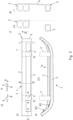
- FIG. 1 shows a bumper arrangement 1 according to the invention for a motor vehicle (not shown in more detail).
- the bumper arrangement 1 has an upper main cross member 2 and an auxiliary cross member 3 located underneath it in relation to the vertical direction Z of the motor vehicle.
- the main cross member 2 and the auxiliary cross member 3 are coupled to one another via vertical struts 4, 6.
- a vertical element 6 is provided in the respective end regions 5, which also connects the main and auxiliary cross members 2, 3 to one another.
- the main cross member 2 is coupled to the motor vehicle (not shown in more detail) via crash boxes 7.
- the vertical struts 4 can also be supported on the crash boxes 7 (not shown in more detail).
- the auxiliary cross member 3 is supported on the motor vehicle via lower crash supports 12.
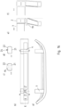
- FIG. 2a to f show a variant of the present invention.
- the bumper arrangement 1 according to the invention is shown with the Main cross member 2 and, in the vertical direction, auxiliary cross member 3 arranged underneath.
- the main cross member 2 is coupled to the motor vehicle via crash boxes 7 (not shown in detail).
- the crash boxes 7 are coupled to the front of a respective longitudinal member of the motor vehicle (not shown in detail).
- the auxiliary cross member 3 is supported on the motor vehicle via lower crash supports 12.
- the auxiliary cross member 3 arranged at the bottom is set back relative to the main cross member 2 at least in a predominantly large part of the middle section, thus between the crash boxes 7, and possibly also in the respective edge area. In the event of an impact, contact with the main cross member 2 therefore initially takes place. After deformation of the main cross member 2, an additional deformation of the auxiliary cross member 3 also takes place. Furthermore, according to Figure 2a is that the respective radius of curvature with which the main cross member 2 or auxiliary cross member 3 is curved around the vertical axis Z is different from one another. The radius of curvature of the main cross member 2 is smaller than the radius of curvature of the auxiliary cross member 3.
- the main cross member 2 is more curved than the radius of curvature of the auxiliary cross member 3.
- the main cross member 2 and auxiliary cross member 3 are coupled to one another via the respective vertical strut 4.
- a cross-section with the section line AA of the vertical strut 4 is shown. This is U-shaped in cross-section.
- a front web 8 is directed away from the motor vehicle. Legs 9 bent from the web 8 are oriented to the rear.
- the vertical strut 4 is thus stiffened. Due to the web 8 pointing forwards, an impact with an object initially occurs. Furthermore, vertical elements 6 are arranged in the respective end area. A section through the vertical elements 6 is shown in Figure 2e shown according to the section line EE. The vertical element 6 is itself L-shaped in cross section, whereby Here, too, a web 8 directed forwards and a leg 9 bent backwards from it are formed.
- the web 8 also initially hits an impacting object or barrier.
- the crash boxes 7 are in this case arranged in the vertical direction of the vehicle above the vertical struts 4.
- a vertical section is shown in Figure 2c according to the section line BB.
- the main cross member 2 is shown as a two-chamber hollow profile and the auxiliary cross member 3 as a single-chamber hollow profile.
- the section line CC in Figure 2d the end region 5, after which the main cross member 2 and the auxiliary cross member 3 are coupled to one another via a vertical element 6.
- the vertical element 6 is made in one piece and from the same material as the main cross member 2 and the auxiliary cross member 3, for example by an extrusion process from a light metal alloy, specifically an aluminum alloy.
- the Figure 2c The web 8 or the vertical element 6 which was not present according to the cutting line BB was then removed by cutting.
- Figure 3 shows such an extrusion profile in cross-section.
- a two-chamber hollow profile for forming the later main cross member 2 and a single-chamber hollow profile for forming the later auxiliary cross member 3 are coupled to one another via a vertical element 6.
- the extrusion profile initially produced in this way is then first processed using forming or bending technology in such a way that it is flattened so that, in relation to the vertical direction, the main cross member 2 is arranged above and, oriented in the vertical direction, the auxiliary cross member 3 is arranged below it and the web 8 forms the vertical element.
- a compact profile can initially be extruded in cross-section.
- Figure 4a to c show a design variant analogous to the Figure 2
- the special feature here is that a middle section 10 of the auxiliary cross member 3 is offset upwards in the vertical direction. This offset can compensate for a height difference depending on the crash requirement, for example to achieve a bumper-to-bumper test or an additional pedestrian impact test. Appropriate air ducts can also be used for Cooling elements or similar not shown in detail behind it can be used.
- the auxiliary cross member 3 which is arranged at the bottom of the vehicle vertical direction Z, has an upward offset in the middle section relative to the main cross member 2 in the vertical direction. Furthermore, as already mentioned in Figure 2f It is also possible for the auxiliary cross member 3 to have an offset to the rear in relation to the longitudinal direction X of the vehicle. However, this offset does not have to be formed; the offset in the middle section can also only be formed on its own. This concerns the height offset in the vertical direction of the vehicle, which would then be formed without an offset in the longitudinal direction of the vehicle.
- Figure 5 shows an effect essential to the invention.
- This shows the bumper arrangement 1 in a view from above in the event of a crash that has already occurred. It can be seen that the crash box 7 is already compressed.
- the main cross member 2 arranged at the top and the auxiliary cross member 3 located below it in the vertical direction are arranged further down.
- the vertical element 6 in the end region 5 has been moved towards a wheel 11 in relation to the longitudinal direction of the vehicle. This now rests, in particular with its bent leg according to Figure 2e , on a wheel 11.
- a wheel house (not shown in more detail) can be contacted. This would result in a further load path via the wheel 11 and the sill (not shown in more detail) behind it in the longitudinal direction of the vehicle.
- the main cross member 2 is not only introduced exclusively via the crash box 7, but also via a second load path, i.e. via the wheel 11 and the sill behind it in the longitudinal direction of the vehicle into the vehicle body.
- the vertical element 6 creates a particularly good support surface, so that the wheel 11 is hit in the longitudinal direction of the vehicle and the crash energy from traveling under or over the wheel 11 due to the rotational connection of the wheel 11 is reliably prevented.
- the high impact surface of the vertical element 6 in relation to the vertical direction of the vehicle in conjunction with the main and auxiliary cross members 2, 3 ensures secure support on the wheel 11. This avoids the bumper assembly 1, for example in the case of only the main cross member 2, being pushed over the Wheel 11 is lifted and accordingly no additional support would be provided on wheel 11.
- Figures 6a to d show an alternative design variant with a bumper arrangement 1 according to the invention. This can also represent an independent inventive concept, but also in combination with one or more of the embodiments according to the Figures 1 to 5 be applied.
- a bumper arrangement 1 which also has a main cross member 2 and an auxiliary cross member 3 arranged underneath it in the vertical direction Z of the motor vehicle.
- a central section of the auxiliary cross member 3 can be arranged offset downwards in the vertical direction Z, but alternatively not shown, also upwards.
- the main cross member 2 and the auxiliary cross member 3 are each coupled to one another via vertical struts 4.
- the respective end regions 5 of the main cross member 2 and the auxiliary cross member 3 are not coupled to one another separately via a vertical element 6. This can, however, be designed, but is not shown.
- the crash boxes 7, indicated by the dashed line, to which the main cross member 2 is attached, are arranged offset inwards in the transverse direction Y of the vehicle, thus offset inwards next to the vertical struts 4.
- the auxiliary cross member 3 is supported by an additional crash box 12 in the longitudinal direction of the vehicle, which is also in the Figure 6c shown in cross section.
- the cross-section of the vertical strut 4 is also U-shaped, with a web 8 directed forwards and the legs 9 bent from it.
- an additional support element 13 is provided on the main cross member 2 and also optionally shown here an additional support element 13 on the auxiliary cross member 3.
- This additional support element 13 is a piece of material formed in one piece and of the same material as the main cross member 2 or auxiliary cross member 3, which is bent as a kind of clasp and in the case of Figure 6c for the main cross member 2 below the crash box 7 and with this is coupled.
- the auxiliary cross member 3 it is bent upwards and backwards and is thus coupled with the additional crash box 12. This provides an additional support effect, but also an increase in the impact area on the front sides 14, 15 of the main cross member 2 and the auxiliary cross member 3.
- FIGS 7a to f show a further alternative embodiment of the present invention.
- a bumper arrangement 1 which has a main cross member 2 and an auxiliary cross member 3.
- the auxiliary cross member 3 is according to the plan view of Figure 7a arranged offset to the rear in the longitudinal direction of the vehicle relative to the main cross member 2.
- the main cross member 2 is supported on a motor vehicle (not shown in detail) via crash boxes 7.
- the auxiliary cross member 3 is designed as a single-chamber hollow profile.
- the vertical strut 4 and the vertical element 6 are designed in one piece and from the same material as the main cross member 2 and the auxiliary cross member 3.
- an additional portion is formed in the vertical strut 4, so that a significantly wider, forward-facing web 8 is formed on the vertical strut 4 according to the section line AA.
- a leg bent backwards can be regarded as an additional support element 13.
- This additional support element 13 is then attached to the crash box 7 located behind it, in particular shown in the Figure 7a
- the additional support element 13 can be designed in particular according to the Figure 7e be bent upwards offset to the vehicle vertical direction Z, in order to then to be supported laterally on the crash box 7.
- the crash box 7 extends in relation to the height in the vertical direction of the vehicle Z beyond the actual height of the main cross member 2, thus the height of the crash box 7 or the arrangement of the crash box 7 has a further extension in the vertical direction of the vehicle Z downwards.
- the additional support element 13, which is supported laterally on the crash box 7, is thus only bent laterally and not bent upwards in the vertical direction of the vehicle, as is the case in Figure 7e is shown.
- Figure 8 shows a further embodiment of the present invention.
- Figures 8a to f show a further embodiment of the invention. This is essentially based on the Figure 7
- the additional support is not only provided on one side of a respective crash box 7, but on both sides of the crash box 7.
- Figure 8 shows in addition that there are protruding stiffening webs on the rear side of the auxiliary cross member 2. These stiffening webs protruding from the rear in particular generate an increased moment of resistance to bending in the vertical direction of the vehicle.
- the auxiliary cross member 2 therefore has a higher stiffness due to the stiffening webs.
- Figure 9a to f show an alternative design variant to Figure 7 .
- additional support elements which are supported on the crash boxes 7. These are supported on the outside of the crash boxes 7 in the transverse direction of the vehicle. According to the example in Figure 7 These are supported on the inside by the crash boxes 7. This also initially results in a larger web 8 in a vertical element 6 according to Figures 9b and 9c
- the additional support stiffens according to Figure 9 in particular the outer end, which is prevented from bending or buckling in the transverse direction of the vehicle due to the oblique outward support.
- the additional stiffening webs are optionally arranged on the rear of the auxiliary cross member 3.
- FIG 10a to f show a further alternative or additional design variant of the present invention.
- the bumper arrangement 1 is again designed with a main cross member 2 and an auxiliary cross member 3. These two are coupled to one another via vertical struts 4.
- a towing eye 19 is arranged in an additional support element 13. This arrangement takes place according to the section line BB, shown in Figure 10e , outside the crash box 7 and outside the main cross member 2.
- the towing eye 19 is thus arranged separately from the impact beam and the crash box 7.
- a part of the Figure 10f cutting line CC, connecting vertical element 6 in the blank with a main cross member 2 and auxiliary cross member 3 and processed using cutting and bending technology so that the additional section element is formed, which is then bent backwards in the longitudinal direction of the vehicle to create an additional receiving chamber into which a towing eye 19 is then introduced.
- the towing eye 19 can, for example, be welded in the chamber.
- the towing eye 19 is, however, arranged outside the crash box 7 and outside the main cross member 2 so that it has no effect on the crash performance of the main cross member 2 and the crash box 7 itself.
- Figure 11a to d show a further supplementary and alternative embodiment of the present invention.
- a bumper arrangement 1 comprising a main cross member 2 and an auxiliary cross member 3, which are coupled to one another via vertical struts 4.
- the vertical struts 4 are, however, designed as a hollow profile 20 that is closed in cross section according to the section line AA. These then have a front wall 21 and a rear wall 22 as well as webs 23 connecting the front wall and rear wall. This is produced by first cutting the main cross member 2 and the auxiliary cross member 3 into the longitudinal section shown according to the section line CC. Figure 11d the main cross member 2 and auxiliary cross member 3 are manufactured together as a one-piece extrusion profile. The connection between The main cross member 2 and the auxiliary cross member 3 are then cut out.
- Figure 12a to e show another design variant. Basically, the same properties are present as in Figure 2 In addition to Figure 2 However, here in a central section of the main cross member 2 in the front wall 25 at least one, preferably several trigger beads 26 are formed.
- the trigger beads 26 serve to ensure that an initial deformation of only one side of the bumper arrangement 1 is carried out in the event of a corresponding impact.
- the trigger beads 26 are formed by pressing in the main cross member 2.
- the front wall 25 is pressed into this area so that the connecting webs 28 of the two-chamber hollow profile shown here are compressed. This results in a smaller depth 29 in the vehicle X direction compared to the depth 30 of the main cross member 2, if it is manufactured as an extruded profile, for example. This is also shown again in Figure 12b and e recognizable.
- three trigger beads 26 are arranged. One is arranged centrally in the transverse direction Y of the vehicle. The other two are arranged adjacent to it. Preferably, the distance 31 of the trigger beads 26 from one another is less than 10%, in particular less than 5% of the total length 32 of the main cross member 2 in the transverse direction Y of the vehicle.
- Figure 13 shows in variation to Figure 12 a central trigger bead 26 on the front wall 25 of the main cross member 2. Furthermore, a further trigger bead 26 is arranged on the rear wall 33 of the main cross member 2. The trigger bead 26 is wider here and preferably has a width 34 between 1 and 10% of the total length of the main cross member 2.
- the respective trigger bead 26 is arranged on the front and rear side of the main cross member 2 by corresponding indentations.
- the connecting webs 28 are formed accordingly.
- Figure 14a to e show a further embodiment of the bumper arrangement 1 according to the invention.
- two trigger beads 26 spaced apart from one another are formed on the main cross member 2 on the front wall. This forming is carried out by an indentation.
- the two trigger beads 26 are preferably spaced apart by a distance 35 which corresponds to 10 to 30% of the total length 32 of the main cross member 2.
- the two trigger beads 26 are spaced apart from one another symmetrically from a central longitudinal plane of the main cross member 2.
- Figure 15 shows a fastening option which can be applied to all previously mentioned bumper arrangements 1.
- the crash box 7 is designed in such a way that it overlaps the top 36 and preferably also the main cross member 2 on a bottom 37. There is then a central bolt 38 or a fastening screw, which passes through the main cross member 2 and couples it to the crash box 7. Appropriate extensions or tongues 39 are provided for overlapping, with which the crash box 7 overlaps the main cross member 2. This is shown in particular in the sectional view BB in Figure 15e .
- the auxiliary cross member 3 also has a stiffening web that extends to the rear. This stiffening web also serves to couple it to an additional crash box 7.
- a bolt 38 is provided that passes through the stiffening web and thus couples the auxiliary cross member 3 to the additional crash box 12.
- Figure 16a to f shows a further design variant.
- the respective vertical strut 4 is formed with a front wall 21 and a rear wall 22. These are welded together at the joint point 24.
- the vertical strut 4 is arranged to have a towing eye 19, which extends through the front wall and the rear wall of the vertical strut 4.
- the towing eye 19 is arranged according to the cutting line in Figure 16e below the main cross member 2 and also below the crash box 7. In the event of a frontal crash, there is no impairment of the
- Figure 17a to c shows an alternative design variant to the variant of Figure 11 .
- the bumper arrangement 1 is designed such that the vertical struts 4, which connect the main cross member 2 with the auxiliary cross member 3, in particular the cross-sectional view in Figure 17c not only have a front web and legs protruding from it, but are also folded or rolled over again at least in the area of one leg. This results in a closed hollow profile 20 in the cross section and thus increased rigidity of the vertical strut 4.
- the folded or rolled part 40 can only be processed by forming. However, it can also be coupled additionally, for example, to the web or leg, for example by gluing or welding. Overall, this results in increased rigidity of the vertical strut 4.
- a further aspect of the invention is shown between the upper main cross member 2 and the lower auxiliary cross member 3, which can also be applied to all other embodiments.
- At least one additional vertical strut 41 is shown. This is also formed in one piece and made of the same material as the upper main cross member 2 and the lower auxiliary cross member 3. Further additional vertical struts 6 can be formed between the main cross member 2 and the auxiliary cross member 3. This increases the rigidity.
- Figure 18 shows an alternative design variant of how the crash boxes 7 can be coupled in particular to the bumper arrangement 1.
- the crash box 7 as well as the additional crash support 12 are each brought up to the rear wall 45 of the main cross member 2 with a front end face 44.
- the lower additional crash support 12 which is positively attached to the rear wall of the auxiliary cross member 3.
- a respective flange 42 is provided, which protrudes from the rear wall of both the main cross member 2 and the auxiliary cross member 3 and overlaps the crash box 7 or the additional crash support 12.
- a weld seam for example in the form of a fillet weld, materially coupled.
- this variant enables an additional positive coupling, so that in particular the bumper arrangement 1 is held in a positive fit in the vertical direction Z of the vehicle.
- Figure 19 shows an analogous design variant, in which, however, the coupling is not materially bonded by a weld seam, but via a fastening bolt 46.
- two flanges are also provided, which overlap the respective crash box 7 or the auxiliary cross member 3 via additional crash support 12 or accommodate them in a fork-like manner.
- Figure 20a to c show another design variant. This is analogous to the Figure 19 with a respective fastening bolt 46, which holds the crash box 7 or the additional support. In addition, however, there is also a fork-like holder in the vehicle transverse direction Y according to Figure 20b shown.
- the crash box 7 is overlapped by the flange on the top. Furthermore, the flange also surrounds the crash box 7 laterally with its outer legs 47.
- the additional crash support 12 also has this feature. In addition, part of it overlaps the lower auxiliary cross member 3 and its front end is brought up to the front of the auxiliary cross member 3 in the longitudinal direction X of the vehicle.
Landscapes
- Engineering & Computer Science (AREA)
- Mechanical Engineering (AREA)
- Body Structure For Vehicles (AREA)
- Motor Or Generator Frames (AREA)
Applications Claiming Priority (2)
| Application Number | Priority Date | Filing Date | Title |
|---|---|---|---|
| DE102021102366.1A DE102021102366B4 (de) | 2021-02-02 | 2021-02-02 | Stoßfängeranordnung für ein Kraftfahrzeug |
| EP22153426.6A EP4035951B1 (fr) | 2021-02-02 | 2022-01-26 | Dispositif pare-chocs pour un véhicule automobile |
Related Parent Applications (1)
| Application Number | Title | Priority Date | Filing Date |
|---|---|---|---|
| EP22153426.6A Division EP4035951B1 (fr) | 2021-02-02 | 2022-01-26 | Dispositif pare-chocs pour un véhicule automobile |
Publications (2)
| Publication Number | Publication Date |
|---|---|
| EP4477477A2 true EP4477477A2 (fr) | 2024-12-18 |
| EP4477477A3 EP4477477A3 (fr) | 2025-01-15 |
Family
ID=82199334
Family Applications (2)
| Application Number | Title | Priority Date | Filing Date |
|---|---|---|---|
| EP24210688.8A Pending EP4477477A3 (fr) | 2021-02-02 | 2022-01-26 | Agencement de pare-chocs pour un véhicule automobile |
| EP22153426.6A Active EP4035951B1 (fr) | 2021-02-02 | 2022-01-26 | Dispositif pare-chocs pour un véhicule automobile |
Family Applications After (1)
| Application Number | Title | Priority Date | Filing Date |
|---|---|---|---|
| EP22153426.6A Active EP4035951B1 (fr) | 2021-02-02 | 2022-01-26 | Dispositif pare-chocs pour un véhicule automobile |
Country Status (5)
| Country | Link |
|---|---|
| US (1) | US12409800B2 (fr) |
| EP (2) | EP4477477A3 (fr) |
| CN (2) | CN119975228A (fr) |
| DE (1) | DE102021102366B4 (fr) |
| ES (1) | ES3007260T3 (fr) |
Families Citing this family (6)
| Publication number | Priority date | Publication date | Assignee | Title |
|---|---|---|---|---|
| US11072369B2 (en) | 2018-08-07 | 2021-07-27 | Sti Holdings, Inc. | Stamped rear frame bolster |
| US11110972B2 (en) | 2018-08-07 | 2021-09-07 | Sti Holdings, Inc. | Stamped rear frame bolster |
| USD979468S1 (en) * | 2019-05-17 | 2023-02-28 | Dr. Ing. H.C. F. Porsche Aktiengesellschaft | Front end of motor vehicle, toy vehicle replica and/or other replica |
| USD1087844S1 (en) | 2019-09-09 | 2025-08-12 | Sti Holdings, Inc. | Rear bolster |
| DE102022120617B4 (de) * | 2022-08-16 | 2025-03-20 | Benteler Automobiltechnik Gmbh | Stoßfängeranordnung mit endseitiger Verlängerung |
| DE102024120386B3 (de) * | 2024-07-18 | 2025-10-02 | Bayerische Motoren Werke Aktiengesellschaft | Stoßfängersystem für ein Kraftfahrzeug sowie Kraftfahrzeug mit einem solchen Stoßfängersystem |
Family Cites Families (25)
| Publication number | Priority date | Publication date | Assignee | Title |
|---|---|---|---|---|
| DE19511868A1 (de) * | 1995-03-31 | 1996-10-02 | Daimler Benz Ag | Stoßstange |
| US6062634A (en) * | 1997-11-17 | 2000-05-16 | Daimlerchrysler Corporation | Automotive energy absorbing structure |
| JP2001277963A (ja) * | 2000-03-30 | 2001-10-10 | Fuji Heavy Ind Ltd | 自動車用バンパ構造 |
| FR2829733B1 (fr) * | 2001-09-14 | 2003-11-28 | Plastic Omnium Cie | Systeme d'absorption d'energie pour vehicule automobile |
| DE10154113A1 (de) | 2001-11-03 | 2003-05-15 | Opel Adam Ag | Frontstruktur eines Kraftfahrzeuges |
| EP2082924B1 (fr) * | 2008-01-22 | 2010-11-03 | Peguform Gmbh | Traverse de pare-chocs pour véhicules automobiles |
| FR2932766B1 (fr) * | 2008-06-18 | 2010-12-10 | Faurecia Bloc Avant | Element de support de peau de bouclier ameliore pour vehicule automobile |
| DE102008039972A1 (de) * | 2008-08-27 | 2010-03-04 | Dr.Ing.H.C.F.Porsche Aktiengesellschaft | Frontstruktur eines Kraftfahrzeugs |
| DE202008014749U1 (de) * | 2008-11-06 | 2010-03-25 | Peguform Gmbh | Stoßfängerquerträger |
| DE102009058287A1 (de) | 2009-12-14 | 2011-06-16 | GM Global Technology Operations LLC, ( n. d. Ges. d. Staates Delaware ), Detroit | Vorderbau für ein Kraftfahrzeug |
| DE102011052153A1 (de) * | 2011-07-26 | 2013-01-31 | Benteler Automobiltechnik Gmbh | Verfahren zur Herstellung eines Kraftfahrzeug-Biegeträgers und Kraftfahrzeug-Biegeträger |
| DE102012211339A1 (de) | 2012-06-29 | 2014-04-24 | Bayerische Motoren Werke Aktiengesellschaft | Kraftfahrzeugkarosserie |
| DE102012019933A1 (de) | 2012-10-11 | 2014-04-17 | Volkswagen Aktiengesellschaft | Vorbaustruktur für ein Nutzkraftfahrzeug |
| DE102013101085A1 (de) | 2013-02-04 | 2014-08-07 | Benteler Automobiltechnik Gmbh | Vorderwagenstruktur eines Kraftfahrzeuges |
| DE102014107320B4 (de) * | 2014-05-23 | 2019-04-11 | Benteler Automobiltechnik Gmbh | Stoßfängeranordnung für ein Kraftfahrzeug |
| EP3254905A1 (fr) * | 2016-06-08 | 2017-12-13 | Constellium Singen GmbH | Pare- choc pour un vehicule a moteur et procede de production |
| DE102017124590B4 (de) | 2017-10-20 | 2025-07-03 | Benteler Automobiltechnik Gmbh | Einstückiger Doppelquerträger aus Extrusionsprofil |
| DE102019120327B4 (de) * | 2019-07-26 | 2022-09-08 | Kirchhoff Automotive Deutschland Gmbh | Stoßfängerquerträger für ein Fahrzeug |
| EP3858683A1 (fr) * | 2020-01-31 | 2021-08-04 | Constellium Singen GmbH | Elément de connexion pour l amélioration du comportement au crash en cas de collision entre 2 voitures |
| JP7449155B2 (ja) * | 2020-04-27 | 2024-03-13 | 株式会社Subaru | 車体前部構造 |
| DE102020130039B3 (de) | 2020-11-13 | 2022-02-03 | Benteler Automobiltechnik Gmbh | Stoßfängeranordnung |
| DE202020005403U1 (de) * | 2020-11-13 | 2021-02-04 | Benteler Automobiltechnik Gmbh | Stoßfängeranordnung |
| DE202021103264U1 (de) * | 2021-02-02 | 2021-06-28 | Benteler Automobiltechnik Gmbh | Stoßfängeranordnung für ein Kraftfahrzeug |
| DE202021103263U1 (de) * | 2021-02-02 | 2021-06-28 | Benteler Automobiltechnik Gmbh | Stoßfängeranordnung mit zusätzlicher Abstützung |
| JP7697299B2 (ja) * | 2021-07-09 | 2025-06-24 | 積水ハウス株式会社 | 建物 |
-
2021
- 2021-02-02 DE DE102021102366.1A patent/DE102021102366B4/de active Active
-
2022
- 2022-01-26 EP EP24210688.8A patent/EP4477477A3/fr active Pending
- 2022-01-26 EP EP22153426.6A patent/EP4035951B1/fr active Active
- 2022-01-26 ES ES22153426T patent/ES3007260T3/es active Active
- 2022-01-28 CN CN202510270089.1A patent/CN119975228A/zh active Pending
- 2022-01-28 CN CN202210109517.9A patent/CN114834379B/zh active Active
- 2022-02-01 US US17/590,427 patent/US12409800B2/en active Active
Also Published As
| Publication number | Publication date |
|---|---|
| CN119975228A (zh) | 2025-05-13 |
| EP4477477A3 (fr) | 2025-01-15 |
| US12409800B2 (en) | 2025-09-09 |
| EP4035951A1 (fr) | 2022-08-03 |
| EP4035951B1 (fr) | 2024-12-04 |
| CN114834379A (zh) | 2022-08-02 |
| US20220242349A1 (en) | 2022-08-04 |
| DE102021102366B4 (de) | 2024-04-18 |
| ES3007260T3 (en) | 2025-03-19 |
| CN114834379B (zh) | 2025-03-28 |
| DE102021102366A1 (de) | 2022-08-04 |
Similar Documents
| Publication | Publication Date | Title |
|---|---|---|
| EP4035951B1 (fr) | Dispositif pare-chocs pour un véhicule automobile | |
| EP4035952B1 (fr) | Agencement de pare-chocs pourvu de support supplémentaire | |
| DE102007042292B4 (de) | Plastisch verformbare Doppelzellenverbindung für die Front von Automobilen | |
| EP1840003B1 (fr) | Elément de renforcement d'un soubassement de porte de carrosserie de véhicule automobile | |
| DE202021103263U1 (de) | Stoßfängeranordnung mit zusätzlicher Abstützung | |
| DE60220110T2 (de) | Verfahren zum Herstellen einer Fahrzeugrahmenanordnung mit kastenförmigem Knautschteil | |
| DE102017124590B4 (de) | Einstückiger Doppelquerträger aus Extrusionsprofil | |
| EP4035950B1 (fr) | Agencement de pare-chocs à profilé creux d'extrémité | |
| EP3165426A1 (fr) | Ensemble pour un véhicule comprenant un châssis secondaire et une structure d'absorption de chocs | |
| DE102009006609B4 (de) | Stoßfänger für ein Kraftfahrzeug | |
| DE102010036450A1 (de) | B-Säulenverstärkung eines Kraftfahrzeugs | |
| DE202021103264U1 (de) | Stoßfängeranordnung für ein Kraftfahrzeug | |
| EP4177114B1 (fr) | Pare-chocs doté d'une tôle de renforcement intégrée | |
| DE102018008894B4 (de) | Energieabsorptions-Baueinheit für einen Kraftwagen sowie Energieabsorptionselement und Verstärkungselement hierfür | |
| DE102015105625B4 (de) | Stoßfängeranordnung für ein Kraftfahrzeug | |
| EP3031673B1 (fr) | Dispositif d'absorption d'energie pour un vehicule | |
| WO2015003983A1 (fr) | Dispositif d'absorption des impacts destiné à un véhicule automobile | |
| DE102009021964A1 (de) | Hohlprofil für eine Fahrzeugkarosserie | |
| EP4382367B1 (fr) | Profilé déformable | |
| EP4357203B1 (fr) | Ensemble pare-chocs comprenant une traverse double et un crochet de remorquage | |
| EP4049902B1 (fr) | Agencement de pare-choc pour véhicule automobile | |
| DE102004016839B4 (de) | Vorrichtung zur Aufnahme von Stoßenergie | |
| DE10108352B4 (de) | Strukturbauelement für den Fahrzeugbau | |
| DE102022120617A1 (de) | Stoßfängeranordnung mit endseitiger Verlängerung | |
| EP3984831A1 (fr) | Dispositif pare-chocs pour un véhicule automobile |
Legal Events
| Date | Code | Title | Description |
|---|---|---|---|
| PUAI | Public reference made under article 153(3) epc to a published international application that has entered the european phase |
Free format text: ORIGINAL CODE: 0009012 |
|
| STAA | Information on the status of an ep patent application or granted ep patent |
Free format text: STATUS: THE APPLICATION HAS BEEN PUBLISHED |
|
| REG | Reference to a national code |
Ref country code: DE Ref legal event code: R079 Free format text: PREVIOUS MAIN CLASS: B60R0019180000 Ipc: B60R0019120000 |
|
| PUAL | Search report despatched |
Free format text: ORIGINAL CODE: 0009013 |
|
| AC | Divisional application: reference to earlier application |
Ref document number: 4035951 Country of ref document: EP Kind code of ref document: P |
|
| AK | Designated contracting states |
Kind code of ref document: A2 Designated state(s): AL AT BE BG CH CY CZ DE DK EE ES FI FR GB GR HR HU IE IS IT LI LT LU LV MC MK MT NL NO PL PT RO RS SE SI SK SM TR |
|
| AK | Designated contracting states |
Kind code of ref document: A3 Designated state(s): AL AT BE BG CH CY CZ DE DK EE ES FI FR GB GR HR HU IE IS IT LI LT LU LV MC MK MT NL NO PL PT RO RS SE SI SK SM TR |
|
| RIC1 | Information provided on ipc code assigned before grant |
Ipc: B60R 19/18 20060101ALI20241210BHEP Ipc: B60R 19/12 20060101AFI20241210BHEP |
|
| STAA | Information on the status of an ep patent application or granted ep patent |
Free format text: STATUS: REQUEST FOR EXAMINATION WAS MADE |
|
| 17P | Request for examination filed |
Effective date: 20250710 |