EP4477479A1 - Coussin gonflable de véhicule - Google Patents
Coussin gonflable de véhicule Download PDFInfo
- Publication number
- EP4477479A1 EP4477479A1 EP23210496.8A EP23210496A EP4477479A1 EP 4477479 A1 EP4477479 A1 EP 4477479A1 EP 23210496 A EP23210496 A EP 23210496A EP 4477479 A1 EP4477479 A1 EP 4477479A1
- Authority
- EP
- European Patent Office
- Prior art keywords
- seat
- chamber
- driver
- lower portion
- vehicle airbag
- Prior art date
- Legal status (The legal status is an assumption and is not a legal conclusion. Google has not performed a legal analysis and makes no representation as to the accuracy of the status listed.)
- Granted
Links
Images



Classifications
-
- B—PERFORMING OPERATIONS; TRANSPORTING
- B60—VEHICLES IN GENERAL
- B60R—VEHICLES, VEHICLE FITTINGS, OR VEHICLE PARTS, NOT OTHERWISE PROVIDED FOR
- B60R21/00—Arrangements or fittings on vehicles for protecting or preventing injuries to occupants or pedestrians in case of accidents or other traffic risks
- B60R21/02—Occupant safety arrangements or fittings, e.g. crash pads
- B60R21/16—Inflatable occupant restraints or confinements designed to inflate upon impact or impending impact, e.g. air bags
- B60R21/23—Inflatable members
- B60R21/231—Inflatable members characterised by their shape, construction or spatial configuration
- B60R21/23138—Inflatable members characterised by their shape, construction or spatial configuration specially adapted for side protection
-
- B—PERFORMING OPERATIONS; TRANSPORTING
- B60—VEHICLES IN GENERAL
- B60R—VEHICLES, VEHICLE FITTINGS, OR VEHICLE PARTS, NOT OTHERWISE PROVIDED FOR
- B60R21/00—Arrangements or fittings on vehicles for protecting or preventing injuries to occupants or pedestrians in case of accidents or other traffic risks
- B60R21/02—Occupant safety arrangements or fittings, e.g. crash pads
- B60R21/16—Inflatable occupant restraints or confinements designed to inflate upon impact or impending impact, e.g. air bags
- B60R21/20—Arrangements for storing inflatable members in their non-use or deflated condition; Arrangement or mounting of air bag modules or components
- B60R21/217—Inflation fluid source retainers, e.g. reaction canisters; Connection of bags, covers, diffusers or inflation fluid sources therewith or together
-
- B—PERFORMING OPERATIONS; TRANSPORTING
- B60—VEHICLES IN GENERAL
- B60R—VEHICLES, VEHICLE FITTINGS, OR VEHICLE PARTS, NOT OTHERWISE PROVIDED FOR
- B60R21/00—Arrangements or fittings on vehicles for protecting or preventing injuries to occupants or pedestrians in case of accidents or other traffic risks
- B60R21/02—Occupant safety arrangements or fittings, e.g. crash pads
- B60R21/16—Inflatable occupant restraints or confinements designed to inflate upon impact or impending impact, e.g. air bags
- B60R21/23—Inflatable members
- B60R21/231—Inflatable members characterised by their shape, construction or spatial configuration
- B60R21/233—Inflatable members characterised by their shape, construction or spatial configuration comprising a plurality of individual compartments; comprising two or more bag-like members, one within the other
-
- B—PERFORMING OPERATIONS; TRANSPORTING
- B60—VEHICLES IN GENERAL
- B60R—VEHICLES, VEHICLE FITTINGS, OR VEHICLE PARTS, NOT OTHERWISE PROVIDED FOR
- B60R21/00—Arrangements or fittings on vehicles for protecting or preventing injuries to occupants or pedestrians in case of accidents or other traffic risks
- B60R21/02—Occupant safety arrangements or fittings, e.g. crash pads
- B60R21/16—Inflatable occupant restraints or confinements designed to inflate upon impact or impending impact, e.g. air bags
- B60R21/23—Inflatable members
- B60R21/231—Inflatable members characterised by their shape, construction or spatial configuration
- B60R21/2334—Expansion control features
- B60R21/2338—Tethers
-
- B—PERFORMING OPERATIONS; TRANSPORTING
- B60—VEHICLES IN GENERAL
- B60R—VEHICLES, VEHICLE FITTINGS, OR VEHICLE PARTS, NOT OTHERWISE PROVIDED FOR
- B60R21/00—Arrangements or fittings on vehicles for protecting or preventing injuries to occupants or pedestrians in case of accidents or other traffic risks
- B60R2021/003—Arrangements or fittings on vehicles for protecting or preventing injuries to occupants or pedestrians in case of accidents or other traffic risks characterised by occupant or pedestian
- B60R2021/0039—Body parts of the occupant or pedestrian affected by the accident
- B60R2021/0048—Head
-
- B—PERFORMING OPERATIONS; TRANSPORTING
- B60—VEHICLES IN GENERAL
- B60R—VEHICLES, VEHICLE FITTINGS, OR VEHICLE PARTS, NOT OTHERWISE PROVIDED FOR
- B60R21/00—Arrangements or fittings on vehicles for protecting or preventing injuries to occupants or pedestrians in case of accidents or other traffic risks
- B60R21/02—Occupant safety arrangements or fittings, e.g. crash pads
- B60R21/16—Inflatable occupant restraints or confinements designed to inflate upon impact or impending impact, e.g. air bags
- B60R21/23—Inflatable members
- B60R21/231—Inflatable members characterised by their shape, construction or spatial configuration
- B60R21/23138—Inflatable members characterised by their shape, construction or spatial configuration specially adapted for side protection
- B60R2021/23146—Inflatable members characterised by their shape, construction or spatial configuration specially adapted for side protection seat mounted
-
- B—PERFORMING OPERATIONS; TRANSPORTING
- B60—VEHICLES IN GENERAL
- B60R—VEHICLES, VEHICLE FITTINGS, OR VEHICLE PARTS, NOT OTHERWISE PROVIDED FOR
- B60R21/00—Arrangements or fittings on vehicles for protecting or preventing injuries to occupants or pedestrians in case of accidents or other traffic risks
- B60R21/02—Occupant safety arrangements or fittings, e.g. crash pads
- B60R21/16—Inflatable occupant restraints or confinements designed to inflate upon impact or impending impact, e.g. air bags
- B60R21/23—Inflatable members
- B60R21/231—Inflatable members characterised by their shape, construction or spatial configuration
- B60R2021/23161—Inflatable members characterised by their shape, construction or spatial configuration specially adapted for protecting at least two passengers, e.g. preventing them from hitting each other
-
- B—PERFORMING OPERATIONS; TRANSPORTING
- B60—VEHICLES IN GENERAL
- B60R—VEHICLES, VEHICLE FITTINGS, OR VEHICLE PARTS, NOT OTHERWISE PROVIDED FOR
- B60R21/00—Arrangements or fittings on vehicles for protecting or preventing injuries to occupants or pedestrians in case of accidents or other traffic risks
- B60R21/02—Occupant safety arrangements or fittings, e.g. crash pads
- B60R21/16—Inflatable occupant restraints or confinements designed to inflate upon impact or impending impact, e.g. air bags
- B60R21/23—Inflatable members
- B60R21/231—Inflatable members characterised by their shape, construction or spatial configuration
- B60R21/233—Inflatable members characterised by their shape, construction or spatial configuration comprising a plurality of individual compartments; comprising two or more bag-like members, one within the other
- B60R2021/23308—Inflatable members characterised by their shape, construction or spatial configuration comprising a plurality of individual compartments; comprising two or more bag-like members, one within the other the individual compartments defining the external shape of the bag
-
- B—PERFORMING OPERATIONS; TRANSPORTING
- B60—VEHICLES IN GENERAL
- B60R—VEHICLES, VEHICLE FITTINGS, OR VEHICLE PARTS, NOT OTHERWISE PROVIDED FOR
- B60R21/00—Arrangements or fittings on vehicles for protecting or preventing injuries to occupants or pedestrians in case of accidents or other traffic risks
- B60R21/02—Occupant safety arrangements or fittings, e.g. crash pads
- B60R21/16—Inflatable occupant restraints or confinements designed to inflate upon impact or impending impact, e.g. air bags
- B60R21/23—Inflatable members
- B60R21/231—Inflatable members characterised by their shape, construction or spatial configuration
- B60R21/2334—Expansion control features
- B60R21/2338—Tethers
- B60R2021/23386—External tether means
-
- B—PERFORMING OPERATIONS; TRANSPORTING
- B60—VEHICLES IN GENERAL
- B60R—VEHICLES, VEHICLE FITTINGS, OR VEHICLE PARTS, NOT OTHERWISE PROVIDED FOR
- B60R21/00—Arrangements or fittings on vehicles for protecting or preventing injuries to occupants or pedestrians in case of accidents or other traffic risks
- B60R21/02—Occupant safety arrangements or fittings, e.g. crash pads
- B60R21/16—Inflatable occupant restraints or confinements designed to inflate upon impact or impending impact, e.g. air bags
- B60R21/23—Inflatable members
- B60R21/237—Inflatable members characterised by the way they are folded
Definitions
- the present invention relates to a vehicle airbag, and more specifically, to a vehicle airbag disposed between a driver's seat and a passenger seat.
- an airbag In general, when a car accident occurs, an airbag is designed to protect an occupant by rapidly expelling gas and rapidly inflating a deflated airbag in response to a signal from a collision sensor.
- a side airbag is required to be designed to meet a standard required for oblique crashes according to North American New Car Assessment Program (NCAP).
- NCAP North American New Car Assessment Program
- the present invention is directed to providing a vehicle airbag that may safely protect an occupant in the event of a side or oblique crash.
- a vehicle airbag including a lower chamber installed on a side of a driver's seat and is configured to expand from a driver's seat toward a passenger seat to fill a space between the driver's seat and the passenger seat when deployed, and an upper chamber that expands upwardly from a side of the lower chamber proximate the passenger seat and includes an upper portion that extends toward the driver's seat, wherein the lower chamber surrounds a central area in the space between the driver's seat and the passenger seat that includes an air pocket filled with air and is configured to absorb an impact applied to the lower chamber.
- the lower chamber may include a first lower portion disposed on a side of the driver's seat, a second lower portion disposed on a side of the passenger seat and a third lower portion disposed between the first lower portion and the second lower portion and connecting the first lower portion and the second lower portion.
- the first lower portion may extend from the side of the driver's seat in a front-rear direction of a vehicle
- the second lower portion may extend from the side of the passenger seat in the front-rear direction of the vehicle
- the third lower portion may be connected to a rear end portion of the first lower portion and a rear end portion of the second lower portion.
- the lower chamber may include a lower tether that is connected to an inner side of the first lower portion and an inner side of the second lower portion, and the lower tether may pull and restrain the first lower portion and the second lower portion so that the lower chamber maintains a " ⁇ "-shaped bent shape when inflated.
- the first lower portion may be connected to an inflator mounted on the driver's seat.
- the upper chamber may include a first upper portion that extends upwardly from the second lower portion and a second upper portion that extends from an upper portion of the first upper portion towards the driver's seat.
- the upper chamber may include an upper tether that is joined to an inner side of the first upper portion and an inner side of the second upper portion, and the upper tether may pull and restrain the first upper portion and the second upper portion so that the upper chamber maintains a bent shape when inflated.
- the second upper portion may further include a third upper portion that is bent at an end portion of the second upper portion and extends downward, and the upper tether may be connected to the inner side of the first upper portion and an inner side of the third upper portion.
- a gap between the first lower portion and the second lower portion may be adjusted by adjusting a length of the lower tether.
- the lower chamber When deployed, the lower chamber may support the occupant's torso to restrain lateral movement, and the upper chamber may support and restrain the occupant's head.
- first, second, A, B, (a), (b) or the like may be used herein to describe components.
- Each of these terminologies is not used to define an essence, order or sequence of a corresponding component but used merely to distinguish the corresponding component from other component(s).
- a first component may be referred to as a second component, and similarly the second component may also be referred to as the first component.
- any one element in a case in which any one element is described as being formed on or under another element, such a description includes both a case in which the two elements are formed in direct contact with each other and a case in which the two elements are in indirect contact with each other with one or more other elements interposed between the two elements.
- such a description may include a case in which the one element is formed at an upper side or a lower side with respect to another element.
- FIG. 1 is a schematic perspective view illustrating a vehicle airbag according to an embodiment of the present invention
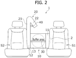
- FIG. 2 is a schematic front view illustrating a state in which the vehicle airbag is disposed between a driver's seat and a passenger seat
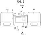
- FIG. 3 is a schematic plan view illustrating the state in which the vehicle airbag is disposed between the driver's seat and the passenger seat.
- a vehicle airbag 1 may be a center side airbag for protecting an occupant between a driver's seat S1 and a passenger seat S2.
- the airbag 1 may be installed on a seatback side of the driver's seat S1.
- the vehicle airbag 1 may include a lower chamber 10 and an upper chamber 20.
- the lower chamber 10 is expanded by the gas generated from an inflator 2 and may be deployed from the driver's seat S1 toward the passenger seat S2. Also, the lower chamber may be disposed to fill a space between the driver's seat S1 and the passenger seat S2.
- the lower chamber 10 may include a first lower portion 11 disposed on a side of the driver's seat S1, a second lower portion 12 disposed on a side of the passenger seat S2, and a third lower portion 13 disposed between the first lower portion 11 and the second lower portion 12 and connecting the first lower portion 11 and the second lower portion 12.
- the first lower portion 11 may be connected to the inflator 2 mounted on the driver's seat S1.
- the first lower portion 11 extends from the side of the driver's seat S1 in a front-rear direction of a vehicle
- the second lower portion 12 extends in the front-rear direction of the vehicle from the side of the passenger seat S2. That is, the first lower portion 11 and the second lower portion 12 may extend approximately parallel to each other in a structure facing each other in the space between the driver's seat S1 and the passenger seat S2.
- the third lower portion 13 may be connected to a rear end portion of the first lower portion 11 and a rear end portion of the second lower portion 12. That is, the third lower portion 13 can be arranged in a direction approximately perpendicular to the extension direction of the first lower portion 11 and the second lower portion 12.
- the lower chamber 10 is expanded by gas, and the first lower portion 11, the second lower portion 12, and the third lower portion 13 may be deployed to form a structure bent in an approximate " ⁇ " shape.
- the third lower portion 13 is connected to a rear end portion of each of the first lower portion 11 and the second lower portion 12, but it is not limited thereto. In some embodiments, the third lower portion 13 may be connected to a front end portion of each of the first lower portion 11 and the second lower portion 12.
- the lower chamber 10 may be provided with a lower tether 30 that is joined and connected to the inner side of the first lower portion 11 and the inner side of the second lower portion 12.
- the lower tether 30 may be connected to the lower chamber 10 through sewing.
- the lower tether 30 may be disposed on the front end portion facing the third lower portion 13 between the first lower portion 11 and the second lower portion 12.
- the lower tether 30 may pull and restrain the first lower portion 11 and the second lower portion 12 so that the lower chamber 10 maintains a " ⁇ "-shaped bent shape when the lower chamber is inflated.
- a gap between the first lower portion 11 and the second lower portion 12 may be adjusted by adjusting a length of the lower tether 30.
- the lower chamber 10 and the lower tether 30 may each be made of a flexible fabric material. Additionally, the lower chamber 10 and the lower tether 30 may each be made of a synthetic fiber material, but the material is not limited thereto.
- the lower chamber 10 is disposed to fill the space between the driver's seat S1 and the passenger seat S2 when deployed, which supports an occupant's torso and restrains lateral movement, thereby collisions between occupants and injuries can be prevented.
- a central area surrounded by the lower chamber 10 in the space between the driver's seat S1 and the passenger seat S2 includes an air pocket filled with air and is configured to absorb an impact applied to the lower chamber 10.
- the inner central area surrounded by the first lower portion 11, the second lower portion 12, and the third lower portion 13 opens to the front of a vehicle and forms a buffer area filled with air. Accordingly, an impact applied to the lower chamber by the occupants may be primarily absorbed by the lower chamber 10 and secondarily absorbed by the buffer area that constitutes the air pocket.
- the upper chamber 20 expands from the lower chamber 10 from the side of the passenger seat S2 to above the lower chamber 10 and may be deployed toward the driver's seat S1.
- the upper chamber 20 may include a first upper portion 21 that is connected to the second lower portion 12 and extends upward from the second lower portion 12, and a second upper portion 22 that is bent from the first upper portion 21 and extends toward the driver's seat S1.
- the first upper portion 21 extends from the side of the passenger seat S2 to the upper part of the vehicle in parallel with the second lower portion 12, and the second upper portion 22 may extend by bending from the end of the first upper portion 21 toward the driver's seat S1.
- the upper chamber 20 is expanded by gas, and the first upper portion 21 and the second upper portion 22 may be deployed to form a structure bent in an approximate " ⁇ " shape.
- the first upper portion 21 is connected to the second lower portion 12 and illustrated as extending from the second lower portion 12, but it is not limited thereto, and it is also possible to extend from the first lower portion 11.
- the second upper portion 22 may be bent and extended toward passenger seat S2.
- the upper chamber 20 may be provided with an upper tether 40 connected to the inner side of the first upper portion 21 and the inner side of the second upper portion 22.
- the upper tether 40 may be connected to the upper chamber 20 through sewing.
- the upper tether 40 may pull and restrain the first upper portion 21 and the second upper portion 22 so that the upper chamber 20 maintains a "A"-shaped bent shape while the upper chamber 20 is inflated.
- a gap between the first upper portion 21 and the second upper portion 22 may be adjusted by adjusting a length of the upper tether 40.
- the upper chamber 20 and the upper tether 40 may each be made of a flexible fabric material. Additionally, the upper chamber 20 and the upper tether 40 may each be made of a synthetic fiber material, but the material is not limited thereto.
- the upper chamber 20 disposed in the space between the driver's seat S1 and the passenger seat S2 supports an occupant's torso and restrains lateral movement when deployed, thereby collisions between occupants and injuries can be prevented.
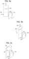
- FIGS. 4A and 4B schematically show a panel 100 constituting the vehicle airbag 1 according to the embodiment.
- the panel 100 may have a structure in which a first panel 110 and a second panel 120 are connected in a left-right symmetrical manner based on a central fold line L.
- the first panel 110 and the second panel 120 may be cut into an approximate "L" shape with a horizontal section A1 and a vertical section A2. Then, in a state in which the first panel 110 and the second panel 120 are folded along the fold line L, the airbag 1 may be formed by sewing along the edges of the first panel 110 and the second panel 120.
- the horizontal section A1 of the first panel 110 and the second panel 120 may constitute the lower chamber 10, and the vertical section A2 may constitute the upper chamber 20.
- first inactive areas R1 may be formed in the horizontal section A1.
- the first inactive area R1 may be formed by joining the first panel 110 and the second panel 120 in the vertical direction perpendicular to the horizontal section A1.
- At least one second inactive area R2 may be formed in the vertical section A2.
- the second inactive area R2 may be formed by joining the first panel 110 and the second panel 120 in a lateral direction perpendicular to the vertical section A2.
- a passage P through which gas passes may be provided between the edge of the horizontal section A1 and the first inactive area R1 and provided between the edge of the vertical section A2 and the second inactive area R2.
- assembly holes 111 and 121 where inflator 2 is assembled are formed, and on the other side, one end of the lower tether 30 may be connected and fixed.
- one end of the upper tether 40 may be connected and fixed to the end of vertical section A2.
- the horizontal section A1 is folded into a " ⁇ " shape based on the first inactive area R1, and the lower chamber 10 may be completed by connecting the other end of the lower tether 30.
- the vertical section A2 is folded into a " ⁇ " shape based on the second inactive area R2, and the upper chamber 20 may be completed by connecting the other end of the upper tether 40.
- FIGS. 6 and 7 schematically show a modified example of the upper chamber 20.
- FIG. 6 is a schematic perspective view illustrating a modified example of an upper chamber in the vehicle airbag according to the embodiment of the present invention
- FIG. 7 is a schematic front view illustrating the vehicle airbag of FIG. 6 .
- the upper chamber 20 may further include a third upper portion 23 that is bent at the end portion of the second upper portion 22 and extends downward.
- the upper tether 40 may be connected to the inner side of the first upper portion 21 and the inner side of the third upper portion 23.
- the upper tether 40 may pull and restrain the first upper portion 21 and the third upper portion 23 so that the upper chamber 20 maintains a " ⁇ "-shaped bent shape while the upper chamber 20 is inflated.
- injuries can be prevented by preventing occupants from colliding with each other through the lower chamber 10 and upper chamber 20 deployed in the space between the driver's seat S1 and the passenger seat S2.
- the lower chamber 10 is arranged to fill the space between the driver's seat S1 and the passenger seat S2 when deployed, it is possible to prevent the airbag 1 from falling into the passenger seat S2 due to an impact from the occupant in the driver's seat S1, or the airbag 1 from falling into the driver's seat S1 due to an impact from the occupant in the passenger seat S2. Accordingly, the driver's seat S1 occupant or the passenger seat S2 occupant can be protected more effectively.
- the lower chamber 10 and the upper chamber 20 are configured to be integrally connected by a panel 100 having a single structure, the overall structure is simple, therefore the problem of abnormal deployment of the airbag does not occur, and the manufacturing process is simple, thereby providing the effect of improving productivity.
- a vehicle airbag that can safely protect occupants in the event of a side or oblique crash.
Landscapes
- Engineering & Computer Science (AREA)
- Mechanical Engineering (AREA)
- Air Bags (AREA)
Applications Claiming Priority (1)
| Application Number | Priority Date | Filing Date | Title |
|---|---|---|---|
| KR1020230074593A KR20240175023A (ko) | 2023-06-12 | 2023-06-12 | 차량용 에어백 |
Publications (2)
| Publication Number | Publication Date |
|---|---|
| EP4477479A1 true EP4477479A1 (fr) | 2024-12-18 |
| EP4477479B1 EP4477479B1 (fr) | 2025-12-31 |
Family
ID=88839075
Family Applications (1)
| Application Number | Title | Priority Date | Filing Date |
|---|---|---|---|
| EP23210496.8A Active EP4477479B1 (fr) | 2023-06-12 | 2023-11-17 | Coussin gonflable de véhicule |
Country Status (4)
| Country | Link |
|---|---|
| US (1) | US12275365B2 (fr) |
| EP (1) | EP4477479B1 (fr) |
| KR (1) | KR20240175023A (fr) |
| CN (1) | CN221340520U (fr) |
Citations (5)
| Publication number | Priority date | Publication date | Assignee | Title |
|---|---|---|---|---|
| US20190061676A1 (en) * | 2017-08-24 | 2019-02-28 | Hyundai Motor Company | Airbag for a vehicle |
| WO2019110705A1 (fr) * | 2017-12-08 | 2019-06-13 | Trw Automotive Gmbh | Sac gonflable latéral et système de retenue de l'occupant d'un véhicule à l'aide d'un sac gonflable latéral |
| EP3838689A1 (fr) * | 2018-08-14 | 2021-06-23 | Autoliv Development AB | Dispositif de coussin de sécurité gonflable latéral |
| DE102020206551A1 (de) * | 2020-05-26 | 2021-12-02 | Joyson Safety Systems Germany Gmbh | Gassack für ein Fahrzeuginsassen-Rückhaltesystem eines Kraftfahrzeugs |
| US20220176904A1 (en) * | 2020-12-08 | 2022-06-09 | Autoliv Asp, Inc. | Far-side airbag assemblies with pillow and sail |
Family Cites Families (2)
| Publication number | Priority date | Publication date | Assignee | Title |
|---|---|---|---|---|
| WO2020255817A1 (fr) * | 2019-06-20 | 2020-12-24 | 芦森工業株式会社 | Dispositif de coussin de sécurité gonflable latéral |
| KR20220048805A (ko) * | 2020-10-13 | 2022-04-20 | 현대자동차주식회사 | 에어백 장치 |
-
2023
- 2023-06-12 KR KR1020230074593A patent/KR20240175023A/ko active Pending
- 2023-11-09 US US18/505,484 patent/US12275365B2/en active Active
- 2023-11-17 EP EP23210496.8A patent/EP4477479B1/fr active Active
- 2023-12-12 CN CN202323380969.XU patent/CN221340520U/zh active Active
Patent Citations (5)
| Publication number | Priority date | Publication date | Assignee | Title |
|---|---|---|---|---|
| US20190061676A1 (en) * | 2017-08-24 | 2019-02-28 | Hyundai Motor Company | Airbag for a vehicle |
| WO2019110705A1 (fr) * | 2017-12-08 | 2019-06-13 | Trw Automotive Gmbh | Sac gonflable latéral et système de retenue de l'occupant d'un véhicule à l'aide d'un sac gonflable latéral |
| EP3838689A1 (fr) * | 2018-08-14 | 2021-06-23 | Autoliv Development AB | Dispositif de coussin de sécurité gonflable latéral |
| DE102020206551A1 (de) * | 2020-05-26 | 2021-12-02 | Joyson Safety Systems Germany Gmbh | Gassack für ein Fahrzeuginsassen-Rückhaltesystem eines Kraftfahrzeugs |
| US20220176904A1 (en) * | 2020-12-08 | 2022-06-09 | Autoliv Asp, Inc. | Far-side airbag assemblies with pillow and sail |
Also Published As
| Publication number | Publication date |
|---|---|
| US20240409056A1 (en) | 2024-12-12 |
| KR20240175023A (ko) | 2024-12-19 |
| US12275365B2 (en) | 2025-04-15 |
| CN221340520U (zh) | 2024-07-16 |
| EP4477479B1 (fr) | 2025-12-31 |
Similar Documents
| Publication | Publication Date | Title |
|---|---|---|
| KR102545853B1 (ko) | 루프탑 에어백 장치 | |
| CN106965766B (zh) | 车辆斜向碰撞吸收系统 | |
| EP4094999B1 (fr) | Siège du véhicule avec dispositif airbag intégré | |
| US10703325B2 (en) | Multi-chambered side airbag assemblies | |
| KR102614144B1 (ko) | 차량 테이블용 에어백 | |
| US20190016291A1 (en) | Frontal airbag assemblies | |
| US20140265270A1 (en) | Fold over design for small overlap | |
| US10682973B2 (en) | Vehicle knee airbag device and knee airbag folding method | |
| EP4090559B1 (fr) | Véhicule comportant un siège et un ensemble de coussin gonflable | |
| JP2017222185A (ja) | 車両用エアバッグ装置 | |
| JP6540647B2 (ja) | 車両用カーテンエアバッグ装置 | |
| JP7275166B2 (ja) | 調節可能なヘッドレスト及び一体型後部シートエアバッグを有する車両用シート | |
| US10723303B2 (en) | Vehicle curtain airbag device | |
| KR101807660B1 (ko) | 자동차의 조수석 에어백 | |
| KR20230082657A (ko) | 에어백 장치 | |
| US6863299B2 (en) | Overhead airbag system and method | |
| CN110871765B (zh) | 气囊装置 | |
| KR20220066338A (ko) | 커튼 에어백 조립체 | |
| KR20190070174A (ko) | 자동차의 커튼 에어백 | |
| EP4477479A1 (fr) | Coussin gonflable de véhicule | |
| WO2022219983A1 (fr) | Dispositif de coussin de sécurité gonflable | |
| US12269412B2 (en) | Side airbag | |
| US12103486B1 (en) | Airbag cushion and side airbag device having the same | |
| JP7411602B2 (ja) | エアバッグ装置 | |
| KR102626944B1 (ko) | 자동차의 파 사이드 에어백 장치 및 그의 폴딩 방법 |
Legal Events
| Date | Code | Title | Description |
|---|---|---|---|
| PUAI | Public reference made under article 153(3) epc to a published international application that has entered the european phase |
Free format text: ORIGINAL CODE: 0009012 |
|
| STAA | Information on the status of an ep patent application or granted ep patent |
Free format text: STATUS: THE APPLICATION HAS BEEN PUBLISHED |
|
| AK | Designated contracting states |
Kind code of ref document: A1 Designated state(s): AL AT BE BG CH CY CZ DE DK EE ES FI FR GB GR HR HU IE IS IT LI LT LU LV MC ME MK MT NL NO PL PT RO RS SE SI SK SM TR |
|
| STAA | Information on the status of an ep patent application or granted ep patent |
Free format text: STATUS: REQUEST FOR EXAMINATION WAS MADE |
|
| 17P | Request for examination filed |
Effective date: 20250226 |
|
| RIC1 | Information provided on ipc code assigned before grant |
Ipc: B60R 21/2338 20110101ALI20250423BHEP Ipc: B60R 21/231 20110101AFI20250423BHEP |
|
| GRAP | Despatch of communication of intention to grant a patent |
Free format text: ORIGINAL CODE: EPIDOSNIGR1 |
|
| STAA | Information on the status of an ep patent application or granted ep patent |
Free format text: STATUS: GRANT OF PATENT IS INTENDED |
|
| INTG | Intention to grant announced |
Effective date: 20250623 |
|
| P01 | Opt-out of the competence of the unified patent court (upc) registered |
Free format text: CASE NUMBER: UPC_APP_5459_4477479/2025 Effective date: 20250901 |
|
| GRAS | Grant fee paid |
Free format text: ORIGINAL CODE: EPIDOSNIGR3 |
|
| GRAA | (expected) grant |
Free format text: ORIGINAL CODE: 0009210 |
|
| STAA | Information on the status of an ep patent application or granted ep patent |
Free format text: STATUS: THE PATENT HAS BEEN GRANTED |
|
| AK | Designated contracting states |
Kind code of ref document: B1 Designated state(s): AL AT BE BG CH CY CZ DE DK EE ES FI FR GB GR HR HU IE IS IT LI LT LU LV MC ME MK MT NL NO PL PT RO RS SE SI SK SM TR |
|
| REG | Reference to a national code |
Ref country code: CH Ref legal event code: F10 Free format text: ST27 STATUS EVENT CODE: U-0-0-F10-F00 (AS PROVIDED BY THE NATIONAL OFFICE) Effective date: 20251231 Ref country code: GB Ref legal event code: FG4D |
|
| REG | Reference to a national code |
Ref country code: DE Ref legal event code: R096 Ref document number: 602023010408 Country of ref document: DE |
|
| REG | Reference to a national code |
Ref country code: IE Ref legal event code: FG4D |
|
| REG | Reference to a national code |
Ref country code: LT Ref legal event code: MG9D |
|
| PG25 | Lapsed in a contracting state [announced via postgrant information from national office to epo] |
Ref country code: NO Free format text: LAPSE BECAUSE OF FAILURE TO SUBMIT A TRANSLATION OF THE DESCRIPTION OR TO PAY THE FEE WITHIN THE PRESCRIBED TIME-LIMIT Effective date: 20260331 |
|
| PG25 | Lapsed in a contracting state [announced via postgrant information from national office to epo] |
Ref country code: FI Free format text: LAPSE BECAUSE OF FAILURE TO SUBMIT A TRANSLATION OF THE DESCRIPTION OR TO PAY THE FEE WITHIN THE PRESCRIBED TIME-LIMIT Effective date: 20251231 Ref country code: HR Free format text: LAPSE BECAUSE OF FAILURE TO SUBMIT A TRANSLATION OF THE DESCRIPTION OR TO PAY THE FEE WITHIN THE PRESCRIBED TIME-LIMIT Effective date: 20251231 |
|
| PG25 | Lapsed in a contracting state [announced via postgrant information from national office to epo] |
Ref country code: RS Free format text: LAPSE BECAUSE OF FAILURE TO SUBMIT A TRANSLATION OF THE DESCRIPTION OR TO PAY THE FEE WITHIN THE PRESCRIBED TIME-LIMIT Effective date: 20260331 |
|
| PG25 | Lapsed in a contracting state [announced via postgrant information from national office to epo] |
Ref country code: LV Free format text: LAPSE BECAUSE OF FAILURE TO SUBMIT A TRANSLATION OF THE DESCRIPTION OR TO PAY THE FEE WITHIN THE PRESCRIBED TIME-LIMIT Effective date: 20251231 |