EP4477491A1 - Appareil de climatisation de véhicule ferroviaire - Google Patents
Appareil de climatisation de véhicule ferroviaire Download PDFInfo
- Publication number
- EP4477491A1 EP4477491A1 EP24180327.9A EP24180327A EP4477491A1 EP 4477491 A1 EP4477491 A1 EP 4477491A1 EP 24180327 A EP24180327 A EP 24180327A EP 4477491 A1 EP4477491 A1 EP 4477491A1
- Authority
- EP
- European Patent Office
- Prior art keywords
- heat exchanger
- side heat
- indoor
- air
- filter
- Prior art date
- Legal status (The legal status is an assumption and is not a legal conclusion. Google has not performed a legal analysis and makes no representation as to the accuracy of the status listed.)
- Pending
Links
Images





Classifications
-
- B—PERFORMING OPERATIONS; TRANSPORTING
- B61—RAILWAYS
- B61D—BODY DETAILS OR KINDS OF RAILWAY VEHICLES
- B61D27/00—Heating, cooling, ventilating, or air-conditioning
- B61D27/0018—Air-conditioning means, i.e. combining at least two of the following ways of treating or supplying air, namely heating, cooling or ventilating
-
- B—PERFORMING OPERATIONS; TRANSPORTING
- B60—VEHICLES IN GENERAL
- B60H—ARRANGEMENTS OF HEATING, COOLING, VENTILATING OR OTHER AIR-TREATING DEVICES SPECIALLY ADAPTED FOR PASSENGER OR GOODS SPACES OF VEHICLES
- B60H1/00—Heating, cooling or ventilating devices
- B60H1/00007—Combined heating, ventilating, or cooling devices
- B60H1/00207—Combined heating, ventilating, or cooling devices characterised by the position of the HVAC devices with respect to the passenger compartment
-
- B—PERFORMING OPERATIONS; TRANSPORTING
- B60—VEHICLES IN GENERAL
- B60H—ARRANGEMENTS OF HEATING, COOLING, VENTILATING OR OTHER AIR-TREATING DEVICES SPECIALLY ADAPTED FOR PASSENGER OR GOODS SPACES OF VEHICLES
- B60H1/00—Heating, cooling or ventilating devices
- B60H1/00642—Control systems or circuits; Control members or indication devices for heating, cooling or ventilating devices
- B60H1/00735—Control systems or circuits characterised by their input, i.e. by the detection, measurement or calculation of particular conditions, e.g. signal treatment, dynamic models
-
- B—PERFORMING OPERATIONS; TRANSPORTING
- B60—VEHICLES IN GENERAL
- B60H—ARRANGEMENTS OF HEATING, COOLING, VENTILATING OR OTHER AIR-TREATING DEVICES SPECIALLY ADAPTED FOR PASSENGER OR GOODS SPACES OF VEHICLES
- B60H1/00—Heating, cooling or ventilating devices
- B60H1/00642—Control systems or circuits; Control members or indication devices for heating, cooling or ventilating devices
- B60H1/00735—Control systems or circuits characterised by their input, i.e. by the detection, measurement or calculation of particular conditions, e.g. signal treatment, dynamic models
- B60H1/00785—Control systems or circuits characterised by their input, i.e. by the detection, measurement or calculation of particular conditions, e.g. signal treatment, dynamic models by the detection of humidity or frost
-
- B—PERFORMING OPERATIONS; TRANSPORTING
- B60—VEHICLES IN GENERAL
- B60H—ARRANGEMENTS OF HEATING, COOLING, VENTILATING OR OTHER AIR-TREATING DEVICES SPECIALLY ADAPTED FOR PASSENGER OR GOODS SPACES OF VEHICLES
- B60H1/00—Heating, cooling or ventilating devices
- B60H1/00642—Control systems or circuits; Control members or indication devices for heating, cooling or ventilating devices
- B60H1/00814—Control systems or circuits characterised by their output, for controlling particular components of the heating, cooling or ventilating installation
- B60H1/00878—Control systems or circuits characterised by their output, for controlling particular components of the heating, cooling or ventilating installation the components being temperature regulating devices
- B60H1/00899—Controlling the flow of liquid in a heat pump system
- B60H1/00907—Controlling the flow of liquid in a heat pump system where the flow direction of the refrigerant changes and an evaporator becomes condenser
-
- B—PERFORMING OPERATIONS; TRANSPORTING
- B60—VEHICLES IN GENERAL
- B60H—ARRANGEMENTS OF HEATING, COOLING, VENTILATING OR OTHER AIR-TREATING DEVICES SPECIALLY ADAPTED FOR PASSENGER OR GOODS SPACES OF VEHICLES
- B60H1/00—Heating, cooling or ventilating devices
- B60H1/00642—Control systems or circuits; Control members or indication devices for heating, cooling or ventilating devices
- B60H1/00978—Control systems or circuits characterised by failure of detection or safety means; Diagnostic methods
-
- B—PERFORMING OPERATIONS; TRANSPORTING
- B60—VEHICLES IN GENERAL
- B60H—ARRANGEMENTS OF HEATING, COOLING, VENTILATING OR OTHER AIR-TREATING DEVICES SPECIALLY ADAPTED FOR PASSENGER OR GOODS SPACES OF VEHICLES
- B60H1/00—Heating, cooling or ventilating devices
- B60H1/00007—Combined heating, ventilating, or cooling devices
- B60H1/00207—Combined heating, ventilating, or cooling devices characterised by the position of the HVAC devices with respect to the passenger compartment
- B60H2001/00235—Devices in the roof area of the passenger compartment
-
- B—PERFORMING OPERATIONS; TRANSPORTING
- B60—VEHICLES IN GENERAL
- B60H—ARRANGEMENTS OF HEATING, COOLING, VENTILATING OR OTHER AIR-TREATING DEVICES SPECIALLY ADAPTED FOR PASSENGER OR GOODS SPACES OF VEHICLES
- B60H1/00—Heating, cooling or ventilating devices
- B60H1/32—Cooling devices
- B60H2001/3236—Cooling devices information from a variable is obtained
- B60H2001/3244—Cooling devices information from a variable is obtained related to humidity
- B60H2001/3245—Cooling devices information from a variable is obtained related to humidity of air
-
- B—PERFORMING OPERATIONS; TRANSPORTING
- B60—VEHICLES IN GENERAL
- B60H—ARRANGEMENTS OF HEATING, COOLING, VENTILATING OR OTHER AIR-TREATING DEVICES SPECIALLY ADAPTED FOR PASSENGER OR GOODS SPACES OF VEHICLES
- B60H1/00—Heating, cooling or ventilating devices
- B60H1/32—Cooling devices
- B60H2001/3236—Cooling devices information from a variable is obtained
- B60H2001/3255—Cooling devices information from a variable is obtained related to temperature
- B60H2001/3258—Cooling devices information from a variable is obtained related to temperature of the air at a condensing unit
-
- B—PERFORMING OPERATIONS; TRANSPORTING
- B60—VEHICLES IN GENERAL
- B60H—ARRANGEMENTS OF HEATING, COOLING, VENTILATING OR OTHER AIR-TREATING DEVICES SPECIALLY ADAPTED FOR PASSENGER OR GOODS SPACES OF VEHICLES
- B60H1/00—Heating, cooling or ventilating devices
- B60H1/32—Cooling devices
- B60H2001/3236—Cooling devices information from a variable is obtained
- B60H2001/3255—Cooling devices information from a variable is obtained related to temperature
- B60H2001/3261—Cooling devices information from a variable is obtained related to temperature of the air at an evaporating unit
Definitions
- the present invention relates to a rail vehicle air-conditioning apparatus.
- PTL 1 discloses an example of a technique for providing a bathroom heating and drying apparatus that can distinguish and detect an abnormality of a filter due to clogging and an abnormality of a heat exchanger due to clogging.
- the technique described in PTL 1 is a technique in which in the bathroom heating and drying apparatus including a heat exchanger through which a heat medium heated by a heat source unit flows, a filter attached to an intake port of air in a bathroom, and a circulation fan that has a fan motor and that circulates air heated by the heat exchanger in the bathroom, a state where heat exchange performance is equal to or lower than a certain level is detected from a temperature difference between a first temperature sensor that is provided on a heat medium inlet side of the heat exchanger and that detects a temperature of the heat medium and a second temperature sensor that is provided on a heat medium outlet side of the heat exchanger and that detects a temperature of the heat medium.
- PTL 2 discloses an example of a technique related to failure diagnosis on a railway vehicle air-conditioning apparatus.
- the technique described in PTL 2 is a technique in which an amount of heat exchanged through a heat exchanger is obtained from an enthalpy difference between an inlet and an outlet of air passing through the heat exchanger and an airflow rate calculated from an operating electric current value of a fan, and in which failure is determined based on whether the obtained value falls within a normal range.
- the factors can be isolated by a combination of fan electric power, a refrigerant pressure, and a change in a refrigerant temperature parameter.
- a refrigerant flowing through a heat exchanger is typically in a two-phase state in which liquid and gas are simultaneously present.
- the heat exchanger is an evaporator
- liquid is evaporated and gasified
- the heat exchanger is a condenser
- gas is condensed and liquefied.
- a change in temperature of the refrigerant hardly occurs unless a change occurs in the internal pressure.
- a sensor for measuring an airflow rate may not be incorporated, thereby not performing feedback control for controlling a rotation speed such that the airflow rate becomes a predetermined value.
- electric power for driving a fan changes depending on an airflow rate, an increased pressure amount, and fan efficiency. The fan efficiency changes depending on the airflow rate, and there is a fan in which the airflow rate cannot be identified even if the electric power for driving the fan is known.
- an electric current for driving the fan is used for the detection of the decrease in the airflow rate and the detection of the dust clogging of the heat exchanger.
- the detection cannot be achieved when a correlation between the electric current for driving the fan and the airflow rate of the fan cannot be obtained.
- the invention has been made in view of the above problems, and an object of the invention is to provide a rail vehicle air-conditioning apparatus capable of performing detection as to an increase in pressure loss caused due to dust clogging of a heat exchanger and dust clogging of a filter while distinguishing locations thereof when the heat exchanger and the filter are disposed on the same flow path.
- one of typical rail vehicle air-conditioning apparatuses according to the invention is achieved by including:
- a railway vehicle air-conditioning apparatus capable of performing detection as to an increase in pressure loss caused due to dust clogging of a heat exchanger and dust clogging of a filter while distinguishing locations thereof when the heat exchanger and the filter are disposed on the same flow path.
- a rail vehicle is a generic term for vehicles operated along a laid track, and means a railway vehicle, a streetcar, a new transportation system vehicle, a monorail vehicle, or the like.
- the embodiments of the invention will be described while a railway vehicle is taken as a typical example of the rail vehicle.
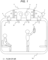
- FIG. 1 is a cross-sectional view of a railway vehicle to which a railway vehicle air-conditioning apparatus can be mounted, and particularly illustrates arrangement of main components in an example in which a vehicle air-conditioning apparatus 1 is installed on the side of a ceiling of a vehicle body 101.
- air inside the vehicle flows into the vehicle air-conditioning apparatus 1 on the ceiling via grilles 51 as indicated by arrows in the drawing. This air further passes through respective filters 5, and passes through respective vehicle-indoor-side heat exchangers 3.
- the air enters indoor-side fans 4, and by pressure increase at the indoor-side fans 4, the air is returned to the side of the vehicle interior via the grilles 51.
- a refrigerant having a temperature lower than an indoor air temperature is supplied to the heat exchanger 3, to decrease the temperature of the air passing through the heat exchanger 3. At this time, water vapor in the air may be subjected to dew condensation on the surface of the heat exchanger 3 to form liquid droplets or a liquid film.
- a refrigerant having a temperature higher than an indoor air temperature is supplied to the heat exchanger 3, to increase the temperature of the air passing through the heat exchanger 3.
- the air blown out (generated) by the indoor-side fans 4 is distributed entirely into the vehicle body 101 via a duct, and thus a fan of a high static pressure type is often used, and for example, a centrifugal fan, a sirocco fan, or the like is suitably used.
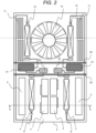
- FIG. 2 is a cross-sectional arrangement view of the railway vehicle air-conditioning apparatus as viewed from above.
- the vehicle air-conditioning apparatus 1 is mainly divided into two blocks. Specifically, in FIG. 2 , compressors 21 and accumulators 22 are placed between partition plates 52, and an upper side of FIG. 2 with respect to the partition plate 52 is a block of a duct in which outdoor air is handled, and a lower side of FIG. 2 with respect to the partition plate 52 is a block of a duct in which indoor air is handled as described in FIG. 1 .
- the cross section taken along line A-A' in FIG. 2 corresponds to FIG. 1 .
- the filters 5, the vehicle-indoor-side heat exchangers 3, and the indoor-side fans 4 are disposed inside a casing.
- the air inside the vehicle flows from the far side to the near side of the plane of the paper of FIG. 2 via the filters 5.
- the air flowing from the left and right filters 5 passes through the indoor-side heat exchangers 3 on the central side, and is further returned to the inside of the vehicle by the indoor-side fans 4 disposed at the center.
- the compressors 21 and the accumulators 22 are disposed at the center of FIG. 2 .
- the compressor 21 compresses a refrigerant on the suction side to increase the pressure of the refrigerant, and delivers the refrigerant.
- the accumulator 22 prevents return of a large amount of liquid refrigerant to the compressor 21.
- outdoor-side heat exchangers 12 and an outdoor-side fan 13 are disposed inside a casing. Air outside the vehicle is introduced from outdoor air intake ports 11 each of which is formed by a part of the casing being opened, and the air passes through the outdoor-side heat exchangers 12, and is blown out again to the outside of the vehicle through the outdoor-side fan 13.
- a refrigerant gas whose pressure is increased by the compressor 21 flows to the outdoor-side heat exchanger 12, and the refrigerant condensed and liquefied here flows to a distributor 6 of the indoor-side heat exchanger 3, where the refrigerant flows through a plurality of paths branched therefrom to be decompressed and flows to the indoor-side heat exchanger 3. Then, the refrigerant evaporated in the indoor-side heat exchanger 3 returns to the compressor 21 via the accumulator 22.
- the refrigerant pipe is connected to realize this flow of the refrigerant.
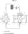
- FIG. 3 is a cycle system diagram according to the railway vehicle air-conditioning apparatus of this first embodiment. Note that the invention is not limited by the following embodiments.
- the flow of air and the flow of refrigerant are respectively similar to those in the vehicle air-conditioning apparatus illustrated in FIGS. 1 and 2 .
- Regarding the flow of air on the indoor side, air from the inside of the vehicle passes through the filter 5, passes through the vehicle-indoor-side heat exchanger 3, and returns to the inside of the vehicle again through the indoor-side fan 4.
- air outside the vehicle passes through the outdoor-side heat exchanger 12 and is released to the outside of the vehicle again through the outdoor-side fan 13.
- a duct 2 is schematically illustrated to be seemingly present only on the indoor side, but actually the duct 2 is also present on the outdoor side.
- the indoor-side fan 4 is illustrated to be shaped like an axial fan, but a fan of a high static pressure type called a centrifugal fan or a sirocco fan is suitably used for the indoor-side fan 4.
- the vehicle air-conditioning apparatus is dedicated to a cooling operation.
- the indoor-side heat exchanger 3 is always used as an evaporator, and the outdoor-side heat exchanger 12 is always used as a condenser.
- a high-temperature and high-pressure gas refrigerant discharged from the compressor 21 flows to the outdoor-side heat exchanger 12 via an outdoor-side heat exchanger gas header 14.
- a liquid refrigerant condensed here passes through the distributor 6 and further passes through capillary tubes 7 to be decompressed to become a low-temperature and low-pressure refrigerant and to be partially gasified, which then flows to the indoor-side heat exchanger 3.
- the refrigerant evaporated and substantially gasified here flows to the accumulator 22 via an indoor-side heat exchanger gas header 8, and is sucked again into the compressor 21.
- an indoor-side heat exchanger suction air sensor 31 is disposed upstream of the indoor-side heat exchanger 3 in the air flow direction in the duct 2, and an indoor-side heat exchanger discharge air sensor 32 is disposed downstream of the indoor-side heat exchanger 3.
- a temperature and humidity of air before being subjected to temperature adjustment through the indoor-side heat exchanger 3 can be measured by the indoor-side heat exchanger suction air sensor (first sensor) 31.
- a temperature and, in some cases, humidity of air after being subjected to temperature adjustment through the indoor-side heat exchanger 3 can be measured by the indoor-side heat exchanger discharge air sensor 32.
- a temperature on the refrigerant inflow side of the indoor-side heat exchanger 3 can be measured by an indoor-side heat exchanger refrigerant inlet sensor (third sensor) 33.
- the indoor-side heat exchanger refrigerant inlet sensor 33 may directly measure a refrigerant temperature.
- the indoor-side heat exchanger refrigerant inlet sensor 33 may measure a pipe surface temperature of the indoor-side heat exchanger 3, and may be, in some cases, attached to the surface of a distribution pipe such as the capillary tube 7 that guides the refrigerant to the pipe of the indoor-side heat exchanger 3.
- an outdoor-side heat exchanger suction air sensor (second sensor) 36 is disposed upstream of the outdoor-side heat exchanger 12 in the flow direction, and an outdoor-side heat exchanger discharge air sensor 37 is disposed downstream of the outdoor-side heat exchanger 12.
- a temperature (corresponding to an outdoor temperature) and humidity of air before passing through the outdoor-side heat exchanger 12 can be measured by the outdoor-side heat exchanger suction air sensor 36, and a temperature and humidity of air after passing through the outdoor-side heat exchanger 12 can be measured by the outdoor-side heat exchanger discharge air sensor 37.
- a temperature of a refrigerant on a side corresponding to an outlet side when the outdoor-side heat exchanger 12 is used for cooling can be measured by an outdoor-side heat exchanger refrigerant inlet sensor 38.
- the outdoor-side heat exchanger refrigerant inlet sensor 38 may measure a pipe surface temperature of the outdoor-side heat exchanger 12 instead of the refrigerant temperature, and may be, in some cases, attached to the surface of a distribution pipe of the outdoor-side heat exchanger 12.
- a temperature of a refrigerant to be measured by the outdoor-side heat exchanger refrigerant inlet sensor (fourth sensor) 38 is a temperature of a refrigerant cooled and liquefied in the outdoor-side heat exchanger 12, and thus a temperature of a pipe after the distribution pipes of the outdoor-side heat exchanger 12 are merged can be measured and used as a substitute.
- the pipe is limited to a pipe through which a refrigerant before passing through a large decompression element, such as an expansion valve or a capillary tube, passes.
- an air-conditioning control device obtains a decrease in an airflow rate.
- an airflow rate feature R can be obtained by Formula (1) described below using constants C1 to C4 obtained by learning from data of several days to several weeks immediately after cleaning during which there is determined to be no dust on the heat exchanger and the filter.
- R [Teva] + C1 ⁇ [Ta-in] + C2 ⁇ [Rha - in] + C3 ⁇ [To-in] + C4 ⁇ [Tsc]
- a threshold (first threshold) ⁇ 1 at which the air-conditioning control device can determine, based on the long-term learning, that an airflow rate decreases is obtained in advance, and the decrease in the airflow rate is determined in a case where the airflow rate feature R decreases below the threshold ⁇ 1.
- the airflow rate feature R described here is an example, and it is possible to form the airflow rate feature R more resistant to disturbance by further using the sensors described above or by changing Formula (1), which is a feature calculation formula, and a coefficient learning method thereof.
- the learning of the constant and the threshold may be created through data obtained by a trial operation or simulation as well as an actual operation.
- an indoor-side heat exchanger differential pressure sensor (fifth sensor) 34 that measures a pressure difference of air between an inlet and an outlet of the indoor-side heat exchanger 3 is added in the duct 2.
- pressure loss in the flow of air passing through the indoor-side heat exchanger 3 can be measured. This pressure loss increases as an airflow rate increases, and decreases as the airflow rate decreases, if the indoor-side heat exchanger 3 is free of contamination and the surface of the indoor-side heat exchanger 3 is not subjected to dew condensation.
- FIG. 4 is a schematic diagram illustrating an extracted configuration on the indoor side in the railway vehicle air-conditioning apparatus according to the present embodiment.
- FIG. 4 particularly illustrates a state in which dust 61 is deposited only on the filter 5.
- air is caused to flow in an air blowing mode in which no dew condensation occurs on the surface of the heat exchanger, and a change in the airflow rate can be grasped from a change in pressure loss across the indoor-side heat exchanger differential pressure sensor 34.
- the factor that causes the decrease in the airflow rate can be determined to be the dust 61 on the filter 5.
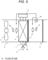
- FIG. 5 is a schematic diagram illustrating an extracted configuration on the indoor side in the railway vehicle air-conditioning apparatus according to the present embodiment.
- FIG. 5 particularly illustrates a case in which the dust 61 is deposited only on the indoor-side heat exchanger 3. At this time, an airflow rate of air flowing on the indoor side is lower than the airflow rate in a case where there is no dust 61.
- the dust 61 is deposited on the windward side of the indoor-side heat exchanger 3 and this may lead to an increase in pressure loss, and thus it is conceivable that the pressure loss across the indoor-side heat exchanger differential pressure sensor 34 does not change.
- differential pressure sensors are provided in front of and behind the filter 5, a decrease in an airflow rate can be detected from a change in pressure loss in this side.
- the filter 5 is often designed to be replaceable from the vehicle interior side, separately from the air-conditioning apparatus.
- additional wiring is required to exchange information between the differently designed sensors and air-conditioning apparatus.
- the differential pressure sensor itself is not inexpensive, and thus it is desirable to reduce the number of sensors as much as possible.
- FIG. 6 is a schematic diagram illustrating an extracted configuration on the indoor side in the railway vehicle air-conditioning apparatus according to the present embodiment.
- FIG. 6 illustrates a case in which the dust 61 is deposited on both the indoor-side heat exchanger 3 and the filter 5. In actual operation, it is typically considered that dust is accumulated simultaneously on both the indoor-side heat exchanger 3 and the filter 5 like this case.
- the differential pressure sensors are provided in front of and behind the filter 5 though not illustrated as described in the description of FIG. 5 , it is possible to detect the decrease in the airflow rate by totaling with the pressure loss across the indoor-side heat exchanger differential pressure sensor 34 and from a pressure-airflow rate characteristic curve of the indoor-side fan 4.
- the filter 5 is disposed on the upstream side of the indoor-side heat exchanger 3, and fine dust that cannot be captured by the filter 5 flows to the indoor-side heat exchanger 3.
- a fin-tube type heat exchanger is used in which a fin tube is formed of a metal pipe through which a refrigerant flows and metal fins having a plate shape attached to the surface of the metal pipe.
- the air-conditioning apparatus is particularly dedicated to the cooling operation, and the indoor-side heat exchanger 3 is used as an evaporator.
- the indoor-side heat exchanger 3 is used as an evaporator.
- FIG. 7 illustrates flows of processing for identifying an amount of dust deposited in the air-conditioning apparatus, particularly respective amounts of dust deposited on the indoor-side heat exchanger 3 and the filter 5, under such conditions. Determination in the following flows is performed by an air-conditioning control device (cleaning time diagnosis device) (not illustrated) that receives output of each sensor and performs calculation, and that stores the threshold ⁇ 1 and the like in a memory built therein.
- an air-conditioning control device cleaning time diagnosis device
- the air-conditioning control device calculates the airflow rate feature R from Formula (1) in step S02, and then compares the airflow rate feature R with the threshold ⁇ 1 in step S03.
- the airflow rate feature R is used to determine whether the airflow rate feature R is smaller than the known threshold ⁇ 1, on the premise that a smaller airflow rate feature R indicates a more decrease in the airflow rate.
- the air-conditioning control device determines that the decrease in the airflow rate does not occur, and recognizes this result as normal in which the operation can be continued, to proceed with the processing.
- step S04 for example, the air-conditioning control device causes a display (not illustrated) to display information indicating that the filter 5 and the indoor-side heat exchanger 3 are normal (there is no need of cleaning because dust does not adhere).
- the processing further returns to step S02 to continue the cooling operation.
- the air-conditioning control device determines that there is a possibility that dust whose amount falls outside the acceptable range adheres to at least one of the filter 5 or the indoor-side heat exchanger 3 due to the decrease in the airflow rate, and causes the flow to proceed to step S06.
- the air-conditioning control device estimates a value Q2 of the decreased airflow rate from the airflow rate feature R, and obtains total reference pressure loss at the filter 5 and the indoor-side heat exchanger 3 caused along with passage of air through the filter 5 and the indoor-side heat exchanger 3 when a normal operation is performed in a state where there is no dust at the decreased airflow rate Q2.
- the total reference pressure loss may be obtained by calculating an air-blowing resistance coefficient from a design specification, or may be obtained by calculating a resistance coefficient at a normal airflow rate from data obtained during a period of time in which normality is maintained, that is, during a period in which there is no deposition of dust.
- a reference pressure loss at the indoor-side heat exchanger 3 needs to be calculated in consideration of dew condensation.
- an amount of condensed water is estimated by using the temperature and humidity of the air on the upstream side of the heat exchanger detected by the indoor-side heat exchanger suction air sensor 31 and the evaporation temperature of the refrigerant in the indoor-side heat exchanger 3 detected by the indoor-side heat exchanger refrigerant inlet sensor 33.
- the reference pressure loss at the indoor-side heat exchanger may be calculated by using an amount of dew condensation, which may be calculated from changes in temperature and humidity between the indoor-side heat exchanger suction air sensor 31 and the indoor-side heat exchanger discharge air sensor 32.
- the air-conditioning control device obtains a difference between this calculated reference pressure loss P HEX_CAL at the indoor-side heat exchanger 3, which considers the influence of dew condensation, and a measured differential pressure P HEX_EXP obtained by the indoor-side heat exchanger differential pressure sensor 34.
- the reference pressure loss P HEX_CAL and the measured differential pressure P HEX_EXP are substantially the same, it indicates that the pressure loss caused due to the passage of air through the indoor-side heat exchanger 3 can be estimated while assuming a substantially dust-free state, and this indicates that no dust is present on the indoor-side heat exchanger 3 or dust whose amount is enough to be detected is not accumulated thereon.
- a heat exchanger differential pressure ⁇ P HEX is calculated that is a difference between the calculation value (reference pressure loss P HEX_CAL ) and the measured value (measured differential pressure P HEX_EXP ) of the pressure loss at the indoor-side heat exchanger 3.
- the air-conditioning control device estimates a fan pressure P FAN_2 corresponding to the decreased airflow rate Q2 from the decreased airflow rate Q2 and a [pressure-airflow rate characteristic curve] of the indoor-side fan 4. If an airflow rate decreases, the pressure increases in most cases.
- a value obtained by subtracting the measured differential pressure P HEX_EXP at the indoor-side heat exchanger 3 and the loss at the air blowing system other than the filter 5 from the fan pressure P FAN_2 is a differential pressure generated across the indoor-side fan 4. If this differential pressure is the same as the filter pressure loss P filter obtained when there is no dust, which has been calculated above, it can be determined that the filter 5 is free of dust or has only undetectable little dust.
- the air-conditioning control device calculates a total differential pressure ⁇ P Total obtained by subtracting the pressure loss P HEX_CAL at the indoor-side heat exchanger 3 and the filter pressure loss P filter , which are obtained when there is no dust, from the fan pressure P FAN_2 corresponding to the increased pressure at the fan obtained when the decrease in the airflow rate to Q2 occurs.
- the air-conditioning control device determines initially in step S07 whether there is dust on the indoor-side heat exchanger 3 by comparing the heat exchanger differential pressure ⁇ P HEX with a threshold (second threshold) ⁇ 1 as to whether the heat exchanger differential pressure ⁇ P HEX is smaller than the threshold ⁇ 1.
- the heat exchanger differential pressure ⁇ P HEX is the difference between the pressure loss obtained when there is no dust and the measured value.
- the heat exchanger differential pressure ⁇ P HEX is smaller than the threshold ⁇ 1
- the calculation value (reference pressure loss) obtained when there is no dust corresponds to the measured pressure loss at the indoor-side heat exchanger 3, that is, this case indicates that the indoor-side heat exchanger 3 has almost no dust (the amount of adhering dust falls within the acceptable range).
- the heat exchanger differential pressure ⁇ P HEX is equal to or greater than the threshold ⁇ 1
- the air-conditioning control device determines in step S08 whether the factor that causes the decrease in the airflow rate is based on only dew condensation.
- the total differential pressure ⁇ P Total described above is obtained by subtracting the total reference pressure loss at the indoor-side heat exchanger 3 and the filter 5, which is the pressure loss in the case where there is no dust, from the static pressure at the indoor-side fan 4 corresponding to the decreased airflow rate Q2.
- the air-conditioning control device determines that neither the indoor-side heat exchanger 3 nor the filter 5 is subjected to accumulation of dust, and that the indoor-side heat exchanger 3 and the filter 5 are normal, and causes the flow to proceed to step S04.
- the air-conditioning control device determines that a factor that causes the increase in pressure loss, that is, accumulation of dust, is present in the filter 5, which is the remaining location for the factor. Then, in step S09, the air-conditioning control device causes the display (not illustrated) to display information indicating that cleaning of the filter 5 is necessary because dust adheres to the filter 5, and subsequently causes the flow to proceed to step S05.
- step S10 the air-conditioning control device checks whether a value (filter differential pressure) obtained by subtracting the value of the heat exchanger differential pressure ⁇ P HEX from the value of the total differential pressure ⁇ P Total , described above, is smaller than a threshold (fourth threshold) ⁇ 3.
- the air-conditioning control device causes the display (not illustrated) to display information indicating that cleaning of the indoor-side heat exchanger 3 is necessary because dust adheres to the indoor-side heat exchanger 3, and subsequently causes the flow to proceed to step S05.
- the air-conditioning control device causes the display (not illustrated) to display information indicating that cleaning of the indoor-side heat exchanger 3 and the filter 5 is necessary because dust adheres to the indoor-side heat exchanger 3 and the filter 5, and then causes the flow to proceed to step S05.
- the thresholds ⁇ 1 to ⁇ 3 are values in consideration of a pressure loss other than those at the filter 5 and the indoor-side heat exchanger 3, and these values are also determined from data when the filter 5 and the indoor-side heat exchanger 3 are not contaminated. This data may be data during business operation or other data.
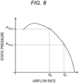
- FIG. 8 is a graph illustrating an example of a characteristic curve of the indoor-side fan 4 used in the first embodiment of the invention, where the vertical axis represents static pressure and the horizontal axis represents airflow rate.
- the airflow rate of the indoor-side fan 4 at the time when there is no dust on the filter 5 and the indoor-side heat exchanger 3 is Q1
- the fan exhibits a static pressure P FAN_1
- this static pressure and air sucked in from the inside of the vehicle are equal to air-blowing resistance of the entire air-conditioning apparatus obtained by being totaled until this static pressure and the air sucked in from the inside of the vehicle return to the inside of the vehicle again via the filter 5, the indoor-side heat exchanger 3, and the indoor-side fan 4.
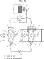
- FIGS. 9 and 10 are cycle system diagrams according to a railway vehicle air-conditioning apparatus of this second embodiment.
- the flow of air is similar to that in the vehicle air-conditioning apparatus illustrated in FIGS. 1 and 2 .
- air from the inside of the vehicle passes through the filter 5, passes through the indoor-side heat exchanger 3, and returns to the inside of the vehicle again through the indoor-side fan 4.
- air outside the vehicle passes through the outdoor-side heat exchanger 12 via an outdoor filter (not illustrated), and is released to the outside of the vehicle again through the outdoor-side fan 13.
- the duct 2 is schematically illustrated to be seemingly present only on the indoor side, but actually the duct 2 is also present on the outdoor side.
- the indoor-side fan 4 is illustrated to be shaped like an axial fan, but a fan of a high static pressure type called a centrifugal fan or a sirocco fan is suitably used for the indoor-side fan 4.
- FIG. 9 illustrates the flow of the refrigerant during the cooling in which the indoor-side heat exchanger 3 is used as an evaporator
- FIG. 10 illustrates the flow of the refrigerant during the heating in which the indoor-side heat exchanger 3 is used as a condenser.
- a high-temperature gas refrigerant discharged from the compressor 21 passes through the four-way valve 23 and flows through the outdoor-side heat exchanger gas header 14 to the outdoor-side heat exchanger 12, where the refrigerant is cooled and liquefied by the outside air.
- the liquefied refrigerant flows through an outdoor-side distributor 15 to an expansion valve 24, and is decompressed in the expansion valve 24, whereby part of the liquid refrigerant is gasified and the temperature of the refrigerant decreases.
- the refrigerant that has been decompressed and whose temperature has decreased in the expansion valve 24 reaches the indoor-side heat exchanger 3 from the distributor 6 via the capillary tubes 7.
- the capillary tube 7 is used here to cause the refrigerant distributed by the distributor 6 to flow into the refrigerant path in the indoor-side heat exchanger 3.
- the capillary tube 7 it is not necessary to decrease the refrigerant pressure, that is, it is not necessary to decompress the refrigerant.
- the refrigerant evaporated and gasified by cooling vehicle interior air in the indoor-side heat exchanger 3 reaches the four-way valve 23 via the indoor-side heat exchanger gas header 8, and then returns to the compressor 21 via the accumulator 22.
- the low-temperature and low-pressure gas refrigerant is sucked into the compressor 21, is compressed and increased in pressure to become a high-temperature and high-pressure gas refrigerant, and is discharged. Then, the refrigerant flows again to the four-way valve 23.
- a high-temperature gas refrigerant discharged from the compressor 21 passes through the four-way valve 23, flows toward the indoor-side heat exchanger gas header 8, and flows to the indoor-side heat exchanger 3, where the refrigerant itself is cooled and liquefied by heating vehicle interior air.
- the liquefied refrigerant flows through the capillary tubes 7 and further flows from the distributor 6 to the expansion valve 24, and is decompressed in the expansion valve 24, whereby part of the liquid refrigerant is gasified and the temperature of the refrigerant further decreases.
- the refrigerant that has been decompressed and whose temperature has decreased in the expansion valve 24 reaches the outdoor-side heat exchanger 12 via the outdoor-side distributor 15.
- the low-temperature and low-pressure gas refrigerant is sucked into the compressor 21, is compressed and increased in pressure to become a high-temperature and high-pressure gas refrigerant, and is discharged. Then, the refrigerant flows again to the four-way valve 23.
- an indoor-side heat exchanger suction air sensor (seventh sensor) 31 is provided on the suction side, where air from the inside of the vehicle is sucked in, in the indoor-side casing to measure an air temperature and humidity of air before being subjected to temperature adjustment through the indoor-side heat exchanger 3.
- an air temperature after being subjected to temperature adjustment through the indoor-side heat exchanger 3 is measured by the indoor-side heat exchanger discharge air sensor 32.
- the humidity may also be measured by the indoor-side heat exchanger discharge air sensor 32.
- an indoor-side heat exchanger refrigerant inlet sensor (ninth sensor) 33 is provided at the capillary tube 7 to measure a refrigerant temperature after the refrigerant has passed through the distributor 6 during the cooling.
- the evaporation temperature is basically a temperature obtained by measuring the saturation temperature of the refrigerant inside the indoor-side heat exchanger 3.
- the refrigerant may become a superheated gas refrigerant to have a temperature higher than the saturation temperature.
- the temperature sensor is attached to the capillary tube 7 corresponding to the inlet of the heat exchanger.
- a sensor for measuring a pressure of the refrigerant may be provided in the vicinity of the indoor-side heat exchanger 3, but there is a problem that the cost increases.
- an outdoor-side heat exchanger suction air sensor (sixth sensor) 36 is provided on the suction side where air outside the vehicle is sucked in to measure an air temperature and humidity of air before being subjected to temperature adjustment through the outdoor-side heat exchanger 12.
- an air temperature of air after being subjected to temperature adjustment through the outdoor-side heat exchanger 12 is measured by the outdoor-side heat exchanger discharge air sensor 37.
- the humidity may also be measured by the outdoor-side heat exchanger discharge air sensor 37.
- an outdoor-side heat exchanger refrigerant inlet sensor (eighth sensor) 38 is provided to measure a refrigerant temperature after the refrigerant has passed through the outdoor-side distributor 15 during the heating.
- the evaporation temperature is basically a temperature obtained by measuring the saturation temperature of the refrigerant inside the outdoor-side heat exchanger 12.
- the refrigerant may become a superheated gas refrigerant to have a temperature higher than the saturation temperature.
- the temperature sensor is attached at a location corresponding to the inlet of the heat exchanger.
- a sensor for measuring a pressure of the refrigerant may be provided in the vicinity of the outdoor-side heat exchanger 12.
- a compressor suction-side refrigerant sensor 35 is provided to measure the refrigerant pressure and a temperature on the suction side of the compressor.
- the change in air pressure caused along with the air blowing across the indoor-side heat exchanger 3 is measured by the indoor-side heat exchanger differential pressure sensor 34.
- the air-conditioning control device can similarly detect accumulation of dust deposited on the indoor-side heat exchanger 3 and the filter 5 during the cooling, with the processing in the flows illustrated in FIG. 7 .
- the air-conditioning control device receives, as input, signals from the sixth to ninth sensors, obtains an airflow rate feature (R) based on information (Teva) on a temperature of a refrigerant flowing into the outdoor-side heat exchanger 12, information (Ta-in) on an air temperature upstream of the outdoor-side heat exchanger 12, information (RHa-in) on humidity upstream of the outdoor-side heat exchanger 12, information (To-in) on an air temperature upstream of the indoor-side heat exchanger 3, and information (Tsc) on a temperature of a refrigerant flowing out of the indoor-side heat exchanger 3, and determines that there is a possibility that dust adheres to at least one of the outdoor filter or the outdoor-side heat exchanger 12 in a case where the air-conditioning control device determines that the airflow rate feature (R) is smaller than a fifth threshold ( ⁇ 2).
- the fifth threshold ( ⁇ 2) can be obtained in a manner similar to the manner for obtaining the first threshold ( ⁇ 1).
- the air-conditioning control device can similarly determine whether dust is deposited on the outdoor filter or the outdoor-side heat exchanger 12 in accordance with the flows of FIG. 7 .
- the air-conditioning control device can also cause the display to display information on whether dust is deposited on the outdoor filter or the outdoor-side heat exchanger 12.
- the outdoor-side heat exchanger 12 during the cooling is used as a condenser, and thus dew condensation does not occur on the surface of the outdoor-side heat exchanger 12.
- a type of filter on which dust can be deposited is not provided, it is not necessary to distinguish dust depositions between the filter and the heat exchanger, and therefore, when a decrease in an airflow rate at the outdoor-side heat exchanger 12 can be detected from the measured temperature, humidity, and pressure data, an increase in pressure loss caused due to the deposition of dust or powder dust such as dirt, which may be present due to the fact of being on the outdoor side, on the outdoor-side heat exchanger 12 can be easily estimated as a factor that causes the decrease in the airflow rate.
- the decrease in the airflow rate may be detected by using the compressor suction-side refrigerant sensor 35, the outdoor-side heat exchanger refrigerant inlet sensor 38, the outdoor-side heat exchanger suction air sensor 36, and the outdoor-side heat exchanger discharge air sensor 37 to perform learning based on data during a normal operation such as an operation after cleaning.
- a normal operation such as an operation after cleaning.
- the detection of the decrease in the airflow rate is not limited to the above means because various means for obtaining the enthalpy illustrated in the embodiment can be considered.
- the indoor-side heat exchanger 3 is used as a condenser, and thus dew condensation does not occur on the indoor-side heat exchanger 3.
- dew condensation does not occur on the indoor-side heat exchanger 3.
- the outdoor-side heat exchanger 12 may be subjected to dew condensation or frost formation during the heating.
- the humidity of air sucked into the outdoor-side heat exchanger 12 is grasped by the outdoor-side heat exchanger suction air sensor 36, and the evaporation temperature is grasped by the outdoor-side heat exchanger refrigerant inlet sensor 38, whereby an amount of the dew condensation is estimated, to enable estimating an increase in pressure loss.
- frost has been formed, it is difficult to estimate the pressure loss.
- the evaporation temperature obtained by the outdoor-side heat exchanger refrigerant inlet sensor 38 is, for example, 0°C or lower, it is conceivable to add processing of skipping the determination.
- the evaporation temperature for determining the frost formation needs to be adjusted depending on vehicles, operation conditions, and the like.
- FIG. 11 is a cross-sectional view illustrating arrangement of a railway vehicle air-conditioning apparatus according to this third embodiment.
- each heat exchanger suction-side illuminance sensor (first light sensor) 39 is provided between the filter 5 and the indoor-side heat exchanger 3
- each heat exchanger blowing-out-side illuminance sensor (second light sensor) 40 is provided between the indoor-side heat exchanger 3 and the indoor-side fan 4.
- Each illuminance sensor is a sensor that measures illuminance, brightness, and the like of light reaching the sensor after having been emitted from a corresponding one of vehicle interior lighting devices 9, installed inside the vehicle body 101, that is, in the inside of the vehicle, and having passed through or being transmitted through the grille 51, the filter 5, and/or the indoor-side heat exchanger 3.
- the amount of light detected by the heat exchanger suction-side illuminance sensor 39 is presumed to decrease, when dust is deposited on the filter 5, in accordance with the amount of the dust.
- the amount of light detected by the heat exchanger blowing-out-side illuminance sensor 40 is presumed to further decrease because the amount of the light having reached the heat exchanger suction-side illuminance sensor 39 is further decreased by dust deposited on the indoor-side heat exchanger 3.
- These detection values of the sensors are subjected to influences of brightness outside the vehicle, sensor positions, and states of the vehicle interior lighting devices 9.
- the influence of brightness outside the vehicle is decreased by limiting a timing of measurement to, for example, a night time after business operation.
- the influence of variation or the like, for each vehicle body, in the sensor position or the state of the vehicle interior lighting device 9 can be decreased by learning data particularly at a time when there is no dust such as a time after cleaning and by calibrating it.
- LEDs light-emitting diodes
- an effect of decreasing the influence may be further obtained by measuring a temperature of air inside the vehicle and adding this value to the element of the learning.
- a rail vehicle air-conditioning apparatus including:
- the rail vehicle air-conditioning apparatus further including:
- the rail vehicle air-conditioning apparatus according to a third aspect, in which the air-conditioning control device is configured to:
- the rail vehicle air-conditioning apparatus in which the air-conditioning control device is configured to:
- an air-conditioning apparatus for a railway vehicle in which
- the air-conditioning control device is configured to cause a display to display information on whether at least one of an amount of dust adhering to the indoor-side heat exchanger or the outdoor-side heat exchanger and an amount of dust adhering to the filter or the outdoor filter falls within an acceptable range.
Landscapes
- Engineering & Computer Science (AREA)
- Mechanical Engineering (AREA)
- Physics & Mathematics (AREA)
- Thermal Sciences (AREA)
- Filtering Of Dispersed Particles In Gases (AREA)
Applications Claiming Priority (1)
| Application Number | Priority Date | Filing Date | Title |
|---|---|---|---|
| JP2023097453A JP2024178989A (ja) | 2023-06-14 | 2023-06-14 | 軌条車両用空気調和装置 |
Publications (1)
| Publication Number | Publication Date |
|---|---|
| EP4477491A1 true EP4477491A1 (fr) | 2024-12-18 |
Family
ID=91431407
Family Applications (1)
| Application Number | Title | Priority Date | Filing Date |
|---|---|---|---|
| EP24180327.9A Pending EP4477491A1 (fr) | 2023-06-14 | 2024-06-05 | Appareil de climatisation de véhicule ferroviaire |
Country Status (2)
| Country | Link |
|---|---|
| EP (1) | EP4477491A1 (fr) |
| JP (1) | JP2024178989A (fr) |
Cited By (1)
| Publication number | Priority date | Publication date | Assignee | Title |
|---|---|---|---|---|
| US20240010051A1 (en) * | 2021-06-24 | 2024-01-11 | Hitachi, Ltd. | Air conditioner for rail vehicle |
Citations (4)
| Publication number | Priority date | Publication date | Assignee | Title |
|---|---|---|---|---|
| JP2012126351A (ja) * | 2010-12-17 | 2012-07-05 | Mitsubishi Electric Corp | 磁気フィルタを使用した車両用空気調和装置及び磁気フィルタ |
| WO2012168971A1 (fr) * | 2011-06-08 | 2012-12-13 | 三菱電機株式会社 | Dispositif de réfrigération/conditionnement d'air |
| JP2016124461A (ja) * | 2015-01-06 | 2016-07-11 | 株式会社東芝 | 車両用熱交換装置およびフィルタ |
| US20190137199A1 (en) * | 2016-06-10 | 2019-05-09 | Mitsubishi Electric Corporation | Vehicle air-conditioning apparatus and clogging detection system for vehicle air-conditioning apparatus |
-
2023
- 2023-06-14 JP JP2023097453A patent/JP2024178989A/ja active Pending
-
2024
- 2024-06-05 EP EP24180327.9A patent/EP4477491A1/fr active Pending
Patent Citations (4)
| Publication number | Priority date | Publication date | Assignee | Title |
|---|---|---|---|---|
| JP2012126351A (ja) * | 2010-12-17 | 2012-07-05 | Mitsubishi Electric Corp | 磁気フィルタを使用した車両用空気調和装置及び磁気フィルタ |
| WO2012168971A1 (fr) * | 2011-06-08 | 2012-12-13 | 三菱電機株式会社 | Dispositif de réfrigération/conditionnement d'air |
| JP2016124461A (ja) * | 2015-01-06 | 2016-07-11 | 株式会社東芝 | 車両用熱交換装置およびフィルタ |
| US20190137199A1 (en) * | 2016-06-10 | 2019-05-09 | Mitsubishi Electric Corporation | Vehicle air-conditioning apparatus and clogging detection system for vehicle air-conditioning apparatus |
Cited By (2)
| Publication number | Priority date | Publication date | Assignee | Title |
|---|---|---|---|---|
| US20240010051A1 (en) * | 2021-06-24 | 2024-01-11 | Hitachi, Ltd. | Air conditioner for rail vehicle |
| US12415406B2 (en) * | 2021-06-24 | 2025-09-16 | Hitachi, Ltd. | Air conditioner for rail vehicle |
Also Published As
| Publication number | Publication date |
|---|---|
| JP2024178989A (ja) | 2024-12-26 |
Similar Documents
| Publication | Publication Date | Title |
|---|---|---|
| US7494536B2 (en) | Method for detecting a fault in an HVAC system | |
| JP5787604B2 (ja) | 車両用空気調和装置故障診断システム及び故障診断装置 | |
| CN100529717C (zh) | 用于检测热交换器的异常的方法和装置以及该装置的使用 | |
| KR102436213B1 (ko) | 공조 관리 시스템, 공조 관리 방법, 및 프로그램 | |
| EP2354724B1 (fr) | Climatiseur d'air et son procédé de commande | |
| CN105065249B (zh) | 压缩机性能检测装置、具有该装置的空调系统和控制方法 | |
| US20120180506A1 (en) | Refrigeration and air-conditioning apparatus | |
| US20180340719A1 (en) | Detection of lack of refrigerant in a cooling system having multiple cooling locations | |
| Li et al. | Virtual refrigerant pressure sensors for use in monitoring and fault diagnosis of vapor-compression equipment | |
| EP1839021A2 (fr) | Procede et commande permettant de determiner une charge de refrigerant faible | |
| CN105627612B (zh) | 室外机冷媒管路系统、空调器及空调器的制冷控制方法 | |
| EP4477491A1 (fr) | Appareil de climatisation de véhicule ferroviaire | |
| US7219506B2 (en) | Method for estimating inlet and outlet air conditions of an HVAC system | |
| JP4532454B2 (ja) | 空気調和機 | |
| CN106839301A (zh) | 空调器除霜逻辑控制方法及装置 | |
| US9416999B2 (en) | Method for determining wire connections in a vapour compression system | |
| CN108463679A (zh) | 一种用于在应急模式下控制到蒸发器的制冷剂供应的方法 | |
| JP7445533B2 (ja) | 異常検出装置、プログラムおよび電気機器システム | |
| CN102967450B (zh) | 多联式空调机组的外机单向阀是否装反的检测方法 | |
| CN112097364A (zh) | 空调器及其电子膨胀阀故障检测方法 | |
| JP2011149646A (ja) | 空気調和機 | |
| CN216557574U (zh) | 多内机管路感温包空调器 | |
| KR20090067738A (ko) | 공기조화기의 제어방법 | |
| JP4004356B2 (ja) | 圧縮機の油面検出方法及び装置 | |
| CN116734391B (zh) | 空调系统及其检测方法以及空调器 |
Legal Events
| Date | Code | Title | Description |
|---|---|---|---|
| PUAI | Public reference made under article 153(3) epc to a published international application that has entered the european phase |
Free format text: ORIGINAL CODE: 0009012 |
|
| STAA | Information on the status of an ep patent application or granted ep patent |
Free format text: STATUS: REQUEST FOR EXAMINATION WAS MADE |
|
| 17P | Request for examination filed |
Effective date: 20240605 |
|
| AK | Designated contracting states |
Kind code of ref document: A1 Designated state(s): AL AT BE BG CH CY CZ DE DK EE ES FI FR GB GR HR HU IE IS IT LI LT LU LV MC ME MK MT NL NO PL PT RO RS SE SI SK SM TR |
|
| GRAP | Despatch of communication of intention to grant a patent |
Free format text: ORIGINAL CODE: EPIDOSNIGR1 |
|
| STAA | Information on the status of an ep patent application or granted ep patent |
Free format text: STATUS: GRANT OF PATENT IS INTENDED |
|
| INTG | Intention to grant announced |
Effective date: 20260303 |