EP4477504A1 - Dispositif de plan de charge, carrosserie de véhicule et véhicule - Google Patents
Dispositif de plan de charge, carrosserie de véhicule et véhicule Download PDFInfo
- Publication number
- EP4477504A1 EP4477504A1 EP23179765.5A EP23179765A EP4477504A1 EP 4477504 A1 EP4477504 A1 EP 4477504A1 EP 23179765 A EP23179765 A EP 23179765A EP 4477504 A1 EP4477504 A1 EP 4477504A1
- Authority
- EP
- European Patent Office
- Prior art keywords
- loading level
- loading
- side wall
- pivot axis
- support
- Prior art date
- Legal status (The legal status is an assumption and is not a legal conclusion. Google has not performed a legal analysis and makes no representation as to the accuracy of the status listed.)
- Withdrawn
Links
Images



Classifications
-
- B—PERFORMING OPERATIONS; TRANSPORTING
- B62—LAND VEHICLES FOR TRAVELLING OTHERWISE THAN ON RAILS
- B62D—MOTOR VEHICLES; TRAILERS
- B62D33/00—Superstructures for load-carrying vehicles
- B62D33/04—Enclosed load compartments ; Frameworks for movable panels, tarpaulins or side curtains
- B62D33/042—Enclosed load compartments ; Frameworks for movable panels, tarpaulins or side curtains divided into compartments
Definitions
- the invention relates to a loading level device for a vehicle body.
- the invention further relates to a vehicle body and a vehicle.
- the invention is based on the object of specifying a novel loading level device for a vehicle body, a novel vehicle body and a novel vehicle.
- the loading level device according to the invention for a vehicle body comprises two flat loading level elements which are coupled to one another via a level pivot axis and can be pivoted about this.
- a first of the loading level elements has at least one pivot fastening device at an end facing away from the level pivot axis, by means of which it can be pivoted about a board pivot axis running parallel to the plane pivot axis and to a loading floor of the vehicle body is pivotally attached or can be attached, in particular can be attached or fastened in a non-destructively detachable manner, to a first side wall of the vehicle body.
- a second of the loading level elements has at least one fastening device at an end facing away from the plane pivot axis, by means of which it can be attached, in particular can be attached and/or supported in a non-destructively detachable manner, to a second side wall of the vehicle body opposite the first side wall in a use position.
- the first loading level element pointing upwards from the board pivot axis, rests with an upper side on the first side wall and the second loading level element, pointing downwards from the plane pivot axis, rests with an underside on an underside of the first loading level element or the first side wall.
- the second loading level element is fastened to the second side wall of the vehicle body, in particular fastened and/or supported in a non-destructively detachable manner, and upper sides of both loading level elements run in one plane or in two planes which have a height offset from one another.
- the loading level device is characterized by particularly small dimensions in its stowed position due to the folded state of the loading level elements and can therefore be stored on the first side wall in a space-saving manner.
- the width of the loading space below the loading level device is not affected due to the "folding up" of the two folded loading level elements into an area below the on-board pivot axis and is available across the entire width. A reduction in the width of the loading space is also minimized above the on-board pivot axis, so that maximum loading of the vehicle body is still possible at least almost without restriction.
- the loading level device can be used in a particularly advantageous manner to create a second loading floor, in particular one running plane-parallel to the loading floor, and a further loading level above and at a distance from the loading floor of the vehicle body.
- This makes it possible for, for example, Transport goods can be stored on which no further transport goods can be stacked. Further transport goods can then be stored on the second loading floor so that the height of the loading space can be maximized.
- the loading level device Due to its pivoting structure, the loading level device can be moved between the stowed position and the use position in a particularly simple, safe and reliable manner for a user of the vehicle.
- a side wall is understood to mean both closed solid side walls and interrupted frame-shaped side walls.
- the frame-shaped side walls can be closed or closed with a tarpaulin.
- the first loading level element has a cavity on its underside for at least partially receiving the second loading level element pivoted onto the first loading level element in the stowed position.
- the second loading level element has a cavity on its underside for at least partially receiving the first loading level element pivoted onto the second loading level element in the stowed position.
- this comprises a support element that can be pivoted about a support pivot axis arranged on one of the loading level elements and running in the same direction as the level pivot axis.
- the support element In the stowed position, the support element rests against an underside of the first loading level element, pointing downwards from the support pivot axis, and in the use position is directed downwards from the undersides of the loading level elements for support on the loading floor.
- the support element enables the two loading level elements to be supported on the loading floor and thus the stabilization of the Loading level device in the use position. This in turn results in an increased load-bearing capacity of the loading level device.
- the support element is arranged in the hollow space of the first loading level element and/or in the hollow space of the second loading level element in the stowed position. This enables a particularly space-saving arrangement of the support element without reducing the usable width of the loading space between the side walls in the stowed position.
- the level pivot axis and the support pivot axis coincide in a common axis. This enables the loading level device to be constructed with a support element in a simple manner and with low material and cost expenditure.
- the support pivot axis is positioned such that it is arranged in the middle between the side walls in the use position. This means that the support element runs in the middle between both side walls in the use position. This means that space utilization can be maximized and cargo containers and/or transport pallets of standardized size, for example so-called Euro pallets, can be positioned under the loading floor elements on both sides of the support element.
- the loading level elements each comprise a peripheral frame forming end faces of the loading level elements, wherein a width of the frame of one of the loading level elements running in the direction of the plane pivot axis is smaller than a width of the frame of the other loading level element running in the direction of the plane pivot axis. Furthermore, a length of the frame of one of the loading level elements is also smaller than a length of the frame of the other loading level element, so that end faces of the smaller frame are surrounded by the larger frame in the stowed position.
- Such a design of the loading level elements with a frame enables a particularly stable design of the loading level elements while at the same time requiring little material and space.
- the smaller design of one frame makes it particularly easy to create the cavity for at least partially accommodating one loading level element in the other loading level element in order to minimize the thickness of the loading level device in the stowed position.
- a width of the support element running in the direction of the support pivot axis is smaller than a clear width of the smaller frame. This makes it easy to implement the space-saving arrangement of the support element without reducing the usable width of the loading space between the side walls in the stowed position.
- a flat structure covering at least one free space between the inner sides of the respective frame is arranged between the inner sides of the frame or on an upper side of the frame.
- a storage area for storing transported goods is created on the upper sides of the frame.
- the flat structure comprises a grid, a perforated sheet, a plate and/or several transverse and/or longitudinal struts.
- the upper side of the frame of one of the loading level elements runs in a plane with a lower side of the frame of the other loading level element in the stowed position.
- the support element has a support fastening device for a force-fitting and/or form-fitting fastening to the loading floor. This enables a secure and reliable fixing and/or anchoring of the support element to the loading floor, which results in further stabilization of the loading level device in the use position.
- the support element is coupled to at least one of the loading level elements by means of a guide structure in such a way that the support element is forcibly moved from a stowed position to a supporting position when transferred from the stowed position to the use position, and from the supporting position to the stowed position when transferred from the use position to the stowed position.
- a length of the support element running perpendicular to the support pivot axis is variably adjustable and the support element can be fixed at different lengths.
- this allows the loading level device to be adjusted in height to suit different requirements of different vehicle bodies and can therefore be used universally in different vehicle bodies. It is also possible to carry out a height adjustment in such a way that the loading level device is positioned at different heights within the vehicle body, for example depending on the height of the transport goods stored on the loading floor. This allows the use of the loading space to be maximized.
- the vehicle body according to the invention in particular for a commercial vehicle, comprises at least one loading floor, a first side wall running perpendicular to the loading floor and a second side wall running perpendicular to the loading floor and opposite the first side wall.
- the vehicle body further comprises side wall fastening structures arranged on the side walls and at least one aforementioned loading level device.
- the first loading level element can be fastened or fastened to the side wall fastening structure of the first side wall by means of the pivot fastening device and the second loading level element can be fastened or fastened to the side wall fastening structure of the second side wall by means of the fastening device, in particular can be fastened or fastened in a non-destructively detachable manner and/or can be supported or supported.
- the vehicle body with the loading level device is characterized by a high degree of usability due to the properties of the loading level device. Due to the space-saving storage of the loading level device in the stowed position, a reduction in the loading volume of the vehicle body is minimized.
- the width of the loading space below the loading level device is not affected due to the "folding up" of the two folded loading level elements into an area below the on-board pivot axis and is available across the entire width. A reduction in the width of the loading space is also minimized above the on-board pivot axis, so that maximum loading of the vehicle body is still possible at least almost without restriction.
- the loading level device can be used in a particularly advantageous manner to create a second loading floor, in particular one running plane-parallel to the loading floor, and a further loading level above and at a distance from the loading floor of the vehicle body.
- This makes it possible, for example, to store transport goods on which no further transport goods can be stacked. Additional goods can then be stored on the second loading floor, so that the height of the loading space can be maximized.
- the loading level device is particularly easy to use for the user of the vehicle due to its pivoting structure. can be moved safely and reliably between the stowed position and the use position.
- At least one floor fastening device is arranged on the loading floor or at least one floor fastening device is integrated into the loading floor.
- the floor fastening device is designed for a force-fitting and/or form-fitting coupling with the support fastening device of the support element.
- the floor fastening device enables a secure and reliable fixation and/or anchoring of the support element on the loading floor.
- the vehicle according to the invention in particular a commercial vehicle, comprises at least one aforementioned vehicle body and is thereby characterized by the advantages of the vehicle body.
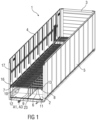
- Figure 1 shows a perspective view of a part of a vehicle body 1 for a commercial vehicle or a trailer or semi-trailer for a commercial vehicle.
- the vehicle body 1 comprises a loading floor 2, a side wall 3 running perpendicular to the latter and arranged on a front end face, two opposite side walls 4, 5 and, in a manner not shown in detail, a roof and a door opposite the side wall 3 and arranged on a rear end face.
- Figure 2 is a perspective view of a part of the vehicle body 1 according to Figure 1 shown, whereby the side wall 5 is not shown.
- loading level devices 6 are arranged over the entire length of the vehicle body 1, which are of identical design. To maintain clarity, the Figures 1 and 2 only one of the loading level devices 6 and its components are provided with reference symbols.
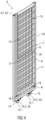
- FIG 3 and Figure 4 perspective views of such a loading level device 6 are shown in a use position and a stowed position.
- the loading level devices 6 each comprise two flat loading level elements 7, 8 which are coupled to one another via a level pivot axis A1 and can pivot about this axis, as well as a support element 9.
- a first loading level device 6 is arranged in an intermediate position and a third loading level device 6 is arranged in the stowage position.
- the remaining loading level devices 6 are arranged in the use position.
- the loading level elements 7, 8 each comprise a frame 10, 11 that runs all the way around and forms the front sides of the loading level elements 7, 8.
- a flat structure 12, 13 that covers the free space between the inner sides of the respective frame 10, 11, which in this case is formed by several longitudinal and transverse struts.
- the flat structures 12, 13 can also be arranged on a respective upper side of the frames 10, 11.
- the upper side of the frames 10, 11 is understood to be the side that faces away from the loading floor 2 in the use position.
- the flat structures 12, 13 can also be designed as a grid, perforated sheet or plate, for example. In embodiments not shown in more detail, the structures 12, 13 can also be omitted.
- a first loading level element 7 of the two loading level elements 7, 8 has two pivot fastening devices 14, 15 at an end facing away from the level pivot axis A, each of which comprises a fastening element 14.1, 15.1, by means of which the loading level element 7 can be fastened, in particular suspended, to the side wall 3, and a pivot device 14.2, 15.2 for realizing a side pivot axis A2 running parallel to the level pivot axis A1 and to the loading floor 2.
- the first loading level element 7 is thus fastened or can be fastened to the side wall 4 of the vehicle body 1 so as to be pivotable about the side pivot axis A2 running parallel to the level pivot axis A1.
- At least one side wall fastening structure 16, 17 corresponding to the fastening elements 14.1, 15.1 is provided on the side wall 4.
- two side wall fastening structures 16, 17 arranged at different heights on the side wall 4 are provided in order to fasten the loading level elements 7, 8 at different heights in the vehicle body 1 or to be able to arrange several loading level elements 7, 8 one above the other.
- more than two such fastening structures 16, 17 can also be arranged one above the other in order to realize finer gradations for arranging the loading level elements 7, 8 at different heights.
- the fastening elements 14.1, 15.1 and the corresponding side wall fastening structures 16, 17 are designed such that the fastening of the first loading level element 7 to the side wall 4 can be released again in a simple manner and the loading level element 7 can be fastened again at a different position on the side wall 4.
- the support element 9 in one possible embodiment has a length that can be variably adjusted perpendicular to the support pivot axis A3 and is in different lengths.
- the support element 9 is designed to be telescopic at least in sections.
- a second loading level element 8 of the loading level elements 7, 8 has two fastening devices 18, 19 at an end facing away from the plane pivot axis A1, by means of which it can be fastened and/or supported in the use position on the second side wall 5 of the vehicle body 1 opposite the first side wall 4.
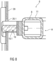
- at least one fastening device 18, 19 corresponding to the fastening devices 19 and in the Figures 7 and 8 shown in more detail side wall fastening structure 20 is provided.
- several side wall fastening structures 20 arranged at different heights on the side wall 5 can also be provided in order to fasten the loading level elements 7, 8 at different heights in the vehicle body 1 or to be able to arrange several loading level elements 7, 8 one above the other.
- the fastening devices 18, 19 and the corresponding side wall fastening structure 20 are designed such that the fastening of the second loading level element 8 to the side wall 5 can be released again in a simple manner and the loading level element 8 can be fastened again at a different position on the side wall 5.
- the support element 9 is arranged on at least one of the loading level elements 7, 8 and can be pivoted about a support pivot axis A3 running in the same direction as the level pivot axis A1.
- the level pivot axis A1 and the support pivot axis A3 coincide in a common axis.
- the two loading level elements 7, 8 are arranged such that the second loading level element 8 is attached to the side wall 5 of the vehicle body 1 and upper sides of both Loading level elements 7, 8 run in one plane.
- the support element 9 for supporting the loading level elements 7, 8 on the loading floor 2 is directed downwards starting from the undersides of the loading level elements 7, 8.
- the support element 9 has two support fastening devices 21, 22 for a force-fitting and/or form-fitting fastening to the loading floor 2.
- At least one floor fastening device 23 can be arranged on the loading floor 2 or at least one floor fastening device 23 can be integrated into the loading floor 2.
- the floor fastening device 23 is designed for a force-fitting and/or form-fitting coupling with the support fastening devices 21, 22 of the support element 9.
- the floor fastening device 23 is designed as a fastening rail embedded in the loading floor 2 or built on it.
- the floor fastening device 23 can also comprise several sleeves embedded in the loading floor 2 or built on it, for example screw sleeves, for force-fitting and/or form-fitting coupling with the support fastening devices 21, 22 of the support element 9.
- the loading level elements 7, 8 can also run in different levels in the use position, which have a height offset from one another and in particular run plane-parallel to one another.
- Such an embodiment can be achieved, for example, by means of several level pivot axes A1 and a spacer element located between them.
- the first loading level element 7 is directed upwards from the board pivot axis A2 with an upper side on the board wall 4 and the second loading level element 8 is directed downwards from the level pivot axis A1 with an underside on an underside of the first loading level element 7.
- the support element 9 is directed downwards from the support pivot axis A3 in the stowed position on the underside of the first loading level element 7 and is positioned between the two loading level elements 7, 8. If the loading level elements 7, 8 do not have any flat structures 12, 13, the second loading level element 8 can completely "immerse" in the first loading level element 7 or penetrate it in the stowed position and thus also rest against the side wall 4 with its underside.
- the support element 9 is guided by gravity in one possible embodiment.
- the support element 9 is coupled to at least one of the loading level elements 7, 8 by means of a guide structure 24 in such a way that the support element 9 is forcibly moved from a stowed position to a supported position when transferred from the stowed position to the use position and from the supported position to the stowed position when transferred from the use position to the stowed position.
- the first loading level element 7 has a cavity H on its underside for at least partially receiving the loading level element 8 pivoted to the first loading level element 7 in the stowed position and the support element 9.
- This cavity H can alternatively also be formed in the second loading level element 8 for receiving the first loading level element 7 and the support element 9.
- a width of the frame 11 of the loading level element 8 running in the direction of the plane pivot axis A1 is smaller than a width of the frame 10 of the first loading level element 7 running in the direction of the plane pivot axis A1.
- a length of the frame 11 is also smaller than a length of the frame 10.
- a width of the support element 9 running in the direction of the support pivot axis A3 is smaller than a clear width of the smaller frame 11, so that the support element 9 can be folded into a clear width of the smaller frame 11.
- this cavity H it can be achieved, for example, that in the stowed position, when flat structures 12, 13 are arranged on the upper sides of the frames 10, 11, the upper side of the frame 11 of the second loading level element 8 runs in a plane with the underside of the frame 10 of the first loading level element 7 and the loading level device 6 thus has a particularly small thickness in the folded-in stowed position.
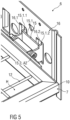
- FIGs 5 and 6 is a section of the loading level device 2 according to Figure 3 in the area of the swivel fastening device 15 and the side wall fastening structure 16.
- the fastening element 15.1 of the swivel fastening device 15 has two hook elements 15.1.1, 15.1.2, which can be hooked into corresponding openings 16.1, 16.2 of the side wall fastening structure 16.
- the fastening element 14.1 is designed analogously to the fastening element 15.1.
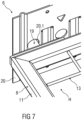
- FIGs 7 and 8 is a section of the loading level device 2 according to Figure 3 in the area of the fastening device 19 and the side wall fastening structure 20.
- the fastening device 19 is designed as a bolt, which has a material recess 19.1 on its underside.
- the side wall fastening structure 20 has an opening 20.1 corresponding to the fastening device 19, into which the fastening device 19 can be inserted and can be hooked into the material recess 19.
- the fastening structure 18 is designed analogously to the fastening structure 19.
- the fastening device 19 can also be designed in a different form. Spring-loaded or otherwise movable parts can also be provided on the fastening device 19 for fixing it to or in the side wall fastening structure 20.
- the side wall fastening structures 16, 17, 20 in the illustrated embodiments are designed as identical parts, in particular in the form of a flat rail, with the openings 16.1, 16.2, 20.1.
Landscapes
- Engineering & Computer Science (AREA)
- Chemical & Material Sciences (AREA)
- Combustion & Propulsion (AREA)
- Transportation (AREA)
- Mechanical Engineering (AREA)
- Fittings On The Vehicle Exterior For Carrying Loads, And Devices For Holding Or Mounting Articles (AREA)
Priority Applications (1)
| Application Number | Priority Date | Filing Date | Title |
|---|---|---|---|
| EP23179765.5A EP4477504A1 (fr) | 2023-06-16 | 2023-06-16 | Dispositif de plan de charge, carrosserie de véhicule et véhicule |
Applications Claiming Priority (1)
| Application Number | Priority Date | Filing Date | Title |
|---|---|---|---|
| EP23179765.5A EP4477504A1 (fr) | 2023-06-16 | 2023-06-16 | Dispositif de plan de charge, carrosserie de véhicule et véhicule |
Publications (1)
| Publication Number | Publication Date |
|---|---|
| EP4477504A1 true EP4477504A1 (fr) | 2024-12-18 |
Family
ID=86862111
Family Applications (1)
| Application Number | Title | Priority Date | Filing Date |
|---|---|---|---|
| EP23179765.5A Withdrawn EP4477504A1 (fr) | 2023-06-16 | 2023-06-16 | Dispositif de plan de charge, carrosserie de véhicule et véhicule |
Country Status (1)
| Country | Link |
|---|---|
| EP (1) | EP4477504A1 (fr) |
Citations (4)
| Publication number | Priority date | Publication date | Assignee | Title |
|---|---|---|---|---|
| EP0005960B1 (fr) * | 1978-05-25 | 1981-09-02 | Bkl Extrusions Limited | Planchers porteurs de charge |
| US4995322A (en) * | 1986-12-04 | 1991-02-26 | Frederick Percy R | Externally mounted R.V. table |
| EP0818348A2 (fr) * | 1996-07-12 | 1998-01-14 | Spier GmbH & Co. Fahrzeugwerk KG | Plancher intermédiaire pour caisses de camions |
| US20060255609A1 (en) * | 2005-05-11 | 2006-11-16 | Squyres Jerrell P | Double jointed hinge and foldable deck using same |
-
2023
- 2023-06-16 EP EP23179765.5A patent/EP4477504A1/fr not_active Withdrawn
Patent Citations (4)
| Publication number | Priority date | Publication date | Assignee | Title |
|---|---|---|---|---|
| EP0005960B1 (fr) * | 1978-05-25 | 1981-09-02 | Bkl Extrusions Limited | Planchers porteurs de charge |
| US4995322A (en) * | 1986-12-04 | 1991-02-26 | Frederick Percy R | Externally mounted R.V. table |
| EP0818348A2 (fr) * | 1996-07-12 | 1998-01-14 | Spier GmbH & Co. Fahrzeugwerk KG | Plancher intermédiaire pour caisses de camions |
| US20060255609A1 (en) * | 2005-05-11 | 2006-11-16 | Squyres Jerrell P | Double jointed hinge and foldable deck using same |
Similar Documents
| Publication | Publication Date | Title |
|---|---|---|
| DE69422497T2 (de) | Verstellbare palette für transport | |
| DE69315670T2 (de) | Einstellbarer Querholm für einen Fahrzeug-Gepäckträger | |
| DE68909281T2 (de) | Verstellbare Säule für ein Lastkraftfahrzeug mit verschiebbarer Abdeckung. | |
| EP3495288A1 (fr) | Conteneur pour le transport d'un véhicule | |
| EP3699058A1 (fr) | Agencement d'un véhicule ferroviaire et dispositif support | |
| EP1522455B1 (fr) | Dispositif de protection de chargement dans les unités de transport | |
| DE102011115552A1 (de) | Klappregal | |
| EP3699057A1 (fr) | Dispositif porteur élevable | |
| DE29801555U1 (de) | Aufbau für ein Transportfahrzeug | |
| EP4477504A1 (fr) | Dispositif de plan de charge, carrosserie de véhicule et véhicule | |
| EP1003682A1 (fr) | Element de retenue et procede permettant de retenir des conteneurs | |
| EP3909807A1 (fr) | Véhicule | |
| DE102015006053B4 (de) | Ladungssicherungsrungensystem für Nutzfahrzeuge | |
| EP0241827A2 (fr) | Dispositif pour emmener un chariot à fourche sur un camion | |
| DE102012006387B4 (de) | Verdeckgestell für einen Planenaufbau sowie Schiebestrebe | |
| DE60030509T2 (de) | Anordnung im Frachtraum | |
| DE69018055T2 (de) | Verbesserung an Rückhalteeinrichtung für Fahrzeuge und Container. | |
| DE3723452A1 (de) | Schiebeverdeckgestell fuer lastfahrzeuge | |
| DE102008037092B4 (de) | Kippbrücke für ein Kipperfahrzeug | |
| EP4707136A1 (fr) | Carrosserie de véhicule et véhicule | |
| DE102024126924A1 (de) | Faltbarer Anhänger | |
| DE10104939B4 (de) | Fahrzeugsitz mit einem auf einem Sitzuntergestell schwenkbar gelagerten Sitzrahmen | |
| DE1956392A1 (de) | Schiebeverdeck,insbesondere fuer Lastkraftwagen und Anhaenger | |
| DE10307598A1 (de) | Vorrichtung zur Sicherung von rollenförmigen Ladegütern, insbesondere liegenden Papierrollen auf dem Ladeboden von Fahrzeugen, insbesondere Eisenbahngüterwagen | |
| DE10104941B4 (de) | Fahrzeugsitz mit einem auf einem Sitzuntergestell schwenkbar gelagerten Sitzrahmen |
Legal Events
| Date | Code | Title | Description |
|---|---|---|---|
| PUAI | Public reference made under article 153(3) epc to a published international application that has entered the european phase |
Free format text: ORIGINAL CODE: 0009012 |
|
| STAA | Information on the status of an ep patent application or granted ep patent |
Free format text: STATUS: THE APPLICATION HAS BEEN PUBLISHED |
|
| AK | Designated contracting states |
Kind code of ref document: A1 Designated state(s): AL AT BE BG CH CY CZ DE DK EE ES FI FR GB GR HR HU IE IS IT LI LT LU LV MC ME MK MT NL NO PL PT RO RS SE SI SK SM TR |
|
| STAA | Information on the status of an ep patent application or granted ep patent |
Free format text: STATUS: THE APPLICATION IS DEEMED TO BE WITHDRAWN |
|
| 18D | Application deemed to be withdrawn |
Effective date: 20250619 |