EP4477603A1 - Alignement basé sur la lumière pour l'installation d'un dispositif de détection de personne - Google Patents
Alignement basé sur la lumière pour l'installation d'un dispositif de détection de personne Download PDFInfo
- Publication number
- EP4477603A1 EP4477603A1 EP24181238.7A EP24181238A EP4477603A1 EP 4477603 A1 EP4477603 A1 EP 4477603A1 EP 24181238 A EP24181238 A EP 24181238A EP 4477603 A1 EP4477603 A1 EP 4477603A1
- Authority
- EP
- European Patent Office
- Prior art keywords
- sensor assembly
- assembly
- elevator
- sensor
- light pattern
- Prior art date
- Legal status (The legal status is an assumption and is not a legal conclusion. Google has not performed a legal analysis and makes no representation as to the accuracy of the status listed.)
- Pending
Links
Images



Classifications
-
- B—PERFORMING OPERATIONS; TRANSPORTING
- B66—HOISTING; LIFTING; HAULING
- B66B—ELEVATORS; ESCALATORS OR MOVING WALKWAYS
- B66B5/00—Applications of checking, fault-correcting, or safety devices in elevators
- B66B5/0043—Devices enhancing safety during maintenance
- B66B5/005—Safety of maintenance personnel
-
- B—PERFORMING OPERATIONS; TRANSPORTING
- B66—HOISTING; LIFTING; HAULING
- B66B—ELEVATORS; ESCALATORS OR MOVING WALKWAYS
- B66B1/00—Control systems of elevators in general
- B66B1/02—Control systems without regulation, i.e. without retroactive action
- B66B1/06—Control systems without regulation, i.e. without retroactive action electric
-
- B—PERFORMING OPERATIONS; TRANSPORTING
- B66—HOISTING; LIFTING; HAULING
- B66B—ELEVATORS; ESCALATORS OR MOVING WALKWAYS
- B66B1/00—Control systems of elevators in general
- B66B1/34—Details, e.g. call counting devices, data transmission from car to control system, devices giving information to the control system
- B66B1/3492—Position or motion detectors or driving means for the detector
-
- B—PERFORMING OPERATIONS; TRANSPORTING
- B66—HOISTING; LIFTING; HAULING
- B66B—ELEVATORS; ESCALATORS OR MOVING WALKWAYS
- B66B3/00—Applications of devices for indicating or signalling operating conditions of elevators
- B66B3/002—Indicators
-
- B—PERFORMING OPERATIONS; TRANSPORTING
- B66—HOISTING; LIFTING; HAULING
- B66B—ELEVATORS; ESCALATORS OR MOVING WALKWAYS
- B66B5/00—Applications of checking, fault-correcting, or safety devices in elevators
- B66B5/0006—Monitoring devices or performance analysers
- B66B5/0018—Devices monitoring the operating condition of the elevator system
- B66B5/0031—Devices monitoring the operating condition of the elevator system for safety reasons
-
- G—PHYSICS
- G08—SIGNALLING
- G08B—SIGNALLING SYSTEMS, e.g. PERSONAL CALLING SYSTEMS; ORDER TELEGRAPHS; ALARM SYSTEMS
- G08B5/00—Visible signalling systems, e.g. visible personal calling systems or remote indication of seats occupied
- G08B5/22—Visible signalling systems, e.g. visible personal calling systems or remote indication of seats occupied using electric transmission; using electromagnetic transmission
- G08B5/36—Visible signalling systems, e.g. visible personal calling systems or remote indication of seats occupied using electric transmission; using electromagnetic transmission using visible light sources
Definitions
- the embodiments described herein relate to elevator systems, and more particularly, to an elevator system including one or more sensor assemblies to detect a person in a pit of the elevator system.
- an assembly associated with detection of a human within an elevator hoistway includes a sensor assembly and a position indicator affixed to the sensor assembly and operable to emit a visual light pattern.
- the position indicator is movable with the sensor assembly to indicate to a user when the sensor assembly is in a desired mounting position.
- Particular embodiments further may include at least one, or a plurality of, the following optional features, alone or in combination with each other:
- a position of the visual light pattern indicates to a user when the sensor assembly is in the desired mounting position.
- the visible light pattern emitted by the position indicator is aligned with a target when the sensor assembly is in the desired mounting position.
- the visual light pattern includes a plurality of dots and/or lines.
- the visual light pattern includes a single point.
- the visual light pattern includes alphanumeric characters.
- the visual light pattern is configured to change color when the sensor assembly is arranged at or near the desired mounting position.
- the visual light pattern includes alphanumeric characters when the sensor assembly is arranged at or near the desired mounting position.
- the position indicator is removably affixed to the sensor assembly.
- the senor assembly includes a connecting member and the position indicator being directly coupled to the connecting member.
- the assembly includes a mounting bracket and a locking mechanism.
- the sensor assembly is movably coupled to the mounting bracket and the locking mechanism is operable to lock a position of the sensor assembly relative to the mounting bracket.
- further embodiments include at least one device for detecting a relative position of the mounting bracket to at least one of a horizontal or vertical plane.
- the sensor assembly includes a sensor.
- the sensor includes at least one of a LIDAR sensor, a millimeter wave RADAR sensor and an RGBD camera.
- an elevator system includes the assembly.
- the elevator system includes a hoistway, an elevator car and a counterweight configured to travel in the hoistway, an elevator pit located at a bottom of the hoistway and a ladder extending from the elevator pit.
- the sensor assembly is mounted at one or more of the elevator car, the counterweight, adjacent to the ladder, within the elevator pit, or to a wall of the hoistway.
- a method of installing a sensor assembly within an area to be monitored of an elevator system includes attaching a sensor assembly to a mounting surface of the elevator system and aligning a visual light pattern generated by a position indicator coupled to the sensor assembly with to a target to locate the sensor assembly at the desired mounting position relative to the mounting surface.
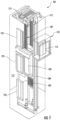
- FIG. 1 is a perspective view of an elevator system 101 including an elevator car 103, a counterweight 105, a tension member 107, a guide rail 109, a machine 111, a position reference system 113, and a controller 115.
- the elevator car 103 and counterweight 105 are connected to each other by the tension member 107.
- the tension member 107 may include or be configured as, for example, ropes, steel cables, and/or coated-steel belts.
- the counterweight 105 is configured to balance a load of the elevator car 103 and is configured to facilitate movement of the elevator car 103 concurrently and in an opposite direction with respect to the counterweight 105 within an elevator shaft or hoistway 117 and along the guide rail 109.
- the tension member 107 engages the machine 111, which is part of an overhead structure of the elevator system 101.
- the machine 111 is configured to control movement between the elevator car 103 and the counterweight 105.
- the position reference system 113 may be mounted on a fixed part at the top of the hoistway 117, such as on a support or guide rail, and may be configured to provide position signals related to a position of the elevator car 103 within the hoistway 117. In other embodiments, the position reference system 113 may be directly mounted to a moving component of the machine 111, or may be located in other positions and/or configurations as known in the art.
- the position reference system 113 can be any device or mechanism for monitoring a position of an elevator car and/or counterweight, as known in the art.
- the position reference system 113 can be an encoder, sensor, or other system and can include velocity sensing, absolute position sensing, etc., as will be appreciated by those of skill in the art.
- the controller 115 may be located, as shown, in a controller room 121 of the elevator shaft 117 and is configured to control the operation of the elevator system 101, and particularly the elevator car 103. It is to be appreciated that the controller 115 need not be in the controller room 121 but may be in the hoistway or other location in the elevator system. For example, the controller 115 may provide drive signals to the machine 111 to control the acceleration, deceleration, leveling, stopping, etc. of the elevator car 103. The controller 115 may also be configured to receive position signals from the position reference system 113 or any other desired position reference device. When moving up or down within the hoistway 117 along guide rail 109, the elevator car 103 may stop at one or more landings 125 as controlled by the controller 115.
- controller 115 can be located and/or configured in other locations or positions within the elevator system 101.
- the controller 115 may be located remotely or in a distributed computing network (e.g., cloud computing architecture).
- the controller 115 may be implemented using a processor-based machine, such as a personal computer, server, distributed computing network, etc.
- the machine 111 may include a motor or similar driving mechanism.
- the machine 111 is configured to include an electrically driven motor.
- the power supply for the motor may be any power source, including a power grid, which, in combination with other components, is supplied to the motor.
- the machine 111 may include a traction sheave that imparts force to tension member 107 to move the elevator car 103 within hoistway 117.
- the elevator system 101 also includes one or more elevator doors 104.
- the elevator door 104 may be attached to the elevator car 103 or the elevator door 104 may be located on a landing 125 of the elevator system 101, or both. Embodiments disclosed herein may be applicable to both an elevator door 104 attached to the elevator car 103 or an elevator door 104 located on a landing 125 of the elevator system 101, or both.
- the elevator door 104 opens to allow passengers to enter and exit the elevator car 103.
- FIG. 1 is merely a non-limiting example presented for illustrative and explanatory purposes.
- the elevator system 101 includes a safety chain.
- a safety chain is a known component of elevator systems and typically includes a number of contacts (e.g., relays) in series that control power to the elevator system machine 111 to enable or disable movement of the elevator car 103. If any of the contacts of the safety chain are open, the elevator car 103 is prevented from moving. Accordingly, when a mechanic wants to access the hoistway 117, it is desirable to open the safety chain to prevent movement of the elevator car 103.
- At least one sensor assembly 200 operable to detect the presence of a human may be mounted within the hoistway 117.
- the one or more sensor assemblies 200 may be configured to move with the elevator car 103 or the counterweight 105.
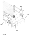
- at least one sensor assembly 200 is mounted to a handrail 130 located at the top 106 of the elevator car 103.
- a sensor assembly 200 mounted at any suitable location of the elevator car 103, including the bottom thereof, and the counterweight 105 are contemplated herein.
- the elevator system 101 may include a sensor assembly 200 mounted at a fixed location within the hoistway 117.
- the sensor assembly 200 may be mounted to a wall of the hoistway itself, such as near a landing door or pit door for example, and/or may be arranged at or adjacent to an area of the hoistway 117 commonly occupied or accessed by maintenance personnel.
- one or more sensor assemblies 200 may be positioned to monitor the elevator pit for maintenance persons.
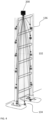
- a sensor assembly 200 may be mounted within the elevator pit, generally illustrated at 132, such as at a location at or slightly offset from the floor 134 thereof for example.
- the sensor assembly 200 is illustrated as being located at a corner of the elevator pit 132, embodiments where the sensor assembly 200 is located adjacent to only a single wall of the hoistway 117 are also within the scope of the disclosure.
- the sensor assembly may be configured to monitor within a plane oriented substantially parallel to the wall, and/or a plane arranged at a non-parallel angle to the wall.
- a sensor assembly 200 may be positioned adjacent to the ladder 136 configured to provide access to the elevator pit 132. In the non-limiting embodiment of FIG. 4 the sensor assembly 200 is arranged within the vertical plane of the ladder 136. It should be appreciated that the suitable locations of a sensor assembly 200 illustrated and described herein are intended as an example only and that a sensor assembly may be arranged at any location within or associated with the hoistway 117. Further, although the sensor assembly 200 is illustrated and described herein as monitoring within a two-dimensional plane, in some embodiments, the sensor assembly may be capable of monitoring in three-dimensions.
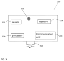
- the sensor assembly 200 includes at least one sensor.
- the sensor 202 may be a distance sensor that generates distance measurements in a two-dimensional or three-dimensional field of view.
- the sensor 202 may be implemented using a LIDAR sensor, a millimeter wave RADAR sensor, an RGBD camera or other distance measuring sensors.
- the sensor assembly 200 includes a processor 204 that controls operation of the sensor assembly 200.
- the processor 204 may be implemented using a general-purpose microprocessor executing a computer program stored on a storage medium to perform the operations described herein.
- the processor 204 may be implemented in hardware (e.g., ASIC, FPGA) or in a combination of hardware/software.
- the processor 204 allows the sensor assembly 200 to perform computations locally, also referred to as edge computing.
- the processor 204 can send commands to other components of the elevator system 101, such as the elevator controller 115 for example, based on a result of the local computations.
- the sensor assembly 200 includes one or more indicators 205, such as a visual indicator and/or an audio indicator for example, operable to indicate an operation status of the sensor assembly 200.
- the indicator 205 may identify one or more of when the sensor assembly 200 is active, when the sensor assembly 200 has detected the presence of a person within the area being monitored by the sensor 202, whether or not the sensor assembly 200 is functioning properly, and when the sensor assembly is properly positioned at a desired mounting location, as will be described in more detail below.
- the sensor assembly 200 includes another type of indicator 205, and/or where the indicator is operable to identify other operating conditions are also within the scope of the disclosure.
- the sensor assembly 200 includes a memory 206 that may store a computer program executable by processor 204, reference data, sensor data, etc.
- the memory 206 may be implemented using known devices such a random-access memory.
- the sensor assembly 200 includes a communication unit 208 which allows the sensor assembly 200 to communicate with other components of the elevator system 101, such as other sensor assemblies and/or the elevator controller 115.
- the communication unit 208 may be implemented using wired connections (e.g., LAN, ethernet, twisted pair, etc.) or wireless connections (e.g., WiFi, NFC, BlueTooth, etc.).
- the sensor assembly 200 can open a safety chain of the elevator system 101 under certain conditions.
- the sensor assembly 200 can control a safety chain contact 210 in order to open or close the safety chain.
- the safety chain contact 210 is one of several contacts that make up the safety chain.
- the sensor assembly 200 may include a mounting assembly 220 for mounting the sensor assembly 200 at a desired location within the hoistway 117.
- the sensor assembly 200 includes a connecting member 222 and a mounting bracket or clamp 224 of the mounting assembly 220 is operably coupled to the connecting member 222.
- the mounting bracket 224 is an L-shaped or corner bracket having a first leg 226 and a second leg 228. As shown, a portion of the first leg, such as a first end 230 thereof for example, is fixedly mounted to a portion of the second leg 228, such as an adjacent end 232 of the second leg 228.
- the mounting bracket 224 is affixable to a mounting surface within the hoistway 117, such as to one or more walls of the hoistway 117 for example, via one or more fasteners or another suitable connector.
- the mounting bracket 224 may include at least one device for detecting a relative position of the mounting bracket 224, such as to a horizontal or vertical plane.
- the mounting bracket 224 includes a first bubble level 240 associated with the first leg 226 thereof and a second bubble level 240 associated with the second leg 228 thereof.
- the device for detecting the position of the mounting bracket 224 includes a digital or laser level, or a micro-electromechanical system (MEMS) device.
- detection of the relative position of the mounting bracket 224 may be performed by a tool separate from the mounting bracket 224, such as by a level removably mountable on a surface of the mounting bracket for example.
- MEMS micro-electromechanical system
- the connecting member 222 affixed to the sensor assembly 200 is movably coupled to a portion of the mounting bracket 224.
- a hinge is arranged at the interface between the connecting member 222 and the mounting bracket 224 such that the connecting member 222, and therefore the sensor assembly 200 coupled to the connecting member 222, is rotatable about an axis X relative to the mounting bracket 224.
- the connecting member 222 and sensor assembly is configured to slide relative to the mounting bracket 224.
- the interface between the connecting member 222 and the mounting bracket 224 such as the hinge for example, includes tooling 242, such as a plurality of markings for example, identifying various angles of the sensor assembly 200 relative to the mounting bracket 224 or a corresponding surface to which the mounting bracket 224 is affixed.
- tooling 242 such as a plurality of markings for example, identifying various angles of the sensor assembly 200 relative to the mounting bracket 224 or a corresponding surface to which the mounting bracket 224 is affixed.
- a position indicator 250 may be connectable to the sensor assembly 200 and movable therewith relative to the mounting assembly 220.
- the position indicator 250 is affixed to an end 252 of the connecting member 222, opposite the mounting bracket 224.
- the position indicator 250 is an installation tool removably coupled to the sensor assembly 200 during installation of the sensor assembly 200 about the elevator system 101.
- the position indicator 250 is typically removed or disconnected therefrom.
- the position indicator 250 may be intended to remain affixed to the sensor assembly 200 even after the installation within an elevator system 101.
- the position indicator 250 is a visual indicator having one or more light sources 254 operable to emit a light therefrom into the hoistway 117.
- the position indicator 250 may be designed such that when attached to the sensor assembly 200, light is emitted from the position indicator 250 in a direction parallel to the signals emitted from the sensor 202.
- embodiments where the position indicator 250 is configured to emit light in another direction are also within the scope of the disclosure.
- the at least one light source of the position indicator 250 is operable to emit a light pattern that is visible on one or more surfaces surrounding the area to be monitored by the sensor assembly 200.
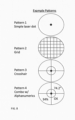
- the visible light pattern generated by the position indicator 250 may have any suitable configuration. Examples of such configurations are illustrated in FIG. 8 . These patterns include but are not limited to a single point similar to a laser, or to a series of lines and/or dots, such as a grid or a crosshair for example.
- the visible light pattern output from the position indicator 250 may additionally or alternatively include alphanumeric characters.
- the visible light pattern itself may be able to indicate to a user the actual position of the sensor assembly 200 relative to the mounting bracket or may provide feedback to a user, such as by identifying when the sensor assembly 200 is arranged at or near the desired mounting position.
- the visible light pattern includes alphanumeric characters when the sensor assembly 200 is arranged at or near the desired mounting position.
- the color of the visible light pattern may change when the sensor assembly 200 is arranged at or near the desired mounting position.
- the color of the light may change based on the position of the sensor assembly relative to the desired mounting position.
- the light may be green when the sensor assembly is at the desired mounting position, the light may be yellow when the sensor assembly is within a first threshold of the desired mounting position, and the light may be red when the sensor assembly is outside of the first threshold of the desired mounting position.
- the light may simply be a first color when the sensor assembly is at an acceptable position, i.e., either at or within a first threshold of the desired mounting position and may be a second color when the sensor assembly is not at an acceptable mounting position.
- the light pattern may include a plurality of lines and/or dots, a single line, a point, or any other configuration.
- the visible light pattern generated by the position indicator 250 is dependent upon the location of the area to be monitored by the sensor assembly being installed. For example, a first visible light pattern may be generated when mounting a sensor assembly 200 at or near the top 106 of the elevator car 103 and a second, visible light pattern may be generated when mounting a sensor assembly 200 in the elevator pit 132.
- the sensor assembly 200 such as the memory 206 for example, may be pre-programmed with setup or position information associated with the desired or desired mounting position of the sensor assembly 200 within the hoistway 117.
- the position indicator 250 itself may be pre-programmed with setup information.
- the setup or position information may be based on the expected viewing layout of the hoistway 117 and/or the specific installation location of the sensor assembly 200 within the hoistway 117. In an embodiment, this setup information is not stored within the sensor assembly 200. Rather, the setup information may be communicated to the sensor assembly 200 from another source, such as the elevator controller 115 for example.
- a person will mount the mounting bracket 224 to one or more surfaces of the elevator system 101.
- the installer will use at least one leveling device, such as devices 240 for example, to ensure that one or more surfaces of the mounting bracket 224 are arranged within a desired plane.
- the installer may be provided with one or more desired objects or features of the elevator system 101 to use as a target for determining when the sensor assembly 200 is in the proper position. As the installer moves the sensor assembly 200 relative to the mounting bracket 224, the visual light pattern generated by the position indicator 250 will also move.
- the installer will continue to move the sensor assembly 200 until the visual light pattern is aligned with the target, thereby indicating that the sensor assembly 200 is at the desired mounting position.
- the position of sensor assembly 200 may be locked relative to the mounting bracket 224.
- Any suitable locking mechanism illustrated schematically at 244 in FIG. 6 , may be used to retain the sensor assembly 200 in the desired mounting position. Examples of such locking mechanisms, include but are not limited to a detent or a tightening screw.
- the position indicator 250 when coupled to the sensor assembly 200, may be used to learn one or more boundaries of the area being monitored. For example, the sensor assembly 200 may be moved relative to the mounting bracket between a first position defined by alignment of the position indicator 250 with a first target and a second position defined by alignment of the position indicator 250 with a second distinct target. In some embodiments the data collected by the sensor 202 as the sensor assembly 200 moves between the first and second positions may be used to calculate or determine the proper mounting position of the sensor assembly 200 relative to the mounting bracket 224.
Landscapes
- Engineering & Computer Science (AREA)
- Automation & Control Theory (AREA)
- Physics & Mathematics (AREA)
- Electromagnetism (AREA)
- General Physics & Mathematics (AREA)
- Computer Networks & Wireless Communication (AREA)
- Indicating And Signalling Devices For Elevators (AREA)
Applications Claiming Priority (1)
| Application Number | Priority Date | Filing Date | Title |
|---|---|---|---|
| US18/332,982 US20240409366A1 (en) | 2023-06-12 | 2023-06-12 | Light based alignment for installation of person detection device |
Publications (1)
| Publication Number | Publication Date |
|---|---|
| EP4477603A1 true EP4477603A1 (fr) | 2024-12-18 |
Family
ID=91481670
Family Applications (1)
| Application Number | Title | Priority Date | Filing Date |
|---|---|---|---|
| EP24181238.7A Pending EP4477603A1 (fr) | 2023-06-12 | 2024-06-10 | Alignement basé sur la lumière pour l'installation d'un dispositif de détection de personne |
Country Status (3)
| Country | Link |
|---|---|
| US (1) | US20240409366A1 (fr) |
| EP (1) | EP4477603A1 (fr) |
| CN (1) | CN119117826A (fr) |
Citations (3)
| Publication number | Priority date | Publication date | Assignee | Title |
|---|---|---|---|---|
| JP2015020838A (ja) * | 2013-07-17 | 2015-02-02 | 株式会社日立ビルシステム | エレベータの警報装置 |
| US20170302909A1 (en) * | 2016-04-18 | 2017-10-19 | Otis Elevator Company | Auto commissioning system and method |
| US20220003869A1 (en) * | 2020-07-02 | 2022-01-06 | Sick Ag | Sensor device and alignment method |
-
2023
- 2023-06-12 US US18/332,982 patent/US20240409366A1/en active Pending
- 2023-11-22 CN CN202311563184.8A patent/CN119117826A/zh active Pending
-
2024
- 2024-06-10 EP EP24181238.7A patent/EP4477603A1/fr active Pending
Patent Citations (3)
| Publication number | Priority date | Publication date | Assignee | Title |
|---|---|---|---|---|
| JP2015020838A (ja) * | 2013-07-17 | 2015-02-02 | 株式会社日立ビルシステム | エレベータの警報装置 |
| US20170302909A1 (en) * | 2016-04-18 | 2017-10-19 | Otis Elevator Company | Auto commissioning system and method |
| US20220003869A1 (en) * | 2020-07-02 | 2022-01-06 | Sick Ag | Sensor device and alignment method |
Also Published As
| Publication number | Publication date |
|---|---|
| US20240409366A1 (en) | 2024-12-12 |
| CN119117826A (zh) | 2024-12-13 |
Similar Documents
| Publication | Publication Date | Title |
|---|---|---|
| EP3882204B1 (fr) | Système d'inspection d'ascenseur doté d'une plateforme robotique configurée pour développer des données de modèle de cage à partir de données de capteur | |
| EP3401264B1 (fr) | Systèmes et procédés d'inspection de contrepoids d'ascenseur automatiques | |
| CN113401764B (zh) | 具有构造成检查井道中构件的机器人平台的电梯检查系统 | |
| CN111634780A (zh) | 控制电梯轿厢的移动 | |
| EP3599204A1 (fr) | Système et méthode d'inspection d'un composant d'ascenseur | |
| EP3424858B1 (fr) | Systèmes de projection d'espace d'entretien d'un ascenseur | |
| EP3882203B1 (fr) | Système d'inspection d'ascenseur doté d'une plateforme robotique configurée pour développer des données de modèle de cage à partir de systèmes d'ascenseur connectés à un réseau | |
| EP3882202B1 (fr) | Système d'inspection d'ascenseur ayant une plate-forme robotique conçue avec un propulseur de plate-forme | |
| JP2008285265A (ja) | エレベータ強制減速装置 | |
| EP4477603A1 (fr) | Alignement basé sur la lumière pour l'installation d'un dispositif de détection de personne | |
| EP4477597A1 (fr) | Guide d'alignement d'ensemble capteur pour détection de personne | |
| EP3828115B1 (fr) | Système d'arrêt d'urgence pour ascenseur | |
| EP3882205B1 (fr) | Système d'inspection d'ascenseur comprenant un robot conçu pour inspecter les conditions de fonctionnement de la cabine d'ascenseur | |
| EP4477604A1 (fr) | Système d'ascenseur comprenant un ensemble capteur pour la détection de personnes | |
| EP4477606A1 (fr) | Surveillance du tendeur de câble de compensation dans une fosse d'ascenseur | |
| EP4477598A1 (fr) | Surveillance de fosse d'ascenseur et vérification d'intégrité d'un système de surveillance | |
| EP4206107B1 (fr) | Détection de défaut d'alignement de composants | |
| EP4477602A1 (fr) | Système d'ascenseur comprenant une interface de sécurité de fosse | |
| TWM670985U (zh) | 電梯系統 | |
| HK40000550B (en) | Automatic elevator inspection systems and methods | |
| HK40000550A (en) | Automatic elevator inspection systems and methods |
Legal Events
| Date | Code | Title | Description |
|---|---|---|---|
| PUAI | Public reference made under article 153(3) epc to a published international application that has entered the european phase |
Free format text: ORIGINAL CODE: 0009012 |
|
| STAA | Information on the status of an ep patent application or granted ep patent |
Free format text: STATUS: THE APPLICATION HAS BEEN PUBLISHED |
|
| AK | Designated contracting states |
Kind code of ref document: A1 Designated state(s): AL AT BE BG CH CY CZ DE DK EE ES FI FR GB GR HR HU IE IS IT LI LT LU LV MC ME MK MT NL NO PL PT RO RS SE SI SK SM TR |
|
| STAA | Information on the status of an ep patent application or granted ep patent |
Free format text: STATUS: REQUEST FOR EXAMINATION WAS MADE |
|
| 17P | Request for examination filed |
Effective date: 20250613 |
|
| GRAP | Despatch of communication of intention to grant a patent |
Free format text: ORIGINAL CODE: EPIDOSNIGR1 |
|
| STAA | Information on the status of an ep patent application or granted ep patent |
Free format text: STATUS: GRANT OF PATENT IS INTENDED |
|
| GRAS | Grant fee paid |
Free format text: ORIGINAL CODE: EPIDOSNIGR3 |
|
| INTG | Intention to grant announced |
Effective date: 20260312 |