EP4477809A1 - Robinetterie sanitaire et système de robinetterie sanitaire - Google Patents
Robinetterie sanitaire et système de robinetterie sanitaire Download PDFInfo
- Publication number
- EP4477809A1 EP4477809A1 EP24177303.5A EP24177303A EP4477809A1 EP 4477809 A1 EP4477809 A1 EP 4477809A1 EP 24177303 A EP24177303 A EP 24177303A EP 4477809 A1 EP4477809 A1 EP 4477809A1
- Authority
- EP
- European Patent Office
- Prior art keywords
- sanitary fitting
- water
- lever
- fitting according
- connection
- Prior art date
- Legal status (The legal status is an assumption and is not a legal conclusion. Google has not performed a legal analysis and makes no representation as to the accuracy of the status listed.)
- Pending
Links
Images



Classifications
-
- E—FIXED CONSTRUCTIONS
- E03—WATER SUPPLY; SEWERAGE
- E03C—DOMESTIC PLUMBING INSTALLATIONS FOR FRESH WATER OR WASTE WATER; SINKS
- E03C1/00—Domestic plumbing installations for fresh water or waste water; Sinks
- E03C1/02—Plumbing installations for fresh water
- E03C1/05—Arrangements of devices on wash-basins, baths, sinks, or the like for remote control of taps
- E03C1/055—Electrical control devices, e.g. with push buttons, control panels or the like
-
- E—FIXED CONSTRUCTIONS
- E03—WATER SUPPLY; SEWERAGE
- E03B—INSTALLATIONS OR METHODS FOR OBTAINING, COLLECTING, OR DISTRIBUTING WATER
- E03B7/00—Water main or service pipe systems
- E03B7/006—Arrangements or methods for cleaning or refurbishing water conduits
-
- E—FIXED CONSTRUCTIONS
- E03—WATER SUPPLY; SEWERAGE
- E03C—DOMESTIC PLUMBING INSTALLATIONS FOR FRESH WATER OR WASTE WATER; SINKS
- E03C1/00—Domestic plumbing installations for fresh water or waste water; Sinks
- E03C1/02—Plumbing installations for fresh water
- E03C1/04—Water-basin installations specially adapted to wash-basins or baths
- E03C1/0412—Constructional or functional features of the faucet handle
-
- F—MECHANICAL ENGINEERING; LIGHTING; HEATING; WEAPONS; BLASTING
- F16—ENGINEERING ELEMENTS AND UNITS; GENERAL MEASURES FOR PRODUCING AND MAINTAINING EFFECTIVE FUNCTIONING OF MACHINES OR INSTALLATIONS; THERMAL INSULATION IN GENERAL
- F16K—VALVES; TAPS; COCKS; ACTUATING-FLOATS; DEVICES FOR VENTING OR AERATING
- F16K31/00—Actuating devices; Operating means; Releasing devices
- F16K31/44—Mechanical actuating means
- F16K31/60—Handles
- F16K31/605—Handles for single handle mixing valves
-
- E—FIXED CONSTRUCTIONS
- E03—WATER SUPPLY; SEWERAGE
- E03B—INSTALLATIONS OR METHODS FOR OBTAINING, COLLECTING, OR DISTRIBUTING WATER
- E03B7/00—Water main or service pipe systems
- E03B7/07—Arrangement of devices, e.g. filters, flow controls, measuring devices, siphons or valves, in the pipe systems
- E03B7/08—Arrangement of draining devices, e.g. manual shut-off valves
Definitions
- the invention relates to a sanitary fitting comprising a fitting body, a water connection, a water outlet or water outlet and a movable operating element having a lever, wherein the lever can be rotated about a first axis of rotation to control a water temperature and tilted about a second axis of rotation to control a water flow.
- the invention relates to a sanitary fitting system with a sanitary fitting of the type mentioned above and a mixing unit assigned to the sanitary fitting that can be electronically controlled by means of the control element, wherein the mixing unit has a connection for cold water, a connection for hot water, a connection for a mixed water pipe that can be connected to the sanitary fitting, at least two independently controllable valves for adjusting the temperature and volume flow of the mixed water to be delivered via the connection for the mixed water pipe, and drives that control the valves.
- fittings are understood to be devices that are used to shut off and control a fluid flow (e.g. water flow).
- a fluid flow e.g. water flow
- Various types of fittings are known, which are used in particular in bathrooms and kitchens.
- mixer tap - also known as a two-handle faucet - the hot water flow and the cold water flow are controlled independently of each other using two handles. Since the water temperature has to be reset each time the water is drawn, the consumption of unused water with such faucets is high.
- the water flow and water temperature are controlled using a single lever-shaped handle. Since the desired water temperature can be set more quickly with the single-lever mixer than with the mixer tap, the single-lever mixer enables more economical water consumption. Another advantage of a single-lever mixer is that the user can intuitively adjust the water temperature and volume flow with a hand movement.
- Automatic hygiene flushing of drinking water installations is a proven measure for maintaining the quality of drinking water.
- the quality of drinking water changes in drinking water installations, e.g. through contact with materials, heating and/or downtimes. Longer downtimes of drinking water can lead to the proliferation of bacteria that is hazardous to health (legionella formation). Therefore, regular water exchange based on the intended operation of the drinking water installation in question is increasingly required by using automatic hygiene flushing.
- a well-known kitchen faucet, GRANDIS E, marketed by the company Schell is a kitchen faucet with a swivel spout and offers two options for activation. It has a single-lever mixer, which allows the volume flow and water temperature to be adjusted individually for each use.
- this kitchen faucet has an infrared sensor for contactless activation by means of a near reflex, which, in combination with the associated electronics, controls a solenoid valve.
- the solenoid valve is equipped with adjusting screws for adjusting the mixing ratio of hot and cold water and thus the water temperature as well as for adjusting the water quantity.
- the solenoid valve of this kitchen faucet enables regular hygiene flushes, which are also known as stagnation flushes.
- this well-known kitchen faucet has several water paths that define a dead space that is difficult to flush, which is disadvantageous in terms of maintaining high drinking water quality.
- the combination of a manually operated single-lever mixer cartridge and an additional solenoid valve that can be activated without contact using an infrared sensor results in additional components and costs.
- a terminal sanitary fitting with a flushing arrangement is known, which is designed to flush out stagnant water from the sanitary fitting or a drinking water installation.
- the sanitary fitting comprises a fitting body coupled to a line for incoming hot water and a line for incoming cold water, at least two outlets, an actuating device in the manner of a single-lever mixer and a first valve coupled to the actuating device, with which the temperature of the mixed water resulting from the mixing ratio of the hot water and cold water is adjusted when drinking water is drawn off by pivoting the actuating device and the volume flow of the mixed water is adjusted when the actuating device is tilted.
- the first valve is designed as an assembly comprising a control valve and a shut-off valve coupled to it via a line for mixed water and is coupled to a first of the outlets.
- the sanitary fitting comprises a second valve which is coupled to the first outlet and is designed to flush the line for incoming cold water, and at least one further valve corresponding to the second or further outlet which is coupled to the line for mixed water.
- the hygienic flush can be carried out by appropriate control using an electronic drinking water management system, but the mechanically adjustable mixer shaft or mixer cartridge cannot be used for selective hygienic flushing of cold water or hot water.
- mixed water is usually flushed out.
- the present invention is based on the object of creating a sanitary fitting of the type mentioned above, which offers intuitive manual operation for adjusting water temperature and volume flow and also enables improved hygienic flushing.
- the sanitary fitting according to the invention comprises a fitting body, a water connection, a water outlet or water outlet and a movable operating element having a lever.
- the lever can be rotated about a first axis of rotation to control a water temperature and tilted about a second axis of rotation to control a water flow (water volume flow).
- a sensor device for detecting different positions of the lever of the movable control element relative to a fixed position of the valve body.
- the sanitary fitting according to the invention offers the user the manual operating convenience of a single-lever mixer. It thus offers simple, intuitive adjustment of volume flow and water temperature.
- the sanitary fitting according to the invention offers the possibility of implementing an improved hygienic flush.
- a water section without a shut-off device, in particular without a valve is formed in the fitting body, which connects the water connection to the water outlet or water outlet.
- the water section corresponds to a section of a water pipe that ends with the water outlet or can be extended at the water outlet by another pipe section, for example in the form of a piece of pipe and/or a connecting bend.
- the water section without a shut-off device of the sanitary fitting according to the invention is used for drinking water use by conducting or forwarding drinking water that has been adjusted in terms of volume flow and water temperature for use purposes when drinking water is drawn off. Furthermore, the water section can advantageously be used for needs-based hygienic flushing of a drinking water pipe connected to it and arranged upstream in the direction of water flow.
- the water section is preferably designed as a water section that is free of dead spaces or essentially free of dead spaces.
- the lever of the sanitary fitting according to the invention which can be rotated about a first axis of rotation to control a water temperature and tilted about a second axis of rotation to control a water flow (water volume flow), can itself be designed as an operating handle, ie the lever can in such a case be touched and operated directly manually.
- this lever is provided with a separately manufactured operating handle which is connected to the lever, preferably detachably connected.
- the lever can, for example, have a connecting section at its end facing away from the fitting body. which serves for the positive and/or non-positive connection of a complementary operating handle to the connecting section.
- the operating handle can be provided with a handle lever that protrudes to the side, as is the case with classic single-lever mixers. Such a handle lever is preferably provided in the sanitary fitting according to the invention. However, it is also within the scope of the invention to design the operating handle without a handle lever.
- the operating handle can also be designed as a rotary handle.
- the operating handle designed as a rotary handle can have a classic or unusual handle shape.
- the operating handle designed as a rotary handle can have a cylindrical, spherical, cubic, multi-edged, triangular, polygonal, cross-shaped, star-shaped or organic handle shape or outer contour.
- the invention is based on the idea of providing an operating element for controlling an electronic mixing unit, by means of which the volume flow and temperature of the drinking water to be dispensed can be adjusted, in the form or in the manner of a so-called single-lever mixer.
- the sanitary fitting according to the invention combines the advantages of the electronic mixing unit and the simple operation of a single-lever mixer.
- the sanitary fitting according to the invention can be designed in particular as a terminal sanitary fitting with a water outlet, for example as a washbasin or kitchen fitting.
- the sanitary fitting according to the invention can also be designed in the form of a so-called flush-mounted single-lever mixer, in which case a section of the fitting body is intended and designed for a flush-mounted arrangement, in which the water connection and the water outlet of the fully assembled sanitary fitting are concealed in a wall or a clad cavity, while the lever of the movable operating element is on a surface, for example a shower wall, bathroom wall or shelf.
- a pipe section is connected to the water outlet, for example a connecting bend, which is accessible on the surface and is intended for connecting a hand shower hose, a shower head, a bath or washbasin water outlet or any other water outlet.
- An advantageous embodiment of the sanitary fitting according to the invention is characterized in that its sensor device has a Hall sensor.
- a Hall sensor Using a Hall sensor, different positions of the lever of the movable operating element relative to a fixed position of the fitting body can be reliably detected or determined.
- a Hall sensor enables reproducible detection and/or determination of different positions of the lever of a single-lever mixer relative to a fixed position of the fitting body.
- the Hall sensor can be used to measure the magnetic strength and also the angle of incoming magnetic field lines.
- the Hall sensor is characterized by compact dimensions, so that it can be easily installed in the fitting body of the sanitary fitting alone or in conjunction with an electronic circuit board.
- the circuit board is provided with an electronic control unit.
- a further advantageous embodiment of the invention provides that the operating element has a rotating body that can rotate about the first axis of rotation and is mounted in a bearing body that can be fixed or is fixed in the fitting body. In this way, the intuitive operation of a single-lever mixer can be realized in a simple and reliable manner.
- the rotary body has aligned holes in which an axle body is mounted for tilting the lever.
- This embodiment ensures a defined tilting movement.
- the holes and the axle body mounted therein preferably define the second axis of rotation about which the lever can be tilted or pivoted to control a water flow.
- a further embodiment of the sanitary fitting according to the invention provides that the rotating body has stops that limit a tilting movement of the lever. These stops are designed, for example, so that the lever can be tilted or pivoted from an initial position or closed position by up to approx. 45°, preferably by up to approx. 30°. However, other tilting angles (pivoting angles) are also possible.
- a further embodiment of the sanitary fitting according to the invention provides that the bearing body has stops which limit the rotation of the rotating body. These stops are designed in such a way that the lever can be rotated by approximately 90°, for example.
- One end of the rotation range limited by the stops corresponds to a temperature setting at which only cold water is discharged via the mixed water pipe by means of an electronically controllable mixing unit arranged upstream of the sanitary fitting, which has a valve for adjusting the volume flow of mixed water to be discharged via a mixed water pipe, when the valve for adjusting the volume flow is open.
- the other end of the rotation range limited by the stops corresponds to a temperature setting at which only warm water is discharged via the mixed water pipe by means of the electronically controllable mixing unit when the valve for adjusting the volume flow is open.
- Different mixed water temperatures can be set by rotating the rotating body to different rotation positions between the two stops.
- the fitting body has a partition in the form of a base or a wall on the inside, with the bearing body being axially fixed to the partition with the interposition of a sealing body.
- This embodiment allows an inner wet area of the fitting body to be sealed off from a dry area for accommodating the sensor device in a structurally simple and reliable manner.
- the axial fixing of the sealing body to the partition can This can be done, for example, by means of a screw connection.
- the sealing body is preferably made of plastic and/or provided with an elastomer sealing ring, for example an O-ring.
- an advantageous embodiment of the invention provides that an electrical and/or signal cable is guided through the sealing body to the sensor device in a watertight manner.
- a through-opening is provided in the above-mentioned partition, which is designed in the form of a floor or a wall inside the hollow fitting body.
- a cable duct is preferably inserted into the through-opening.
- the through-opening is preferably designed as a bore and can have an internal thread.
- the cable duct has, for example, two sleeve parts screwed together and a sealing ring, wherein the sealing ring is pressed radially sealingly against the cable guided through the sleeve parts when the sleeve parts are screwed together.
- One of the sleeve parts preferably has an external thread that is screwed into the internal thread of the through-opening.
- one or more blind holes for receiving a corresponding number of positioning pins are provided in the above-mentioned partition, which is designed in the form of a floor or a wall in the interior of the hollow fitting body, wherein the positioning pin or pins are firmly connected to the sealing body, for example are formed in one piece with it.
- a further advantageous embodiment of the sanitary fitting according to the invention is characterized in that a magnet is slidably guided in the rotating body of the operating element, wherein the magnet can be moved by a tilting or pivoting movement of the lever.
- the magnet is the sensor device by means of which the respective position of the lever of the operating element relative to the fixed position of the fitting body, wherein the sensor device preferably comprises a Hall sensor.
- the magnet is attracted, for example, by the axle body, which is made of magnetic metal, and is thus held up below the lever or on the side of the lever.
- the magnet can always be held on a predetermined path in the linear direction of the Z axis or a longitudinal center axis of the lever.
- the magnet By tilting or pivoting the lever, the magnet is also moved along the predetermined path, which can be detected, for example, by a Hall sensor and evaluated in an electronic system.
- a guide formed in the rotating body which is defined, for example, by two guide slots, can hold the magnet in position against rotation on the Z axis or a longitudinal center axis of the lever.
- the lever has, for example, a trough-shaped profile on its side facing the magnet.
- the magnet can preferably be designed in the form of a cuboid bar magnet.
- the bearing body serving to pivot the rotating body can be axially fixed or secured in the fitting body by means of a hollow screw that can be screwed into an internal thread of the fitting body.
- This type of connection of the bearing body to the fitting body can be realized cost-effectively in terms of manufacturing technology and enables a reliable watertight sealing of the said dry area, in which the sensor device is accommodated, from the inner wet area of the fitting body.
- this type of connection of the bearing body to the fitting body enables any necessary disassembly of the bearing body for maintenance or repair purposes.
- a further embodiment of the sanitary fitting according to the invention provides that the rotating body and/or the lever of the operating element is provided with a friction element, for example in Form of a ball pressure piece or spring-loaded friction element or clampable ring, preferably O-ring, or a pressed-in, protruding element made of elastomer.
- a friction element for example in Form of a ball pressure piece or spring-loaded friction element or clampable ring, preferably O-ring, or a pressed-in, protruding element made of elastomer.
- the friction in the sanitary fitting according to the invention can be specified or adjusted in such a way that the actuating force to be applied corresponds, for example, approximately to the actuating force that is usually applied to operate a classic single-lever mixer.
- a further advantageous embodiment of the sanitary fitting according to the invention provides that the hollow screw is transparent. This allows light, in particular light of different light colors, which is emitted for example by a light-emitting diode assigned to the sensor device, to be perceived on the outside of the sanitary fitting or passed on to the outside of the sanitary fitting. Using different light colors, the set temperature of drinking water to be dispensed via the sanitary fitting can be qualitatively displayed, for example by emitting red light at a temperature setting at which hot drinking water would or is dispensed.
- the hollow screw is surrounded on the outside by a ring-shaped light guide.
- a further advantageous embodiment of the sanitary fitting according to the invention is characterized in that the hollow screw has a circumferential, radially inwardly projecting web at its outer end.
- the bearing body is transparent at least in a body section facing the hollow screw, with this body section of the bearing body preferably being provided with an annular light guide on the inside.
- the light guide is preferably designed in such a way that it defines a deflection surface, for example a conical deflection surface for light rays to be transmitted.
- the above-mentioned object on which the present invention is based is achieved in particular by a sanitary fitting system with the features specified in claim 15.
- the sanitary fitting system comprises a sanitary fitting according to the invention, preferably such a sanitary fitting according to at least one of the above-mentioned embodiments, and a mixing unit assigned to the sanitary fitting and electronically controllable by means of the control element, wherein the mixing unit has a connection for cold water, a connection for hot water, a connection for a mixed water line that can be connected to the sanitary fitting, at least two independently controllable valves for adjusting the temperature and volume flow of the mixed water to be discharged via the connection for the mixed water line, and drives that control the valves.
- the valves of the mixing unit are preferably designed as individually sealable ceramic cartridges. This allows the mixing unit to be implemented with very compact dimensions.
- the drives for controlling the valves are preferably electric motors that can be controlled independently of one another.
- the mixing unit can be integrated into a drinking water management system that has networked electronics.
- the networked electronics can be scaled to suit the specific requirements of each drinking water system.
- sensors e.g. water temperature sensors and/or flow sensors
- assigned controllers in the drinking water management system record the operating states of the drinking water system and the parameters that are crucial for maintaining the quality of the drinking water. These include, for example, the temperature level in the warm drinking water (hot water) and cold drinking water (cold water) as well as any interruptions in use. If defined target values are exceeded or undercut, the drinking water management system automatically triggers a hygiene flush as required.
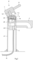
- the sanitary fitting 1 according to the invention shown is similar in its appearance or shape as well as in its operability to a so-called single-lever mixer, as is known in particular as an end-mounted washbasin fitting or kitchen fitting.
- the sanitary fitting 1 has a fitting body 1.1 with a water connection 2, a water outlet 3 and a movable operating element 4 having a lever 4.1.
- the lever 4.1 can be rotated about a first axis of rotation 5, for example a vertical axis of rotation 5, to control the temperature of drinking water to be dispensed and can be tilted about a second axis of rotation 6 or an axis of rotation 6 running transversely to the first axis of rotation 5 to control the water flow, ie the water volume flow to be dispensed (cf. Fig. 3 ).
- the lever 4.1 has a connecting section 4.11 at its end facing away from the fitting body 1.1.
- the connecting section 4.11 serves for the positive and non-positive connection of a complementary operating handle 7.
- the connecting section 4.11 is designed for this purpose, for example, in the form of a square pin.
- the operating handle 7 has a connecting section 7.1 in which a hole 7.11 is formed for the positive reception of the connecting section 4.11 of the lever 4.1.
- the connecting section 7.1 of the operating handle 7 is provided, for example, with a laterally protruding handle lever 8 and preferably has a lateral threaded hole (not shown) into which a grub screw (not shown) pressed against the connecting section 4.11 of the lever 4.1 is screwed.
- the connecting section 7.1 of the operating handle 7 preferably has a collar 7.2 facing the fitting body 1.1, which surrounds an upper or possibly lateral end of the fitting body 1.1 or a hollow screw 9, described in more detail below, which is screwed into an internal thread of the fitting body 1.1.
- the collar 7.2 has a bevel 7.21 on one of its sides, which is designed essentially parallel to a pin or axle body 25 serving to tilt the lever 4.1, which allows a certain tilting movement of the operating handle 7 with the lever 4.1 connected to it, for example a tilting movement of a maximum of approx. 30° (cf. Fig. 1 to 3 ).
- the bevel 7.21 is preferably on the the side of the operating handle 7 facing away from the handle lever 8.
- a handle lever 8 is preferably provided in the sanitary fitting according to the invention.
- the operating handle 7 can be designed as a rotary handle.
- the fitting body 1.1 of the particularly Fig. 2 does not have a mechanical valve for controlling the water flow or for controlling the water temperature. Instead, a sensor device 10 for detecting the respective position of the lever 4.1 relative to a fixed position of the fitting body 1.1 is arranged in the fitting body 1.1 (see in particular Fig. 6 and 7 ).
- the sensor device 10 makes it possible to control an electronic mixing unit 11 arranged remotely from the sanitary fitting 1 by means of the control element 4 (cf. Fig. 1 ).
- This electronic operability gives the user the operating experience of a classic, purely mechanically functioning single-lever mixer and thus the intuitive operation for adjusting the flow rate and temperature of the drinking water to be drawn.
- the mixing unit 11 comprises a connection 12 for cold water, a connection 13 for hot water, a connection 14 for a mixed water pipe 15 that can be connected to the sanitary fitting 1, at least two independently controllable valves 16, 17 for adjusting the temperature or volume flow of the mixed water to be delivered via the connection for the mixed water pipe 15 and drives 18, 19 that control the valves 16, 17.
- the valves 16, 17 are preferably designed using ceramic cartridge technology.
- the respective cartridge-shaped valve 16, 17 has one or more ceramic disks with through holes.
- the drives 18, 19 are preferably formed by electric motors that are connected by gears 20, 21, for example gear or gear-toothed belt gears, to the movable valve bodies (not shown), preferably ceramic disks of the Valves 16, 17 are coupled (cf. Fig. 1 ).
- the mixing unit 11 can be arranged, for example, underneath a washbasin or a kitchen sink.
- the sanitary fitting 1 according to the invention offers the user or operator of a building with corresponding sanitary facilities the option of automated and/or remote-controlled flushing (hygienic flushing) of the water section defined by the sanitary fitting 1 in order to prevent critical drinking water stagnation and thus the risk of legionella formation.
- the mixing unit 11 is preferably incorporated into a drinking water management system of the type mentioned above (not shown in detail here).
- the construction or design of the sanitary fitting 1 according to the invention results in a dead-space-free or at least substantially dead-space-free water path for tapping drinking water as well as for a needs-based hygienic flushing of a drinking water pipe supplying the sanitary fitting 1.
- the sensor device 10 arranged in the fitting body 1.1 preferably has a Hall sensor 10.1.
- the operating element 4 has a rotating body 22 which can be rotated about the first or vertical axis of rotation 5 and which is mounted in a bearing body 23 which can be fixed or is fixed in the fitting body 1.1 (cf. Fig. 2 , 3 and 5 to 8b ).
- the Hall sensor 10.1 is assigned a magnet 24. The magnet 24 is guided in the rotating body 22 so that it can move, whereby the magnet 24 can be moved by a tilting movement of the lever 4.1 (cf. Fig. 2 , 3 and 5 to 8b ).
- the lever 4.1 has a trough-shaped profile 4.12 on its side facing the magnet 24.
- the magnet 24 is preferably designed in the form of a cuboid bar magnet.
- Two guide slots 22.1 in the rotary body 22 hold the magnet 24 in position against rotation on a vertical axis or an axis running parallel to the first axis of rotation 5.
- the Hall sensor 10.1 is mounted on a electronic board 10.2, which is protected in the valve body 1.1 below or spaced from the rotating body 22 ( Fig. 6 and 7 ).
- the rotating body 22 has aligned holes 22.2 in which the pin or axle body 25 is mounted for tilting the lever 4.1. Stops 22.3, 22.4 are formed in the rotating body 22, which limit a tilting movement of the lever 4.1 ( Fig. 8a and 8b ).
- the bearing body 23 has stops 23.1 which limit rotation of the rotating body 22 ( Fig. 9a and 9b ). The stops 23.1 are defined by opposing partial circumferential slots 23.2 formed in the bearing body 23. The ends of the pin or axle body 25 penetrating the lever 4.1 engage with play in the partial circumferential slots 23.2.
- the rotating body 22 and the lever 4.1 of the operating element 4 are provided with friction elements 26, 27.
- the friction elements 26, 27 improve the haptic impression that a user of the sanitary fitting 1 perceives when operating it manually.
- the friction elements 26, 27 or their friction is, for example, dimensioned such that the haptics when manually operating the sanitary fitting 1 according to the invention are similar to the haptics when operating a classic single-lever mixer or even surpass the latter.
- the rotating body 22 is assigned, for example, a clampable or compressible O-ring (elastomer ring) as a friction element 27, while the lever 4.1 has, for example, a bore into which cylinders or balls protruding from it are inserted as friction elements 26.
- the cylinders or balls can be made of elastomer (cf. Fig. 6 and 9a ).
- spring-loaded pressure pieces for example cylindrical or spherical pressure pieces, can be inserted into the bore as friction elements 26.
- the fitting body 1.1 has a partition 1.11 in the form of a wall or a base on the inside, whereby the bearing body 23 is axially fixed to the partition 1.11 with the interposition of a sealing body 28.
- the partition 1.11 there are several blind holes 29 for receiving a corresponding number of Positioning pins 28.1.
- the positioning pins 28.1 are firmly connected to the sealing body 28, for example connected in one piece with it.
- the water connection 2 is also formed in the partition 1.11 in the form of a through hole with an internal thread (cf. Fig. 2 and 4 ).
- the bearing body 23 can be axially fixed or secured in the fitting body 1.1 by means of the hollow screw 9, which is screwed into the internal thread of the fitting body 1.1.
- the hollow screw 9 has a circumferential, radially inward-projecting web 9.1 at its outer end. This web 9.1 additionally axially secures the rotating body 22 in the bearing body 23.
- An electrical and/or signal cable 30 is led through the sealing body 28 to the sensor device 10 in a watertight manner.
- the other end of the electrical and/or signal cable 30 is connected to an electronic unit of the mixing unit 11.
- the cable 30 is used in particular to supply power to the electronic circuit board 10.2.
- one or more lamps 31, preferably light-emitting diodes, are mounted which can emit light of different colors.
- the at least one lamp 31 is a multicolor light-emitting diode.
- the multicolor light-emitting diode there are at least three semiconductor crystals, each of which can generate light in one of the three primary colors red, blue and green. The combination of the light colors red and green results in yellow light; the combination of the light colors red and blue results in magenta; and the combination of the light colors green and blue results in cyan.
- the lamp 31 can light up red, yellow, green or blue depending on the position of the lever 4.1 of the control element 4 in order to signal a setting of hot water, cold water or medium-temperature water.
- the hollow screw 9 is transparent and is preferably surrounded on the outside by a ring-shaped light guide 32.
- the bearing body 23 is preferably also transparent at least in a body section facing the hollow screw 9, wherein this Body section of the bearing body 23 is provided on the inside with an annular light guide 33.
- the light guide 33 is designed such that it defines a deflection surface 33.1, for example a conical deflection surface 33.1 for light rays to be transmitted (cf. Fig. 7 ).
- the sanitary fitting 1 according to the invention can also be designed in the form of a so-called concealed single-lever mixer, in which case a section of the fitting body 1.1 is intended for a concealed arrangement, e.g. a concealed arrangement, and in which the sanitary fitting 1 then has a concealed water outlet instead of a water outlet, on which a connecting bend or the like that is accessible on a surface, e.g. a shower or room wall, can be installed.
Landscapes
- Engineering & Computer Science (AREA)
- Health & Medical Sciences (AREA)
- Life Sciences & Earth Sciences (AREA)
- Hydrology & Water Resources (AREA)
- Public Health (AREA)
- Water Supply & Treatment (AREA)
- General Engineering & Computer Science (AREA)
- Mechanical Engineering (AREA)
- Domestic Plumbing Installations (AREA)
- Multiple-Way Valves (AREA)
Applications Claiming Priority (1)
| Application Number | Priority Date | Filing Date | Title |
|---|---|---|---|
| DE102023115254.8A DE102023115254A1 (de) | 2023-06-12 | 2023-06-12 | Sanitärarmatur und Sanitärarmaturensystem |
Publications (1)
| Publication Number | Publication Date |
|---|---|
| EP4477809A1 true EP4477809A1 (fr) | 2024-12-18 |
Family
ID=91226857
Family Applications (1)
| Application Number | Title | Priority Date | Filing Date |
|---|---|---|---|
| EP24177303.5A Pending EP4477809A1 (fr) | 2023-06-12 | 2024-05-22 | Robinetterie sanitaire et système de robinetterie sanitaire |
Country Status (3)
| Country | Link |
|---|---|
| US (1) | US20240410146A1 (fr) |
| EP (1) | EP4477809A1 (fr) |
| DE (1) | DE102023115254A1 (fr) |
Citations (5)
| Publication number | Priority date | Publication date | Assignee | Title |
|---|---|---|---|---|
| WO2009019731A2 (fr) * | 2007-08-03 | 2009-02-12 | Paolo Andreotti | Dispositif électronique servant à mélanger de l'eau et à réguler le débit |
| AT16285U1 (de) | 2017-03-31 | 2019-05-15 | Wimtec Sanitaerprodukte Gmbh | Endständige Sanitärarmatur mit einer Anordnung zum Spülen |
| EP3929478A1 (fr) * | 2019-02-18 | 2021-12-29 | Sedal, S.L. | Cartouche pour robinet électronique avec capteur magnétique triaxial pour la détection de la position de la commande ou poignée dudit robinet électronique et robinet électronique contenant ladite cartouche |
| EP3933237A2 (fr) * | 2019-02-25 | 2022-01-05 | Sedal, S.L.U. | Cartouche pour robinet électronique ayant une commande d'amplitude de fonctionnement augmentée, robinet électronique qui le contient et méthode de fonctionnement correspondante |
| US11346459B1 (en) * | 2021-01-27 | 2022-05-31 | Harda Intelligent Technologies Co., Ltd. | Inductive switching valve |
Family Cites Families (5)
| Publication number | Priority date | Publication date | Assignee | Title |
|---|---|---|---|---|
| FR2596842B1 (fr) * | 1986-04-08 | 1988-09-16 | Coll Alain | Embouts de robinets sanitaires et douchettes avec indication de temperature |
| US5535779A (en) * | 1994-06-30 | 1996-07-16 | Huang; Lung-Shen | Water outlet control device |
| DE19610620A1 (de) * | 1996-03-19 | 1997-09-25 | Grohe Armaturen Friedrich | Ventilkartuschenanordnung |
| DE102012005062A1 (de) * | 2011-03-15 | 2012-09-20 | Aquis Sanitär AG | Sanitärarmatur mit einem Armaturengehäuse und einer Kontrolleinheit |
| US10450729B2 (en) * | 2017-09-20 | 2019-10-22 | Globe Union Industrial Corp. | Pull-out faucet |
-
2023
- 2023-06-12 DE DE102023115254.8A patent/DE102023115254A1/de active Pending
-
2024
- 2024-05-22 EP EP24177303.5A patent/EP4477809A1/fr active Pending
- 2024-06-11 US US18/739,787 patent/US20240410146A1/en active Pending
Patent Citations (5)
| Publication number | Priority date | Publication date | Assignee | Title |
|---|---|---|---|---|
| WO2009019731A2 (fr) * | 2007-08-03 | 2009-02-12 | Paolo Andreotti | Dispositif électronique servant à mélanger de l'eau et à réguler le débit |
| AT16285U1 (de) | 2017-03-31 | 2019-05-15 | Wimtec Sanitaerprodukte Gmbh | Endständige Sanitärarmatur mit einer Anordnung zum Spülen |
| EP3929478A1 (fr) * | 2019-02-18 | 2021-12-29 | Sedal, S.L. | Cartouche pour robinet électronique avec capteur magnétique triaxial pour la détection de la position de la commande ou poignée dudit robinet électronique et robinet électronique contenant ladite cartouche |
| EP3933237A2 (fr) * | 2019-02-25 | 2022-01-05 | Sedal, S.L.U. | Cartouche pour robinet électronique ayant une commande d'amplitude de fonctionnement augmentée, robinet électronique qui le contient et méthode de fonctionnement correspondante |
| US11346459B1 (en) * | 2021-01-27 | 2022-05-31 | Harda Intelligent Technologies Co., Ltd. | Inductive switching valve |
Also Published As
| Publication number | Publication date |
|---|---|
| DE102023115254A1 (de) | 2024-12-12 |
| US20240410146A1 (en) | 2024-12-12 |
Similar Documents
| Publication | Publication Date | Title |
|---|---|---|
| EP2218840B1 (fr) | Armature sanitaire dotée d'une commande de joystick | |
| EP1895211B1 (fr) | Dispositif de ventilation pour une armature sanitaire et armature sanitaire | |
| DE102013000773A1 (de) | Sanitärarmatur | |
| EP1130177A2 (fr) | Ensemble de soupape sanitaire | |
| EP2331755B1 (fr) | Dispositif de régulation pour orifice d'écoulement d'eau, en particulier d'une plomberie sanitaire | |
| DE60008853T2 (de) | Vorrichtung zur automatischen Wasserabgabe | |
| EP2907929B1 (fr) | Système d'évacuation d'eau et dispositif sanitaire doté d'un système d'évacuation d'eau | |
| CH704188A1 (de) | Ventilloser Armatursockel und ventillose aufsteckbare Armatur. | |
| DE69017176T2 (de) | Mischhahn für warmes/kaltes wasser und seine befestigungsanordnung. | |
| EP1853769B1 (fr) | Système de douche | |
| DE102016100452A1 (de) | Armatur mit Auszugbrause | |
| DE102004014126B3 (de) | Sanitär-Armatur zur Unterputz-Montage | |
| DE102011008804B4 (de) | Sanitärarmatur | |
| DE102013001379A1 (de) | Berührungslos arbeitende elektromotorische Mischbatterie für Kalt- und Warmwasser | |
| EP3533941B1 (fr) | Robinet mélangeur | |
| DE4102134C2 (de) | Berührungslos gesteuerte Sanitärarmatur | |
| EP4477809A1 (fr) | Robinetterie sanitaire et système de robinetterie sanitaire | |
| EP1794377B1 (fr) | Armature sanitaire encastree | |
| DE4102135C2 (de) | Sanitäre Mischarmatur | |
| DE102012100097B4 (de) | Elektronische Sanitärarmatur, insbesondere für Waschtische | |
| WO2018166913A1 (fr) | Unité d'ajustement pour un robinet sanitaire | |
| EP1435480B1 (fr) | Robinetterie sanitaire | |
| EP2169124B1 (fr) | Armature pouvant être commandée électroniquement destinée au mélange d'eau froide et d'eau chaude, notamment pour une table de lavage | |
| EP3460301B1 (fr) | Poignée de thermostat verrouillable pour le rinçage des légionelles | |
| DE102008055713A1 (de) | Einhandmischer zur Aufbau-Montage |
Legal Events
| Date | Code | Title | Description |
|---|---|---|---|
| PUAI | Public reference made under article 153(3) epc to a published international application that has entered the european phase |
Free format text: ORIGINAL CODE: 0009012 |
|
| STAA | Information on the status of an ep patent application or granted ep patent |
Free format text: STATUS: THE APPLICATION HAS BEEN PUBLISHED |
|
| AK | Designated contracting states |
Kind code of ref document: A1 Designated state(s): AL AT BE BG CH CY CZ DE DK EE ES FI FR GB GR HR HU IE IS IT LI LT LU LV MC ME MK MT NL NO PL PT RO RS SE SI SK SM TR |
|
| STAA | Information on the status of an ep patent application or granted ep patent |
Free format text: STATUS: REQUEST FOR EXAMINATION WAS MADE |
|
| 17P | Request for examination filed |
Effective date: 20250612 |
|
| RAP3 | Party data changed (applicant data changed or rights of an application transferred) |
Owner name: VIEGA TECHNOLOGY GMBH & CO. KG |