EP4477858A2 - Refroidisseur intermédiaire de compresseur de moteur à turbine - Google Patents
Refroidisseur intermédiaire de compresseur de moteur à turbine Download PDFInfo
- Publication number
- EP4477858A2 EP4477858A2 EP24182427.5A EP24182427A EP4477858A2 EP 4477858 A2 EP4477858 A2 EP 4477858A2 EP 24182427 A EP24182427 A EP 24182427A EP 4477858 A2 EP4477858 A2 EP 4477858A2
- Authority
- EP
- European Patent Office
- Prior art keywords
- crossflow
- tubes
- leg
- fluid communication
- air passage
- Prior art date
- Legal status (The legal status is an assumption and is not a legal conclusion. Google has not performed a legal analysis and makes no representation as to the accuracy of the status listed.)
- Pending
Links
Images




Classifications
-
- F—MECHANICAL ENGINEERING; LIGHTING; HEATING; WEAPONS; BLASTING
- F02—COMBUSTION ENGINES; HOT-GAS OR COMBUSTION-PRODUCT ENGINE PLANTS
- F02C—GAS-TURBINE PLANTS; AIR INTAKES FOR JET-PROPULSION PLANTS; CONTROLLING FUEL SUPPLY IN AIR-BREATHING JET-PROPULSION PLANTS
- F02C7/00—Features, components parts, details or accessories, not provided for in, or of interest apart form groups F02C1/00 - F02C6/00; Air intakes for jet-propulsion plants
- F02C7/12—Cooling of plants
- F02C7/14—Cooling of plants of fluids in the plant, e.g. lubricant or fuel
- F02C7/141—Cooling of plants of fluids in the plant, e.g. lubricant or fuel of working fluid
-
- F—MECHANICAL ENGINEERING; LIGHTING; HEATING; WEAPONS; BLASTING
- F02—COMBUSTION ENGINES; HOT-GAS OR COMBUSTION-PRODUCT ENGINE PLANTS
- F02C—GAS-TURBINE PLANTS; AIR INTAKES FOR JET-PROPULSION PLANTS; CONTROLLING FUEL SUPPLY IN AIR-BREATHING JET-PROPULSION PLANTS
- F02C3/00—Gas-turbine plants characterised by the use of combustion products as the working fluid
- F02C3/20—Gas-turbine plants characterised by the use of combustion products as the working fluid using a special fuel, oxidant, or dilution fluid to generate the combustion products
- F02C3/22—Gas-turbine plants characterised by the use of combustion products as the working fluid using a special fuel, oxidant, or dilution fluid to generate the combustion products the fuel or oxidant being gaseous at standard temperature and pressure
-
- F—MECHANICAL ENGINEERING; LIGHTING; HEATING; WEAPONS; BLASTING
- F02—COMBUSTION ENGINES; HOT-GAS OR COMBUSTION-PRODUCT ENGINE PLANTS
- F02C—GAS-TURBINE PLANTS; AIR INTAKES FOR JET-PROPULSION PLANTS; CONTROLLING FUEL SUPPLY IN AIR-BREATHING JET-PROPULSION PLANTS
- F02C6/00—Plural gas-turbine plants; Combinations of gas-turbine plants with other apparatus; Adaptations of gas-turbine plants for special use
- F02C6/20—Adaptations of gas-turbine plants for driving vehicles
- F02C6/206—Adaptations of gas-turbine plants for driving vehicles the vehicles being airscrew driven
-
- F—MECHANICAL ENGINEERING; LIGHTING; HEATING; WEAPONS; BLASTING
- F02—COMBUSTION ENGINES; HOT-GAS OR COMBUSTION-PRODUCT ENGINE PLANTS
- F02C—GAS-TURBINE PLANTS; AIR INTAKES FOR JET-PROPULSION PLANTS; CONTROLLING FUEL SUPPLY IN AIR-BREATHING JET-PROPULSION PLANTS
- F02C7/00—Features, components parts, details or accessories, not provided for in, or of interest apart form groups F02C1/00 - F02C6/00; Air intakes for jet-propulsion plants
- F02C7/12—Cooling of plants
- F02C7/14—Cooling of plants of fluids in the plant, e.g. lubricant or fuel
- F02C7/141—Cooling of plants of fluids in the plant, e.g. lubricant or fuel of working fluid
- F02C7/143—Cooling of plants of fluids in the plant, e.g. lubricant or fuel of working fluid before or between the compressor stages
-
- F—MECHANICAL ENGINEERING; LIGHTING; HEATING; WEAPONS; BLASTING
- F02—COMBUSTION ENGINES; HOT-GAS OR COMBUSTION-PRODUCT ENGINE PLANTS
- F02C—GAS-TURBINE PLANTS; AIR INTAKES FOR JET-PROPULSION PLANTS; CONTROLLING FUEL SUPPLY IN AIR-BREATHING JET-PROPULSION PLANTS
- F02C7/00—Features, components parts, details or accessories, not provided for in, or of interest apart form groups F02C1/00 - F02C6/00; Air intakes for jet-propulsion plants
- F02C7/12—Cooling of plants
- F02C7/16—Cooling of plants characterised by cooling medium
-
- F—MECHANICAL ENGINEERING; LIGHTING; HEATING; WEAPONS; BLASTING
- F02—COMBUSTION ENGINES; HOT-GAS OR COMBUSTION-PRODUCT ENGINE PLANTS
- F02C—GAS-TURBINE PLANTS; AIR INTAKES FOR JET-PROPULSION PLANTS; CONTROLLING FUEL SUPPLY IN AIR-BREATHING JET-PROPULSION PLANTS
- F02C7/00—Features, components parts, details or accessories, not provided for in, or of interest apart form groups F02C1/00 - F02C6/00; Air intakes for jet-propulsion plants
- F02C7/22—Fuel supply systems
- F02C7/224—Heating fuel before feeding to the burner
-
- F—MECHANICAL ENGINEERING; LIGHTING; HEATING; WEAPONS; BLASTING
- F02—COMBUSTION ENGINES; HOT-GAS OR COMBUSTION-PRODUCT ENGINE PLANTS
- F02C—GAS-TURBINE PLANTS; AIR INTAKES FOR JET-PROPULSION PLANTS; CONTROLLING FUEL SUPPLY IN AIR-BREATHING JET-PROPULSION PLANTS
- F02C9/00—Controlling gas-turbine plants; Controlling fuel supply in air- breathing jet-propulsion plants
- F02C9/26—Control of fuel supply
- F02C9/40—Control of fuel supply specially adapted to the use of a special fuel or a plurality of fuels
-
- F—MECHANICAL ENGINEERING; LIGHTING; HEATING; WEAPONS; BLASTING
- F05—INDEXING SCHEMES RELATING TO ENGINES OR PUMPS IN VARIOUS SUBCLASSES OF CLASSES F01-F04
- F05D—INDEXING SCHEME FOR ASPECTS RELATING TO NON-POSITIVE-DISPLACEMENT MACHINES OR ENGINES, GAS-TURBINES OR JET-PROPULSION PLANTS
- F05D2260/00—Function
- F05D2260/20—Heat transfer, e.g. cooling
- F05D2260/213—Heat transfer, e.g. cooling by the provision of a heat exchanger within the cooling circuit
-
- F—MECHANICAL ENGINEERING; LIGHTING; HEATING; WEAPONS; BLASTING
- F05—INDEXING SCHEMES RELATING TO ENGINES OR PUMPS IN VARIOUS SUBCLASSES OF CLASSES F01-F04
- F05D—INDEXING SCHEME FOR ASPECTS RELATING TO NON-POSITIVE-DISPLACEMENT MACHINES OR ENGINES, GAS-TURBINES OR JET-PROPULSION PLANTS
- F05D2260/00—Function
- F05D2260/20—Heat transfer, e.g. cooling
- F05D2260/232—Heat transfer, e.g. cooling characterized by the cooling medium
Definitions
- the present disclosure relates to aircraft in general, and to an aircraft turbine engine system with core airflow cooling in particular.
- Turbine engines compress air, add fuel to the compressed air, and combust the air/fuel mixture.
- the combustion products are used to a power one or more turbine sections and in some instances is used to provide motive thrust.
- the aforesaid combustion products create a very high temperature environment that limits the types of materials that can be used in downstream components.
- To mitigate the high temperature environment it is known to use cooling air to cool certain components exposed to the core flow path. The cooling lowers the component temperature and thereby makes it possible to construct the components from a material that has a lower maximum temperature threshold that would be required in the absence of cooling. Hence, there is always a need to improve turbine engine cooling.
- an aircraft propulsion system includes a turbine engine and an intercooler (IC).
- the turbine engine includes a source of non-hydrocarbon fuel, a low pressure compressor (LPC) having an LPC air inlet and an LPC air outlet, a high pressure compressor (HPC) having an HPC air inlet and an HPC air outlet, a combustor section, and a turbine section.
- the intercooler has an IC air inlet, an IC air outlet, a U-shaped air passage, and a plurality of crossflow tubes.
- the IC air inlet is in fluid communication with the LPC air outlet.
- the IC air outlet is in fluid communication with the HPC air inlet.
- the U-shaped air passage is in fluid communication with the IC air inlet and the IC air outlet.
- the crossflow tubes extend through the U-shaped air passage, substantially orthogonal to an airflow encountering the plurality of crossflow tubes within the U-shaped air passage.
- the plurality of crossflow tubes are in fluid communication with the source of non-hydrocarbon fuel, and are configured to contain a flow of the non-hydrocarbon fuel therethrough.
- the U-shaped air passage may include a first leg in fluid communication with the IC air inlet, a second leg in fluid communication with the IC air outlet, and a turn section extending between the first leg and the second leg, wherein the first leg, the turn section, and the second leg are arranged in fluidic series with one another.
- the first leg may be configured to define a first airflow direction within U-shaped air passage
- the second leg may be configured to define a second airflow direction within U-shaped air passage, and the first airflow direction is substantially opposite the second airflow direction.
- At least portions of the first leg and the second leg may be parallel to one another.
- the plurality of crossflow tubes may extend through the first leg, or the second leg, or both.
- the intercooler may further include an inlet manifold in fluid communication with the source of non-hydrocarbon fuel and in fluid communication with the plurality of crossflow tubes.
- the intercooler may further include an outlet manifold in fluid communication with the plurality of crossflow tubes.
- the outlet manifold may be in fluid communication with the combustor.
- the plurality of crossflow tubes may be arranged in an array of rows and columns.
- the plurality of crossflow tubes may be arranged in an aligned configuration.
- the plurality of crossflow tubes may be arranged in a staggered configuration.
- the intercooler may further include a plurality of heat transfer features extending out from one or more of the plurality of crossflow tubes that extend through the first leg, or the second leg, or both.
- the plurality of heat transfer features may be fins aligned with the first airflow direction or the second airflow direction.
- each crossflow tube of the plurality of crossflow tubes has a cross-sectional geometry and all the crossflow tubes in the plurality of crossflow tubes may have the same cross-sectional geometry.
- the plurality of crossflow tubes may have a circular cross-sectional geometry.
- the cross-sectional geometry of the plurality of crossflow tubes may have a length over diameter ratio (L/d) greater than one, and the length of the cross-sectional geometry of the plurality of crossflow tubes may be aligned with a direction of the airflow encountering the plurality of crossflow tubes within the U-shaped air passage.
- the system may further include an inter-compressor duct that extends between the IC air outlet and the HPC air inlet to create the fluid communication therebetween.
- the plurality of crossflow tubes extending through the U-shaped air passage may include crossflow tubes in a serpentine configuration, wherein each crossflow tube serpentine configuration is disposed at a different circumferential position within the intercooler.
- an inter-compressor intercooler for use with a turbine engine that includes a low pressure compressor (LPC) having an LPC air inlet and an LPC air outlet, and a high pressure compressor (HPC) having an HPC air inlet and an HPC air outlet.
- the intercooler includes an intercooler (IC) air inlet, an IC air outlet, a U-shaped air passage, and a plurality of crossflow tubes.
- the IC air inlet is configured for fluid communication with the LPC air outlet.
- the IC air outlet is configured for fluid communication with the HPC air inlet.
- the U-shaped air passage is in fluid communication with the IC air inlet and the IC air outlet.
- the plurality of crossflow tubes extend through the U-shaped air passage, substantially orthogonal to an airflow encountering the plurality of crossflow tubes within the U-shaped air passage.
- the crossflow tubes are in fluid communication with the source of non-hydrocarbon fuel, and are configured to contain a flow of non-hydrocarbon fuel therethrough.
- FIG. 1 diagrammatically illustrates a propulsion system 20 for an aircraft.
- the aircraft may be an airplane, a helicopter, a drone (e.g., an unmanned aerial vehicle (UAV)) or any other manned or unmanned aerial vehicle or system.
- the propulsion system 20 shown in FIG. 1 includes a propulsor rotor 22 and a turbine engine 24.
- Non-limiting examples of a propulsor rotor 22 include a propeller rotor for a turboprop propulsion system, a rotorcraft rotor (e.g., a main helicopter rotor) for a turboshaft propulsion system, a propfan rotor for a propfan propulsion system, a pusher fan rotor for a pusher fan propulsion system, a fan for a turbofan propulsion system, or the like.
- a propeller rotor for a turboprop propulsion system e.g., a main helicopter rotor
- a rotorcraft rotor e.g., a main helicopter rotor
- a propfan rotor for a propfan propulsion system
- a pusher fan rotor for a pusher fan propulsion system
- a fan for a turbofan propulsion system or the like.
- the present disclosure is not limited to any particular propulsor rotor configuration.
- the turbine engine 24 extends axially along an axis 26 between an upstream, forward end 28 and a downstream, aft end 30.
- the turbine engine 24 includes an air inlet 32, a compressor section 34 having a low pressure compressor (LPC) 34A and a high pressure compressor (HPC) 34B, a combustor section 36, and a turbine section 38 having a high pressure turbine (HPT) 38A and a low pressure turbine (LPT) 38B.
- the engine 24 further includes a pair of power turbines 40.
- the LPC 34A and the HPC 34B are shown as centrifugal compressors, but may be axial compressors alternatively.
- annular compressor intercooler 42 is disposed to receive a flow of air pressurized by the LPC 34A and to provide that pressurized airflow to the HPC 34B.
- the engine 24 includes a reduction gearbox 44 that provides drive communication between an engine shaft and the propulsor rotor 22.
- the engine example shown in FIG. 1 is a non-limiting example of a gas turbine engine 24 configuration that may be configured pursuant to aspects of the present disclosure. This example is not intended to be limiting.
- Embodiments of the present disclosure propulsion system 20 may be directed to a turbine engine 24 configured to combust non-hydrocarbon fuels (e.g., hydrogen or "H 2 "), or hydrocarbon fuels (e.g., aviation fuel), or some mixture thereof.
- non-hydrocarbon fuels e.g., hydrogen or "H 2 "
- hydrocarbon fuels e.g., aviation fuel
- the turbine engine 24 within a present disclosure system embodiment may be configured to combust a fuel that is 100% non-hydrocarbon (e.g., 100% H 2 ), or a fuel that is 100% hydrocarbon (e.g., 100% aviation fuel), or a mixture thereof (e.g., a mixture of H 2 and aviation fuel).
- the present disclosure is not limited to any combusting any particular fuel.
- the present disclosure system 20 may include a fuel source 46 configured to store the hydrogen in liquid form.
- the fuel source 46 includes a fuel reservoir and may include a fuel flow regulator.
- the fuel reservoir may be configured to store a quantity of liquid non-hydrocarbon fuel (e.g., liquid H2) and may be configured as an insulated vessel.
- the fuel flow regulator is configured to regulate fuel flow from the fuel reservoir to the turbine engine 24.
- the present disclosure system 20 may use the non-hydrocarbon fuel for one or more different purposes; e.g., act as a coolant, to power a component such as a turboexpander, and the like.
- the description below details how the non-hydrocarbon fuel may be used within a compressor intercooler 42.
- the present disclosure is not limited to using the non-hydrocarbon fuel within a compressor intercooler 42; i.e., the non-hydrocarbon fuel may be used for additional purposes.
- embodiments of the present disclosure include an annular compressor intercooler 42 configured to selectively cool air pressurized by the LPC 34A as it flows between the LPC 34A and the HPC 34B.
- the intercooler 42 includes an intercooler inlet 48 (see FIG. 2 ), an intercooler outlet 50, a U-shaped air passage 52, an inlet manifold 54, an exit manifold 56, and a plurality crossflow tubes 58.
- the intercooler inlet 48 is configured to receive a radial flow of air pressurized by the LPC 34A; i.e., airflow exiting an outlet of the LPC 34A.
- the U-shaped air passage 52 may be an annular body that includes a first leg 52A and a second leg 52B in fluid communication with one another via a turn section 52C.
- the first and second legs 52A, 52B may be substantially parallel to one another and each has an airflow axis that extends therethrough.
- the intercooler inlet 48 is in fluid communication with the first leg 52A.
- the turn section 52C is configured such that air flow from the first leg 52A is turned about 180 degrees and subsequently enters the second leg 52B.
- the second leg 52B is in fluid communication with the intercooler outlet 50.
- the first leg 52A, the turn section 52C, and the second leg 52B may be described as being in a fluidic series arrangement. Referring to FIG.
- an inter-compressor duct 60 extends from the intercooler outlet 50 to an air inlet of the HPC 34B.
- the inter-compressor duct 60 is configured to turn radial airflow exiting the intercooler 42 to an axial flow entering the air inlet of the HPC 34B.
- the intercooler 42 may be described as having a forward side 62 and an aft side 64, opposite the forward side 62.
- the first leg 52A of the U-shaped air passage 52 is disposed adjacent to the forward side 62 and the second leg 52B of the U-shaped air passage 52 is disposed adjacent to the aft side 64.
- the inlet manifold 54 is disposed on the aft side 64 of the intercooler 42 and the exit manifold 56 is disposed on the forward side 62 of the intercooler 42.
- the inlet manifold 54 may be disposed on the forward side 62 of the intercooler 42 and the exit manifold 56 may be disposed on the aft side 66 of the intercooler 42.
- the inlet and exit manifolds 54, 56 each may be an annular structure that extends continuously around the circumference of the intercooler 42, or one or both of the inlet and exit manifolds 54, 56 may include a plurality of manifold segments, with each segment extending a distance circumferentially.
- the inlet manifold 54 includes at least one inlet port 66 that may be configured to receive a flow of non-hydrocarbon fuel directly or indirectly from the fuel source 46.
- the exit manifold 56 includes at least one outlet port 68 that is in fluid communication with the engine fuel system that provides the non-hydrocarbon fuel to the engine 24 for combustion.
- Non-hydrocarbon fuel exiting the intercooler 42 may pass directly to the turbine engine combustor 36, or pass indirectly to the combustor 36 after traversing other system structure; e.g., other cooling structure, or structure that uses the non-hydrocarbon fuel for work, or that converts liquid non-hydrocarbon fuel to gaseous non-hydrocarbon fuel, and the like.
- Each of the crossflow tubes 58 extends between and provides fluid communication between the inlet manifold 54 and the exit manifold 56.
- the crossflow tubes 58 extend through both the first leg 52A and the second leg 52B of the U-shaped air passage 52.
- the crossflow tubes 58 may extend through the first leg 52A or the second leg 52B of the U-shaped air passage 52 but not both.
- FIG. 2 diagrammatically illustrates the crossflow tubes 58 as straight tubes extending through the first leg 52A and the second leg 52B to facilitate the description herein, and the present disclosure is not limited to this crossflow tube 58 configuration.
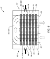
- An example of an alternative crossflow tube 58 configuration is shown in FIGS. 8 and 9 .
- a crossflow tube 58 extends in a serpentine configuration.
- the example shown in FIG. 8 includes crossflow tube segments 58A-G with each pair of adjacent segments fluidically connected to one another by a segment return 74.
- Crossflow tube segment 58A is in fluid communication with the inlet manifold 54 and crossflow tube segment 58G is in fluid communication with the exit manifold 56.
- the serpentine crossflow tube 58 configuration provides a fluid path for non-hydrocarbon fuel that extends from the inlet manifold 54, sequentially through the crossflow tube segments 58A-58G, and into the exit manifold 56.
- the intercooler 42 may include a plurality of serpentine crossflow tube 58 configurations spaced apart from one another around the circumference of the annular intercooler 42.
- FIG. 9 diagrammatically illustrates serpentine crossflow tube 58 configurations circumferentially spaced apart from one another; e.g., disposed at a first circumferential position (CP1), at a second circumferential position (CP2), at a third circumferential position (CP3), and so on.
- the crossflow tube 58 embodiments detailed above are examples of possible tube configurations and the present disclosure is not limited to these examples.
- FIG. 3 diagrammatically illustrates an array of crossflow tubes 58 disposed in aligned rows and columns.
- FIG. 4 diagrammatically illustrates an array of crossflow tubes 58 wherein the crossflow tubes 58 disposed in adjacent rows are staggered.
- the arrow diagrammatically illustrates the airflow through the U-shaped air passage 52 substantially orthogonal to the crossflow tubes 58.
- the crossflow tube 58 arrangements shown in FIGS. 3 and 4 are examples of how an array of crossflow tubes 58. The present disclosure is not limited to any particular crossflow tube 58 arrangement.
- inlet and exit manifolds 54, 56 disposed on opposite sides of the intercooler 42.
- the present disclosure is not limited to this embodiment.
- other structure may be disposed on opposite sides of the intercooler 42 to provide and receive the non-hydrocarbon fuel passing through the crossflow tubes 58.
- the present disclosure is described above as having a plurality of crossflow tubes 58 (shown as circular) extending through the U-shaped air passage 52.
- the crossflow tubes 58 may have an LID greater than one, with the LID oriented so that the passing airflow travels along the longer L length extending through the U-shaped air passage 52.
- the present disclosure as described and diagrammatically shown in the FIGS. 3 and 4 shows all the crossflow tubes 58 having the same cross-sectional geometry.
- the present disclosure is not limited to these examples; e.g., the crossflow tubes 58 are not limited to any particular cross-sectional geometry, and more than one crossflow tube cross-sectional geometry may be used.
- the present disclosure intercooler 42 may include heat transfer features 70 in communication with the crossflow tubes 58, positioned to engage with the air flow passing through the U-shaped air passage 52.
- heat transfer features 70 include pins, fins, and the like extending out from the respective crossflow tubes 58.
- the heat transfer features 70 may be disposed on the portions of the crossflow tubes 58 in the first leg 52A of the U-shaped air passage 52, or disposed on the portions of the crossflow tubes 58 in the second leg 52B of the U-shaped air passage 52, or both.
- FIG. 6 illustrates fins 70 extending generally parallel to the airflow direction within both the first and second legs 52A, 52B of the U-shaped air passage 52.
- the present disclosure intercooler 42 may include vanes 72 disposed upstream of the first leg 52A of the U-shaped air passage 52 to orient the air flow entering the intercooler 42 in a desirable manner.
- the vanes 72 may be configured to guide the airflow, or to diffuse the airflow, or the like, or any combination thereof.
- the present disclosure is not limited to any particular vane 72 orientation or configuration.
- propulsion system 20 air is drawn into the engine air inlet 32 and is passed to the LPC 34A.
- the air is worked within the LPC 34A to a higher pressure and temperature and is passed from the LPC 34A to the intercooler 42 prior to entering the HPC 34B. More specifically the air enters the intercooler inlet 48 and passes into the first leg 52A of the U-shaped air passage 52.
- the airflow passes through the vanes 72 prior to passing into the first leg 52A of the U-shaped air passage 52.
- Airflow passing through the first leg 52A of the U-shaped air passage 52 travels in a first direction (e.g., in an outer radial direction). Airflow passing through the second leg 52B of the U-shaped air passage 52 travels in a second direction (e.g., in an inner radial direction), opposite the first direction. As the airflow passes through the first leg 52A of the U-shaped air passage 52, the airflow will contact and traverse the portion of the crossflow tubes 58 extending through the first leg 52A. From there, the airflow passes through the turn section 52C of the U-shaped air passage 52 and is directed into the second leg 52B of the U-shaped air passage 52.
- the passage of the airflow through the turn section 52C turns the airflow about 180 degrees, causing the airflow to exit the turn section 52C in a direction that is substantially opposite the direction it entered the turn section 52C.
- the airflow will contact and traverse another portion of the crossflow tubes 58 that extend through the second leg 52B. From there, the airflow enters the inter-compressor duct 60 and passes to the HPC 34B.
- a flow of fuel is provided to the inlet manifold 54.
- the flow of fuel provided to the intercooler 42 may be a liquid non-hydrocarbon fuel provided by the fuel source 46, or alternatively the fuel may be in a gaseous state.
- the inlet manifold 54 distributes the fuel to the crossflow tubes 58. The fuel passes through the crossflow tubes 58, enters and passes through the exit manifold 56, and is subsequently directly or indirectly provided to the engine combustor 36.
- the fuel passing through the crossflow tubes 58 in a direction orthogonal to the airflow through the U-shaped air passage 52 creates heat transfer between the two fluids; i.e., the compressed air is cooled and the fuel is heated.
- the fuel may be heated sufficiently to change the state of the non-hydrocarbon fuel from a liquid state to a gaseous state. Elevating the temperature of the airflow prior to the airflow entering the HPC has the benefit of decreasing the thermal requirements downstream of the intercooler 42 (e.g., in the HPC 34B, combustor 36, and the like) and potentially increasing the efficiency of the engine 24.
- the embodiments may be described as a process which is depicted as a flowchart, a flow diagram, a block diagram, etc. Although any one of these structures may describe the operations as a sequential process, many of the operations can be performed in parallel or concurrently. In addition, the order of the operations may be rearranged. A process may correspond to a method, a function, a procedure, a subroutine, a subprogram, etc.
- the singular forms "a,” “an,” and “the” refer to one or more than one, unless the context clearly dictates otherwise.
- the term “comprising a specimen” includes single or plural specimens and is considered equivalent to the phrase “comprising at least one specimen.”
- the term “or” refers to a single element of stated alternative elements or a combination of two or more elements unless the context clearly indicates otherwise.
- “comprises” means “includes.”
- “comprising A or B,” means “including A or B, or A and B,” without excluding additional elements.
Landscapes
- Engineering & Computer Science (AREA)
- Chemical & Material Sciences (AREA)
- Combustion & Propulsion (AREA)
- Mechanical Engineering (AREA)
- General Engineering & Computer Science (AREA)
- Heat-Exchange Devices With Radiators And Conduit Assemblies (AREA)
- Jet Pumps And Other Pumps (AREA)
Applications Claiming Priority (1)
| Application Number | Priority Date | Filing Date | Title |
|---|---|---|---|
| US18/211,133 US12209535B2 (en) | 2023-06-16 | 2023-06-16 | Turbine engine compressor intercooler |
Publications (2)
| Publication Number | Publication Date |
|---|---|
| EP4477858A2 true EP4477858A2 (fr) | 2024-12-18 |
| EP4477858A3 EP4477858A3 (fr) | 2025-03-26 |
Family
ID=91581053
Family Applications (1)
| Application Number | Title | Priority Date | Filing Date |
|---|---|---|---|
| EP24182427.5A Pending EP4477858A3 (fr) | 2023-06-16 | 2024-06-14 | Refroidisseur intermédiaire de compresseur de moteur à turbine |
Country Status (3)
| Country | Link |
|---|---|
| US (1) | US12209535B2 (fr) |
| EP (1) | EP4477858A3 (fr) |
| CA (1) | CA3241476A1 (fr) |
Families Citing this family (1)
| Publication number | Priority date | Publication date | Assignee | Title |
|---|---|---|---|---|
| US12359623B1 (en) * | 2024-04-09 | 2025-07-15 | Pratt & Whitney Canada Corp. | Hydrogen turboexpander for use in an aviation propulsion system |
Family Cites Families (13)
| Publication number | Priority date | Publication date | Assignee | Title |
|---|---|---|---|---|
| US2960825A (en) * | 1955-10-19 | 1960-11-22 | Thompson Ramo Wooldridge Inc | Reexpansion gas turbine engine with differential compressor drive |
| DE1020835B (de) * | 1956-03-29 | 1957-12-12 | Tech Studien Ag | Maschinengruppe einer Gasturbinenanlage |
| US3486340A (en) * | 1967-05-05 | 1969-12-30 | Garrett Corp | Gas turbine powerplant with means for cooling compressed air |
| WO1995011376A1 (fr) * | 1993-10-19 | 1995-04-27 | State Of California Energy Resources Conservation And Development Commission | Centrale thermique a turbine a gaz a performances ameliorees |
| US8069905B2 (en) * | 2003-06-11 | 2011-12-06 | Usui Kokusai Sangyo Kaisha Limited | EGR gas cooling device |
| GB2413366B (en) * | 2004-04-24 | 2006-09-13 | Rolls Royce Plc | Engine. |
| US8137075B2 (en) | 2007-08-31 | 2012-03-20 | Honeywell International Inc. | Compressor impellers, compressor sections including the compressor impellers, and methods of manufacturing |
| US9752585B2 (en) * | 2013-03-15 | 2017-09-05 | United Technologies Corporation | Gas turbine engine architecture with intercooled twin centrifugal compressor |
| US10823070B2 (en) | 2017-01-20 | 2020-11-03 | Raytheon Technologies Corporation | Intercooled cooling air system with bypass |
| US11542869B2 (en) | 2021-05-27 | 2023-01-03 | Pratt & Whitney Canada Corp. | Dual cycle intercooled hydrogen engine architecture |
| US20230022809A1 (en) | 2021-07-22 | 2023-01-26 | Pratt & Whitney Canada Corp. | Dual cycle intercooled engine architectures |
| US11619170B1 (en) | 2022-03-07 | 2023-04-04 | Rolls-Royce North American Technologies Inc. | Gas turbine engine with radial turbine having modulated fuel cooled cooling air |
| US12044171B1 (en) * | 2023-02-10 | 2024-07-23 | Rtx Corporation | Engine with intercooler |
-
2023
- 2023-06-16 US US18/211,133 patent/US12209535B2/en active Active
-
2024
- 2024-06-11 CA CA3241476A patent/CA3241476A1/en active Pending
- 2024-06-14 EP EP24182427.5A patent/EP4477858A3/fr active Pending
Also Published As
| Publication number | Publication date |
|---|---|
| US12209535B2 (en) | 2025-01-28 |
| EP4477858A3 (fr) | 2025-03-26 |
| US20240418126A1 (en) | 2024-12-19 |
| CA3241476A1 (en) | 2025-06-09 |
Similar Documents
| Publication | Publication Date | Title |
|---|---|---|
| US10400675B2 (en) | Closed loop cooling method and system with heat pipes for a gas turbine engine | |
| US20220018262A1 (en) | Mechanically driven air vehicle thermal management device | |
| EP3176408A1 (fr) | Système et procédé de refroidissement intermédiaire pour un moteur à turbine à gaz | |
| US10823067B2 (en) | System for a surface cooler with OGV oriented fin angles | |
| EP3187684A1 (fr) | Système et procédé de réduction des températures moteur après arrêt | |
| EP3176409A1 (fr) | Procédé de refroidissement en circuit fermé pour une turbomachine | |
| CN115217634A (zh) | 飞行器热传输系统和方法 | |
| EP4477858A2 (fr) | Refroidisseur intermédiaire de compresseur de moteur à turbine | |
| EP4477856A2 (fr) | Moteur à turbine à gaz avec système de récupération d'eau | |
| EP4484725A1 (fr) | Système de propulsion d'aéronef avec échangeur de chaleur d'échappement de moteur à turbine | |
| EP4477857A1 (fr) | Moteur à turbine à gaz avec système de carburant à hydrogène | |
| EP4481173A1 (fr) | Système de propulsion d'aéronef avec moteur à turbine et condenseur d'échappement | |
| EP4477860A1 (fr) | Système et procédé de refroidissement de composant de turbine de moteur à turbine | |
| EP4477855A2 (fr) | Système de moteur à turbine à gaz avec turbine entraînée par carburant | |
| US12077311B1 (en) | Aircraft propulsion system with turbine engine and exhaust condenser | |
| US11905837B2 (en) | Sealing system including a seal assembly between components | |
| US20260078716A1 (en) | Internally diffusing heat exchanger for a gas turbine engine | |
| EP4726188A2 (fr) | Cycle de récupération amélioré pour moteur de turbine d'une centrale d'aéronef |
Legal Events
| Date | Code | Title | Description |
|---|---|---|---|
| PUAI | Public reference made under article 153(3) epc to a published international application that has entered the european phase |
Free format text: ORIGINAL CODE: 0009012 |
|
| STAA | Information on the status of an ep patent application or granted ep patent |
Free format text: STATUS: THE APPLICATION HAS BEEN PUBLISHED |
|
| AK | Designated contracting states |
Kind code of ref document: A2 Designated state(s): AL AT BE BG CH CY CZ DE DK EE ES FI FR GB GR HR HU IE IS IT LI LT LU LV MC ME MK MT NL NO PL PT RO RS SE SI SK SM TR |
|
| PUAL | Search report despatched |
Free format text: ORIGINAL CODE: 0009013 |
|
| AK | Designated contracting states |
Kind code of ref document: A3 Designated state(s): AL AT BE BG CH CY CZ DE DK EE ES FI FR GB GR HR HU IE IS IT LI LT LU LV MC ME MK MT NL NO PL PT RO RS SE SI SK SM TR |
|
| RIC1 | Information provided on ipc code assigned before grant |
Ipc: F02C 7/224 20060101ALI20250220BHEP Ipc: F02C 7/143 20060101ALI20250220BHEP Ipc: F02C 3/22 20060101AFI20250220BHEP |
|
| STAA | Information on the status of an ep patent application or granted ep patent |
Free format text: STATUS: REQUEST FOR EXAMINATION WAS MADE |
|
| 17P | Request for examination filed |
Effective date: 20250926 |