EP4477875A1 - Energieerzeugungsanlage mit windturbinen verschiedener grösse - Google Patents
Energieerzeugungsanlage mit windturbinen verschiedener grösse Download PDFInfo
- Publication number
- EP4477875A1 EP4477875A1 EP24181601.6A EP24181601A EP4477875A1 EP 4477875 A1 EP4477875 A1 EP 4477875A1 EP 24181601 A EP24181601 A EP 24181601A EP 4477875 A1 EP4477875 A1 EP 4477875A1
- Authority
- EP
- European Patent Office
- Prior art keywords
- type
- wind turbines
- energy production
- production site
- type wind
- Prior art date
- Legal status (The legal status is an assumption and is not a legal conclusion. Google has not performed a legal analysis and makes no representation as to the accuracy of the status listed.)
- Withdrawn
Links
Images


Classifications
-
- F—MECHANICAL ENGINEERING; LIGHTING; HEATING; WEAPONS; BLASTING
- F03—MACHINES OR ENGINES FOR LIQUIDS; WIND, SPRING, OR WEIGHT MOTORS; PRODUCING MECHANICAL POWER OR A REACTIVE PROPULSIVE THRUST, NOT OTHERWISE PROVIDED FOR
- F03D—WIND MOTORS
- F03D9/00—Adaptations of wind motors for special use; Combinations of wind motors with apparatus driven thereby; Wind motors specially adapted for installation in particular locations
- F03D9/20—Wind motors characterised by the driven apparatus
- F03D9/25—Wind motors characterised by the driven apparatus the apparatus being an electrical generator
- F03D9/255—Wind motors characterised by the driven apparatus the apparatus being an electrical generator connected to electrical distribution networks; Arrangements therefor
- F03D9/257—Wind motors characterised by the driven apparatus the apparatus being an electrical generator connected to electrical distribution networks; Arrangements therefor the wind motor being part of a wind farm
-
- F—MECHANICAL ENGINEERING; LIGHTING; HEATING; WEAPONS; BLASTING
- F03—MACHINES OR ENGINES FOR LIQUIDS; WIND, SPRING, OR WEIGHT MOTORS; PRODUCING MECHANICAL POWER OR A REACTIVE PROPULSIVE THRUST, NOT OTHERWISE PROVIDED FOR
- F03D—WIND MOTORS
- F03D13/00—Assembly, mounting or commissioning of wind motors; Arrangements specially adapted for transporting wind motor components
- F03D13/20—Arrangements for mounting or supporting wind motors; Masts or towers for wind motors
-
- F—MECHANICAL ENGINEERING; LIGHTING; HEATING; WEAPONS; BLASTING
- F05—INDEXING SCHEMES RELATING TO ENGINES OR PUMPS IN VARIOUS SUBCLASSES OF CLASSES F01-F04
- F05B—INDEXING SCHEME RELATING TO WIND, SPRING, WEIGHT, INERTIA OR LIKE MOTORS, TO MACHINES OR ENGINES FOR LIQUIDS COVERED BY SUBCLASSES F03B, F03D AND F03G
- F05B2220/00—Application
- F05B2220/61—Application for hydrogen and/or oxygen production
-
- F—MECHANICAL ENGINEERING; LIGHTING; HEATING; WEAPONS; BLASTING
- F05—INDEXING SCHEMES RELATING TO ENGINES OR PUMPS IN VARIOUS SUBCLASSES OF CLASSES F01-F04
- F05B—INDEXING SCHEME RELATING TO WIND, SPRING, WEIGHT, INERTIA OR LIKE MOTORS, TO MACHINES OR ENGINES FOR LIQUIDS COVERED BY SUBCLASSES F03B, F03D AND F03G
- F05B2240/00—Components
- F05B2240/90—Mounting on supporting structures or systems
- F05B2240/95—Mounting on supporting structures or systems offshore
-
- Y—GENERAL TAGGING OF NEW TECHNOLOGICAL DEVELOPMENTS; GENERAL TAGGING OF CROSS-SECTIONAL TECHNOLOGIES SPANNING OVER SEVERAL SECTIONS OF THE IPC; TECHNICAL SUBJECTS COVERED BY FORMER USPC CROSS-REFERENCE ART COLLECTIONS [XRACs] AND DIGESTS
- Y02—TECHNOLOGIES OR APPLICATIONS FOR MITIGATION OR ADAPTATION AGAINST CLIMATE CHANGE
- Y02E—REDUCTION OF GREENHOUSE GAS [GHG] EMISSIONS, RELATED TO ENERGY GENERATION, TRANSMISSION OR DISTRIBUTION
- Y02E10/00—Energy generation through renewable energy sources
- Y02E10/70—Wind energy
- Y02E10/72—Wind turbines with rotation axis in wind direction
-
- Y—GENERAL TAGGING OF NEW TECHNOLOGICAL DEVELOPMENTS; GENERAL TAGGING OF CROSS-SECTIONAL TECHNOLOGIES SPANNING OVER SEVERAL SECTIONS OF THE IPC; TECHNICAL SUBJECTS COVERED BY FORMER USPC CROSS-REFERENCE ART COLLECTIONS [XRACs] AND DIGESTS
- Y02—TECHNOLOGIES OR APPLICATIONS FOR MITIGATION OR ADAPTATION AGAINST CLIMATE CHANGE
- Y02E—REDUCTION OF GREENHOUSE GAS [GHG] EMISSIONS, RELATED TO ENERGY GENERATION, TRANSMISSION OR DISTRIBUTION
- Y02E10/00—Energy generation through renewable energy sources
- Y02E10/70—Wind energy
- Y02E10/727—Offshore wind turbines
Definitions
- the present invention relates to an energy site comprising wind turbines of a least two different sizes, more particularly to an energy production site configuration and methods, in which the energy extraction capacity per unit area is increased compared to energy sites known in the art.
- a need for better utilisation of an area, which is allocated for an energy production site, can also exist if, for instance for geographical or transportation related reasons, it is not possible to install many and big enough wind turbines within the area to utilise the nominal power rating of the energy transmission line available for the energy production site.
- the present invention relates to an energy production site comprising a plurality of first type wind turbines and a plurality of second type wind turbines, wherein the first type wind turbines and the second type wind turbines are horizontal axis wind turbines, wherein each of the first type wind turbines comprises a nacelle mounted on a first type tower, a first type rotor comprising one or more first type wind turbine blades describing a first rotor diameter, and an electrical generator driven by the first type rotor for converting rotation thereof into electrical power, wherein each of the second type wind turbines comprises a nacelle mounted on a second type tower, a second type rotor comprising one or more second type wind turbine blades describing a second rotor diameter, and an electrical generator driven by the second type rotor for converting rotation thereof into electrical power, wherein the axes of rotation of the second type rotors are positioned lower than the axes of rotation of the first type rotors and the second rotor diameter is smaller than the first rotor
- the energy extraction capacity from the energy production site can be increased significantly, because the second type wind turbines can produce energy without significantly influencing the energy production of the first type wind turbines.
- the second type wind turbines are smaller than the first type wind turbines, the addition of the second type wind turbines has only limited impact on the turbulence and wake effects on the site. The difference in height means that the interference of the smaller wind turbines on the larger ones is limited.
- wind turbines are suitably distributed between each other so that the integrity of both types of wind turbines is maintained, an increase of up to 40% of the installed capacity of the energy production site compared to an energy production site occupying the same area but comprising only the first type wind turbines may be obtained.
- the type of the towers should be understood to include the height as well as the structure and all other features of the tower.
- the first and second type of tower can have the same or different structures, and they can belong to different IEC classes. This also means, for instance, that one or both types of towers may be configured to be supported by a floating foundation.
- the second rotor diameter being smaller than the first rotor diameter means that the rated maximum power output of the second type wind turbines is smaller, such as at least 20%, for example at least 30% or at least 50% smaller, than the rated maximum power output of the first type wind turbines.
- the energy production site is an offshore energy production site.
- the present invention is particularly suited for offshore installation. However, it could also find use on onshore energy production sites, where the conditions are suitable.
- the first type wind turbines and the second type wind turbines are of different types, such as being produced by different manufacturers, being controlled by different types of control systems, being originally produced as onshore and offshore wind turbines, respectively, etc.
- the first type wind turbines are preferably of a type that would be chosen for optimising the energy production of the energy production site, if it had only comprises these first type wind turbines
- the second type wind turbines can be of a less expensive type, such as older models and types, which are no longer "state-of-the-art". Even “second-hand" wind turbines, which have previously been used at other energy production sites, can be used as second type wind turbines in an energy production site according to the present invention. Also, onshore wind turbines, which typically have a higher production volume and therefore are more cost competitive, can be used as second type wind turbines in an offshore energy production site according to the present invention.
- the second rotor diameter is less than 60%, such as less than 55%, such as less than 50%, of the first rotor diameter.
- the second rotor diameter must be significantly smaller than the first rotor diameter, such as about half the size of the first rotor diameter.
- the second rotor diameter is between 40% and 60%, preferably between 45% and 55%, most preferred 50%, of the first rotor diameter.
- the energy production site is an offshore site
- the first type wind turbines and the second type wind turbines are arranged in such a way that the difference between the average height over the sea level of the lowest point of the first type rotors and the average height over the sea level of the lowest point of the second type rotors is less than 20%, preferably less than 10%, most preferred less than 5% of the second rotor diameter, the average height being measured over time.
- the first type wind turbines are positioned in such a way that the horizontal centre-to-centre distance between two neighbouring first type towers is between 3 and 10 times the first rotor diameter.
- the second type wind turbines are positioned in such a way that the horizontal centre-to-centre distance between any second type tower and the nearest first type tower or the nearest second type tower is between 3 and 10 times the second rotor diameter.
- the first type wind turbines constitute a first wind park and the second type wind turbines constitute a second wind park.
- the energy production site comprises two wind parks, which geographically coincide or at least overlap each other significantly.
- the first wind park and/or the second wind park further comprises an electrolyser arrangement for production of hydrogen using electrical power from the electrical generators of the wind turbines of that wind park, a hydrogen storage arrangement for storing hydrogen produced by the electrolyser arrangement, and one of the first wind park and the second wind park primarily generates electrical power to be directly transmitted to a utility grid, whereas the other one of the first wind park and the second wind park primarily generates hydrogen.
- the produced hydrogen can be stored for later conversion to electrical power and transmission to a utility grid and/or it can be stored for shipping or collected by pipe for storing or export. It may also be processed locally or centrally, for instance for producing ammonia.
- one of the first wind park and the second wind park comprises an electrolyser arrangement configured to consume at least 30%, such as at least 50% of the maximum rated power output of that wind park, and the other one of the first wind park and the second wind park comprises no electrolyser arrangement or comprises an electrolyser arrangement configured to consume less than 20%, such as less than 10% of the maximum rated power output of that wind park.
- At least one of the first wind park and the second wind park which comprises a hydrogen storage arrangement, also comprises an electrical power generation arrangement for converting the stored hydrogen into electrical power.
- the first wind park and the second wind park use a common power transmission line for transmitting electrical power to a utility grid.
- the first wind park and the second wind park use different power transmission lines for transmitting electrical power to the same utility electrical grid or to different utility grids.
- the first wind park and the second wind park are operated independently from one another, such as by different park operators or by different park control systems.
- Electric power produced by the first and the second wind park may be transmitted to the same or to different utility grids using a common or two separate transmission lines. If, for instance, the wind parks are operated by different park operators, it may be desired to operate the parks independently from each other and/or to transmit the produced electric power to different utility grids.
- utility grids with different points of connection for instance in different countries, utility grids with different ownership and utility grids with different electrical systems.
- the operation of the first wind park and the second wind park, respectively is coordinated, e.g. by pitching and/or yawing or even idling one or more wind turbines, for instance so that the production of one of the first wind park and the second wind park may be prioritised over the production of the other one of the first wind park and the second wind park, based on wind conditions, electricity prices, etc.
- the production can be prioritised in a number of different ways, such as
- the energy production site further comprises a plurality of third type wind turbines
- the third type wind turbines are horizontal axis wind turbines
- each of the third type wind turbine comprises a nacelle mounted on a third type tower, a third type rotor comprising one or more third type wind turbine blades describing a third rotor diameter, and an electrical generator driven by the third type rotor for converting rotation thereof into electrical power
- the axes of rotation of the third type rotors are positioned lower than the axes of rotation of the second type towers and the third rotor diameter is smaller than the second rotor diameter
- the third type wind turbines are distributed between the first type wind turbines and/or the second type wind turbines across at least a part of the area of the energy production site.
- the energy extraction capacity from the energy production site can be increased even further, such as to more than the double of the capacity of the first type wind turbines alone, because it is possible to add a significant number of third type wind turbines between the first type wind turbines and the second type wind turbines without significantly influencing the energy production thereof.
- the third rotor diameter being smaller than the second rotor diameter means that the rated maximum power output of the third type wind turbines is smaller, such as at least 20%, for example at least 30% or at least 50% smaller, than the rated maximum power output of the second type wind turbines.
- a third wind park constituted by the third type wind turbines can vary in a number of ways and combined with the configurations, control and operation of the first wind park and the second wind park in many ways, similar to what is described above for the first wind park and the second wind park in an energy production site with only two wind parks.
- the third rotor diameter is less than 60%, such as less than 55%, such as less than 50%, of the second rotor diameter.
- the third rotor diameter must be significantly smaller than the second rotor diameter, such as about half the size of the second rotor diameter.
- the third rotor diameter is between 40% and 60%, preferably between 45% and 55%, most preferred 50%, of the second rotor diameter.
- the energy production site is an offshore site
- the third type wind turbines are arranged in such a way that the difference between the average height over the sea level of the lowest point of the second type rotors and the average height over the sea level of the lowest point of the third type rotors is less than 20%, preferably less than 10%, most preferred less than 5% of the third rotor diameter, the average height being measured over time.
- the third type wind turbines are positioned in such a way that the horizontal centre-to-centre distance between any third type tower and the nearest first type tower, the nearest second type tower or the nearest third type tower is between 3 and 10 times the third rotor diameter.
- it in another aspect of the invention, relates to a method for increasing energy extraction capacity utilising an energy production site, which method comprises the steps of installing a plurality of first type wind turbines at the energy production site, and installing a plurality of second type wind turbines at the energy production site, wherein the first type wind turbines and the second type wind turbines are distributed across the area of the energy production site between each other, so that an energy production site as described above is obtained.
- This aspect of the invention relates to the establishing of an energy production site as described above, in which the first type wind turbines and the second type wind turbines are both present from the beginning.
- the method further comprises the step of installing a plurality of third type wind turbines at the energy production site, wherein the third type wind turbines are distributed across the area of the energy production site between the first type wind turbines and the second type wind turbines, so that an energy production site as described above is obtained.
- the step of installing the third type wind turbines can be performed simultaneously with or sometime later than the step of installing the first type wind turbines and the second type wind turbines.
- it relates to a method for increasing the energy extraction capacity from an existing energy production site comprising a plurality of first type wind turbines distributed across the area of the energy production site, which method comprises the step of installing a plurality of second type wind turbines at the energy production site, wherein the second type wind turbines are distributed across the area of the energy production site between the first type wind turbines, so that an energy production site as described above is obtained.
- This aspect of the invention relates to the retrofitting of an energy production comprising a first type wind turbines with a second type wind turbines for obtaining an energy production site as described above.
- the method further comprises the step of installing a plurality of third type wind turbines at the energy production site, wherein the third type wind turbines are distributed across the area of the energy production site between the first type wind turbines and the second type wind turbines, so that an energy production site as described above is obtained.
- the step of installing the third type wind turbines can be performed simultaneously with or sometime later than the step of installing the second type wind turbines.
- Fig. 1 shows a schematic layout of an energy production site 1 as known within the art, comprising a plurality of first type wind turbines 2.
- the first type wind turbines 2 are arranged in straight lines forming a two-dimensional array, the distance D between any of the first type wind turbines 2 and it closest neighbouring first type wind turbine 2 being the same in both dimensions of this array.
- this simplicity of the illustrated layout is merely chosen for the sake of clarity and that, as it will be known to the person skilled in the art, the first type wind turbines 2 may be distributed or scattered across the energy production site 1 in a various number of different ways and patterns, often depending on the landscape if the energy production site 1 is an onshore site 1.
- Fig. 2 is a schematic front view of some first type wind turbines 2 of the energy production site 1 shown in Fig. 1 . It illustrates that the first type wind turbines 2 are horizontal axis wind turbines comprising a first type tower 3 and a first type rotor 4. Fig. 7 shows how the first type rotor 4 describes a first rotor diameter RD1. Fig. 2 further illustrates that the distance D between two neighbouring first type wind turbines 2 is defined as the horizontal centre-to-centre distance D between two neighbouring first type towers 3.
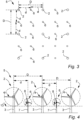
- Fig. 3 shows a schematic layout of an energy production site 5 according to an embodiment of the invention, comprising two different types of wind turbines 2, 6.
- a plurality of first type wind turbines 2 are arranged in a two-dimensional array like in Fig. 1
- a plurality of second type wind turbines 6 are arranged in between the first type wind turbines 2 in such a way that the distance d between any of the second type wind turbines 6 and its closest neighbouring first type wind turbine 2 or second type wind turbine 6 is the same in both dimensions of this array.
- the simplicity of the illustrated layout of the energy production site 5 is merely chosen for the sake of clarity and that the first type wind turbines 2 and the second type wind turbines 6 may be distributed or scattered across the energy production site 5 in a various number of different ways and patterns.
- the important thing is not that the distance d to neighbouring wind turbines 2, 6 is the same in all directions, but that the distance d to each of the neighbouring wind turbines 2, 6 is sufficient to avoid significant disturbances in the form of turbulence, wake effects, shadow effects and the like.
- Fig. 4 is a schematic front view of some first type wind turbines 2 and some second type wind turbines 6 of the energy production site 5 shown in Fig. 3 . It illustrates that also the second type wind turbines 6 are horizontal axis wind turbines comprising a second type tower 7 and a second type rotor 8. Fig. 7 shows how the second type rotor 8 describes a second rotor diameter RD2. Fig. 4 further illustrates that the distance d between a second type wind turbine 6 and a neighbouring first type wind turbine 2 or second type wind turbine 6 is defined as the horizontal centre-to-centre distance d between the towers 3, 7 of the two wind turbines 2, 6 in question.
- Fig. 5 shows a schematic layout of an energy production site 9 according to an embodiment of the invention, comprising tree different types of wind turbines (2, 6, 10).
- a plurality of first type wind turbines 2 and second type wind turbines 6 are arranged in a two-dimensional array like in Fig. 3
- a plurality of third type wind turbines 10 are arranged in between the first type wind turbines 2 and the second type wind turbines 6 in such a way that the distance d' between any of the third type wind turbines 10 and its closest neighbouring first type wind turbine 2, second type wind turbine 6 or third type wind turbine 10 is the same in both dimensions of this array.
- the simplicity of the illustrated layout of the energy production site 9 is merely chosen for the sake of clarity and that the first type wind turbines 2, the second type wind turbines 6 and the third type wind turbines 10 may be distributed or scattered across the energy production site 9 in a various number of different ways and patterns.
- the important thing is not that the distance d' to neighbouring wind turbines 2, 6, 10 is the same in all directions, but that the distance d' to each of the neighbouring wind turbines 2, 6, 10 is sufficient to avoid significant disturbances in the form of turbulence, wake effects, shadow effects and the like.
- Fig. 6 is a schematic front view of some first type wind turbines 2, some second type wind turbines 6 and some third type wind turbines 10 of the energy production site 9 shown in Fig. 5 . It illustrates that also the third type wind turbines 10 are also horizontal axis wind turbines comprising a third type tower 11 and a third type rotor 12. Fig. 7 shows how the third type rotor 12 describes a third rotor diameter RD3. Fig. 6 further illustrates that the distance d' between a third type wind turbine 10 and a neighbouring first type wind turbine 2, second type wind turbine 6 or third type wind turbine 10 is defined as the horizontal centre-to-centre distance d' between the towers 3, 7, 11 of the two wind turbines 2, 6, 10 in question.
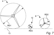
- Fig. 7 illustrates the different rotor diameters RD1, RD2, RD3 of the first type rotor 4, the second type rotor 8 and the third type rotor 12, respectively. Apart from that, Fig. 7 also illustrates (as do Figs. 4 and 6 ) how, for preferred embodiments of the invention, especially ones in which the energy production site 5, 9 is an offshore site, the first type wind turbines 2, the second type wind turbines 6 and, where applicable, the third type wind turbines 10 are arranged with a common lower rotor limit 13.
- the average heights of the lowest points of the first type rotors 4, the second type rotors 8 and, where applicable, the third type rotors 12 are all aligned at, or at least within limited predefined distance from, this common lower rotor limit 13, these average heights being measured over time.
Landscapes
- Engineering & Computer Science (AREA)
- Life Sciences & Earth Sciences (AREA)
- Sustainable Development (AREA)
- Sustainable Energy (AREA)
- Chemical & Material Sciences (AREA)
- Combustion & Propulsion (AREA)
- Mechanical Engineering (AREA)
- General Engineering & Computer Science (AREA)
- Power Engineering (AREA)
- Wind Motors (AREA)
Applications Claiming Priority (1)
| Application Number | Priority Date | Filing Date | Title |
|---|---|---|---|
| DKPA202370290A DK202370290A1 (en) | 2023-06-14 | 2023-06-14 | An energy production site with different size wind turbines |
Publications (1)
| Publication Number | Publication Date |
|---|---|
| EP4477875A1 true EP4477875A1 (de) | 2024-12-18 |
Family
ID=93561796
Family Applications (1)
| Application Number | Title | Priority Date | Filing Date |
|---|---|---|---|
| EP24181601.6A Withdrawn EP4477875A1 (de) | 2023-06-14 | 2024-06-12 | Energieerzeugungsanlage mit windturbinen verschiedener grösse |
Country Status (2)
| Country | Link |
|---|---|
| EP (1) | EP4477875A1 (de) |
| DK (1) | DK202370290A1 (de) |
Citations (4)
| Publication number | Priority date | Publication date | Assignee | Title |
|---|---|---|---|---|
| US20070138797A1 (en) * | 2005-10-20 | 2007-06-21 | Michael Reidy | Wind energy harnessing apparatuses, systems, methods, and improvements |
| US20100115951A1 (en) * | 2007-04-27 | 2010-05-13 | Lm Glasfiber A/S | Design of a group of wind power plants |
| WO2011120521A1 (en) * | 2010-03-31 | 2011-10-06 | Per Uggen | Foating foundation equipped with two primary wind turbines |
| US20210071641A1 (en) * | 2017-12-14 | 2021-03-11 | Vestas Wind Systems A/S | Wind energy farm with cable stayed wind turbines |
Family Cites Families (7)
| Publication number | Priority date | Publication date | Assignee | Title |
|---|---|---|---|---|
| US6749399B2 (en) * | 2002-03-07 | 2004-06-15 | Ocean Wind Energy Systems | Vertical array wind turbine |
| CN102959131B (zh) * | 2010-04-28 | 2015-08-26 | 英格蒂姆能源科技公司 | 用于控制基于可再生能源的发电站的功率输出的制氢系统及其控制方法 |
| US8474219B2 (en) * | 2011-07-13 | 2013-07-02 | Ultimate Strength Cable, LLC | Stay cable for structures |
| CN108317038A (zh) * | 2018-01-15 | 2018-07-24 | 西北工业大学 | 一种海上风电抗台风主被动减载控制系统 |
| CN112523969B (zh) * | 2020-11-30 | 2023-02-28 | 中国电建集团华东勘测设计研究院有限公司 | 一种桁架拉索型漂浮式海上风电机组结构 |
| CN115539312A (zh) * | 2022-09-27 | 2022-12-30 | 中国华能集团有限公司南方分公司 | 一种带斜拉索的漂浮式海上风电机组 |
| CN115467356A (zh) * | 2022-10-26 | 2022-12-13 | 袁小荣 | 一种顺应式海上风力发电机基础结构系统 |
-
2023
- 2023-06-14 DK DKPA202370290A patent/DK202370290A1/en not_active Application Discontinuation
-
2024
- 2024-06-12 EP EP24181601.6A patent/EP4477875A1/de not_active Withdrawn
Patent Citations (4)
| Publication number | Priority date | Publication date | Assignee | Title |
|---|---|---|---|---|
| US20070138797A1 (en) * | 2005-10-20 | 2007-06-21 | Michael Reidy | Wind energy harnessing apparatuses, systems, methods, and improvements |
| US20100115951A1 (en) * | 2007-04-27 | 2010-05-13 | Lm Glasfiber A/S | Design of a group of wind power plants |
| WO2011120521A1 (en) * | 2010-03-31 | 2011-10-06 | Per Uggen | Foating foundation equipped with two primary wind turbines |
| US20210071641A1 (en) * | 2017-12-14 | 2021-03-11 | Vestas Wind Systems A/S | Wind energy farm with cable stayed wind turbines |
Also Published As
| Publication number | Publication date |
|---|---|
| DK202370290A1 (en) | 2025-01-15 |
| DK202370290A8 (en) | 2025-10-27 |
Similar Documents
| Publication | Publication Date | Title |
|---|---|---|
| Wagner | Introduction to wind energy systems | |
| EP2235367B1 (de) | Windpark | |
| Bhutto et al. | Greener energy: Issues and challenges for Pakistan—wind power prospective | |
| US10344741B2 (en) | Hydro-pneumatic energy storage system | |
| US7902687B2 (en) | Submersible turbine-generator unit for ocean and tidal currents | |
| US20100135768A1 (en) | Column structure with protected turbine | |
| AU2018382243B2 (en) | A wind energy farm with cable stayed wind turbines | |
| CN105569928A (zh) | 单点系泊式深海浮式风机 | |
| Mohammad et al. | A review of the state of the art of generators and power electronics for wind energy conversion systems | |
| Wagner | Introduction to wind energy systems | |
| WO2010098814A1 (en) | Improved wind energy device | |
| EP4477875A1 (de) | Energieerzeugungsanlage mit windturbinen verschiedener grösse | |
| Milborrow | Wind energy technology—the state of the art | |
| Yao et al. | Wind energy resources: theory, design and applications | |
| Musial | Offshore wind energy facility characteristics | |
| US20130056990A1 (en) | Modular Wind Turbine | |
| EP4477872A1 (de) | Windpark mit hohem leistungsfaktor | |
| Eltamaly | Introduction to Wind Energy System | |
| Samantaray et al. | A study of wind energy potential in India | |
| Carter | Renewable Energy Technologies: Mechanical Design and System Integration | |
| Musgrove | Wind energy | |
| Mahmud et al. | Wind power technology schemes as renewable energy in Bangladesh | |
| Gasch et al. | Offshore wind farms | |
| WO2009126533A2 (en) | Building-based wind cylinder installation | |
| Rekioua | Wind Turbine Applications Overview |
Legal Events
| Date | Code | Title | Description |
|---|---|---|---|
| PUAI | Public reference made under article 153(3) epc to a published international application that has entered the european phase |
Free format text: ORIGINAL CODE: 0009012 |
|
| STAA | Information on the status of an ep patent application or granted ep patent |
Free format text: STATUS: THE APPLICATION HAS BEEN PUBLISHED |
|
| AK | Designated contracting states |
Kind code of ref document: A1 Designated state(s): AL AT BE BG CH CY CZ DE DK EE ES FI FR GB GR HR HU IE IS IT LI LT LU LV MC ME MK MT NL NO PL PT RO RS SE SI SK SM TR |
|
| STAA | Information on the status of an ep patent application or granted ep patent |
Free format text: STATUS: THE APPLICATION IS DEEMED TO BE WITHDRAWN |
|
| 18D | Application deemed to be withdrawn |
Effective date: 20250619 |