EP4477876A1 - Verfahren zur installation einer windenergieanlage und windenergieanlage - Google Patents
Verfahren zur installation einer windenergieanlage und windenergieanlage Download PDFInfo
- Publication number
- EP4477876A1 EP4477876A1 EP23178982.7A EP23178982A EP4477876A1 EP 4477876 A1 EP4477876 A1 EP 4477876A1 EP 23178982 A EP23178982 A EP 23178982A EP 4477876 A1 EP4477876 A1 EP 4477876A1
- Authority
- EP
- European Patent Office
- Prior art keywords
- transition
- connector
- functional
- wind turbine
- platform
- Prior art date
- Legal status (The legal status is an assumption and is not a legal conclusion. Google has not performed a legal analysis and makes no representation as to the accuracy of the status listed.)
- Pending
Links
Images




Classifications
-
- F—MECHANICAL ENGINEERING; LIGHTING; HEATING; WEAPONS; BLASTING
- F03—MACHINES OR ENGINES FOR LIQUIDS; WIND, SPRING, OR WEIGHT MOTORS; PRODUCING MECHANICAL POWER OR A REACTIVE PROPULSIVE THRUST, NOT OTHERWISE PROVIDED FOR
- F03D—WIND MOTORS
- F03D13/00—Assembly, mounting or commissioning of wind motors; Arrangements specially adapted for transporting wind motor components
- F03D13/10—Assembly of wind motors; Arrangements for erecting wind motors
- F03D13/112—Assembly of wind motors; Arrangements for erecting wind motors of towers; of masts
-
- F—MECHANICAL ENGINEERING; LIGHTING; HEATING; WEAPONS; BLASTING
- F03—MACHINES OR ENGINES FOR LIQUIDS; WIND, SPRING, OR WEIGHT MOTORS; PRODUCING MECHANICAL POWER OR A REACTIVE PROPULSIVE THRUST, NOT OTHERWISE PROVIDED FOR
- F03D—WIND MOTORS
- F03D1/00—Wind motors with rotation axis substantially parallel to the air flow entering the rotor
- F03D1/06—Rotors
- F03D1/065—Rotors characterised by their construction elements
- F03D1/0675—Rotors characterised by their construction elements of the blades
- F03D1/0677—Longitudinally segmented blades; Connectors therefor
-
- F—MECHANICAL ENGINEERING; LIGHTING; HEATING; WEAPONS; BLASTING
- F03—MACHINES OR ENGINES FOR LIQUIDS; WIND, SPRING, OR WEIGHT MOTORS; PRODUCING MECHANICAL POWER OR A REACTIVE PROPULSIVE THRUST, NOT OTHERWISE PROVIDED FOR
- F03D—WIND MOTORS
- F03D13/00—Assembly, mounting or commissioning of wind motors; Arrangements specially adapted for transporting wind motor components
- F03D13/10—Assembly of wind motors; Arrangements for erecting wind motors
- F03D13/126—Offshore
-
- F—MECHANICAL ENGINEERING; LIGHTING; HEATING; WEAPONS; BLASTING
- F03—MACHINES OR ENGINES FOR LIQUIDS; WIND, SPRING, OR WEIGHT MOTORS; PRODUCING MECHANICAL POWER OR A REACTIVE PROPULSIVE THRUST, NOT OTHERWISE PROVIDED FOR
- F03D—WIND MOTORS
- F03D13/00—Assembly, mounting or commissioning of wind motors; Arrangements specially adapted for transporting wind motor components
- F03D13/20—Arrangements for mounting or supporting wind motors; Masts or towers for wind motors
- F03D13/25—Arrangements for mounting or supporting wind motors; Masts or towers for wind motors specially adapted for offshore installation
-
- F—MECHANICAL ENGINEERING; LIGHTING; HEATING; WEAPONS; BLASTING
- F05—INDEXING SCHEMES RELATING TO ENGINES OR PUMPS IN VARIOUS SUBCLASSES OF CLASSES F01-F04
- F05B—INDEXING SCHEME RELATING TO WIND, SPRING, WEIGHT, INERTIA OR LIKE MOTORS, TO MACHINES OR ENGINES FOR LIQUIDS COVERED BY SUBCLASSES F03B, F03D AND F03G
- F05B2240/00—Components
- F05B2240/90—Mounting on supporting structures or systems
- F05B2240/95—Mounting on supporting structures or systems offshore
-
- Y—GENERAL TAGGING OF NEW TECHNOLOGICAL DEVELOPMENTS; GENERAL TAGGING OF CROSS-SECTIONAL TECHNOLOGIES SPANNING OVER SEVERAL SECTIONS OF THE IPC; TECHNICAL SUBJECTS COVERED BY FORMER USPC CROSS-REFERENCE ART COLLECTIONS [XRACs] AND DIGESTS
- Y02—TECHNOLOGIES OR APPLICATIONS FOR MITIGATION OR ADAPTATION AGAINST CLIMATE CHANGE
- Y02E—REDUCTION OF GREENHOUSE GAS [GHG] EMISSIONS, RELATED TO ENERGY GENERATION, TRANSMISSION OR DISTRIBUTION
- Y02E10/00—Energy generation through renewable energy sources
- Y02E10/70—Wind energy
- Y02E10/72—Wind turbines with rotation axis in wind direction
Definitions
- the rotating of the functional platform relative to the transition unit is stopped in the first end position by a bumper device of the functional platform and/or the transition unit.
- the rotating action is limited by the bumper device.
- the bumper device can be integrated into the second functional connector and/or the second transition connector.
- the bumper device has a second function, namely a vertical guiding rail.
- the bumper device can comprise a dampening device to avoid rough mechanical impact between the second functional connector and the transition unit at adverse weather conditions. This has the advantage that in a simple and inexpensive way, the secure installation of the functional platform at the transition unit is further improved.
- the method can comprise that the arranging of the functional platform at the transition unit is performed by simultaneously aligning the first functional connector with the first transition connector and the second functional connector with the second transition connector by horizontally moving the functional platform relative to the transition unit to a first end position, wherein in the first end position, the first functional connector is arranged vertically above the first transition connector or at least a part of the first transition connector and the second functional connector is arranged vertically above the second transition connector or at least a part of the second transition connector.
- the first functional connector in an initial position of the functional platform, the first functional connector is horizontally and vertically spaced apart from the first transition connector and the second functional connector is horizontally and vertically spaced apart from the second transition connector.
- the horizontal movement of the functional platform is preferably such that the horizontal component is eliminated in the first end position. This has the advantage that in a simple and inexpensive way, the secure installation of the functional platform at the transition unit is further improved.
- the functional platform in the first end position, is lowered until the first functional connector engages with the first transition connector in the final end position and/or the second functional connector engages with the second transition connector in the final end position.
- getting into an engagement is considered as a further limiting of a degree of freedom.
- this is realized by mutual form fit, such as a snap in mechanism, a hook and pin mechanism or the like.
- the limiting of the degree of freedom is preferably such that only a vertical upward movement of the functional platform relatively to the transition unit is allowed.
- the functional platform is held in place by gravity. This has the advantage that in a simple and inexpensive way, the secure installation of the functional platform at the transition unit is further improved.
- the arranging of the functional platform at the transition unit is performed such that a rod-shaped third functional connector of the functional platform engages with a third transition connector of the transition piece, wherein the third transition connector is arranged at a lower height than the first transition connector and/or the second transition connector.
- the third functional connector and the third transition connector By the third functional connector and the third transition connector, a rotational moment of the functional platform about the first functional connector and the second functional connector can be reduced.
- a plurality of third functional connectors and third transition connectors is provided to distribute the load of the functional platform, preferably equally. It is preferred that the third transition connector has a u-shaped, v-shaped or similar cross section for receiving and holding the third functional connector in place. This has the advantage that in a simple and inexpensive way, the stability of the functional platform at the transition unit is improved.
- the functional platform is provided with at least one electrochemical production unit installed.
- a plurality of electrochemical production units is installed on top of the functional platform.
- the object is achieved by a wind turbine system with a wind turbine for converting wind energy into electrical energy and a functional platform for providing a technical function based on the electrical energy provided by the wind turbine.
- the wind turbine system is installed by a method according to the invention.
- the wind turbine system according to the invention has all the advantages that have already been described for a method for installing a wind turbine system according to the first aspect of the invention. Accordingly, the wind turbine system according to the invention has the advantage over conventional wind turbine systems that in a simple and inexpensive way, a functional platform is arranged at an already erected wind turbine. Thus, the wind turbine can produce electric energy before the functional platform is installed, already. This is also advantageous, when the availability of material for the functional platform and components for being placed on top of the functional platform, such as chemical production units or the like, are subject to delivery problems or delivery delay. The assembly of the wind turbine can continue, even without the functional platform.
- the complete functional platform, especially together with the further components installed on top of the functional platform can be easily tested prior installation, by these means, defects can be identified at an early stage. Beyond that, replacement of the complete functional platform, especially together with the further components installed on top of the functional platform, is easier. Thus, an obsolete or defect functional platform can be exchanged within short time. Even for maintenance of the functional platform, especially together with the further components installed on top of the functional platform, the functional platform can be exchanged easily.
- the demounted functional platform can be serviced at landsite then, in a safe environment.
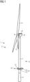
- a wind turbine system 1 according to a preferred embodiment of the invention is shown in a schematic side view.
- the wind turbine system 1 comprises a wind turbine 2 and a functional platform 13.
- the wind turbine 2 comprises a wind turbine tower 3 with a base section 4 at a lower end, a transition piece 5 installed on top of the base section 4 and an upper tower section 7, installed on top of the transition piece 5.
- the upper tower section 7 can comprise a plurality of not shown section elements, stacked up to constitute the upper tower section 7.
- a working platform 6 is arranged.
- the transition piece 5 and the working platform 6 form a transition unit 12.
- the functional platform 13 is arranged at the transition unit 12 in a way that a platform of the functional platform 13 is on the same height level than the working platform 6.
- a nacelle 8 with a rotor 9 and a generator 10 is mounted on top of the wind turbine tower 3.
- the generator 10 is arranged within an interior of the nacelle 8.
- the rotor 9 is partly arranged inside the nacelle 8, wherein a hub of the rotor is arranged outside of the nacelle 8.
- three wind turbine blades 11 are installed at the hub of the rotor 9.
- wind energy can be transformed into rotational energy and the rotational energy can be transformed into electrical energy by the wind turbine 2.
- the electrical energy can be used by the electrochemical production units 21 for converting chemicals.
- a functional platform 13 according to a preferred first embodiment of the invention is shown in a schematic perspective view.
- the functional platform 13 has a c-shaped design for arranging around the wind turbine tower 3 at the transition piece 5 in a horizontal, linear movement.
- Fig. 7 shows the functional platform 13 of fig. 6 in another schematic perspective view and attached to a crane.
- a plurality of rod-shaped third functional connector 19, which are attached to a bottom of the functional platform 13 are visible.
- the third functional connectors 19 are provided for stabilizing the functional platform 13 against the transition piece 5.
- the functional platform 13 can be installed at the wind turbine 2 according to the method of the invention.
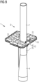
- a wind turbine system 1 according to the preferred first embodiment of the invention is shown in a schematic perspective view.
- the functional platform 13 of fig. 6 is arranged at the transition unit 12 of the wind turbine 2.
- the functional platform 13 is horizontally aligned with the working platform 6 and, preferably, connected to the working platform 6 to constitute a common platform.
- the nacelle 8 with rotor 9 and wind turbine blades 11 is not shown.
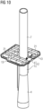
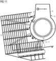
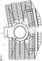
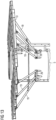
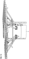
- Fig. 9 to fig. 12 show a wind turbine system 1 according to a preferred second embodiment of the invention.
- a half-sized functional platform 13 is arranged at one side of the transition unit 12.
- another half-sized functional platform 13 is arranged at the other side of the transition unit 12.
- a nacelle 8 with rotor 9 and wind turbine blades 11 is not shown.
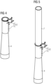
- a first functional connector 14 of the functional platform 13 is engaged with a first transition connector 15 of the transition unit 5, thus forming a hinge-like connection.
- the first transition connector 15 is attached to the working platform 6.
- the functional platform 13 is rotated clock-wise about a vertical connection axis V, which is defined by the connection of the first functional connector 14 with the first transition connector 15.
- the rotation ends when a second functional connector 16 of the functional platform 13 engages with a second transition connector 17 of the transition unit 12.
- the second transition connector 17 is attached to the working platform 6. More functional connectors and transition connectors can be provided.
- Fig. 13 and fig. 14 show two different embodiments of third functional connectors 19 of the functional platform 13 in engagement with third transition connectors 20 of the transition piece 5.
- the third functional connectors 19 comprise bolts, which are inserted into brackets of the third transition connectors 20.
- the third functional connectors 19 are hinged to brackets of the third transition connectors 20.
- the alignment of the second functional connector 16 with the second transition connector 17 is shown in the final end position F. From the first end position E to the final end position F, the functional platform 13 has been lowered in a vertical direction. By these means, a form fit part of the second functional connector 16 is engaged with a form fit part of the second transition connector 17. Thus, a horizontal movement of the functional platform 13 is prevented.
Landscapes
- Engineering & Computer Science (AREA)
- Life Sciences & Earth Sciences (AREA)
- Sustainable Development (AREA)
- Sustainable Energy (AREA)
- Chemical & Material Sciences (AREA)
- Combustion & Propulsion (AREA)
- Mechanical Engineering (AREA)
- General Engineering & Computer Science (AREA)
- Wind Motors (AREA)
Priority Applications (1)
| Application Number | Priority Date | Filing Date | Title |
|---|---|---|---|
| EP23178982.7A EP4477876A1 (de) | 2023-06-13 | 2023-06-13 | Verfahren zur installation einer windenergieanlage und windenergieanlage |
Applications Claiming Priority (1)
| Application Number | Priority Date | Filing Date | Title |
|---|---|---|---|
| EP23178982.7A EP4477876A1 (de) | 2023-06-13 | 2023-06-13 | Verfahren zur installation einer windenergieanlage und windenergieanlage |
Publications (1)
| Publication Number | Publication Date |
|---|---|
| EP4477876A1 true EP4477876A1 (de) | 2024-12-18 |
Family
ID=86764430
Family Applications (1)
| Application Number | Title | Priority Date | Filing Date |
|---|---|---|---|
| EP23178982.7A Pending EP4477876A1 (de) | 2023-06-13 | 2023-06-13 | Verfahren zur installation einer windenergieanlage und windenergieanlage |
Country Status (1)
| Country | Link |
|---|---|
| EP (1) | EP4477876A1 (de) |
Citations (4)
| Publication number | Priority date | Publication date | Assignee | Title |
|---|---|---|---|---|
| EP2581336A1 (de) * | 2010-06-09 | 2013-04-17 | Sinovel Wind Group Co., Ltd | Multifunktionsplattform einer windkraftanlage und schaufelzerlegungsverfahren |
| EP2863053A1 (de) * | 2013-10-17 | 2015-04-22 | Siemens Aktiengesellschaft | Einteilige, elektrische Anordnung für den Anschluss einer Offshore-Windturbine an ein Untersee-Elektrokabel sowie Montageverfahren |
| EP4123171A1 (de) * | 2021-07-19 | 2023-01-25 | Siemens Gamesa Renewable Energy A/S | Offshore-windturbine mit einer flüssigkeitsversorgungsanordnung mit einem schlauch und einer schlauchhaspel |
| EP4184006A1 (de) * | 2021-11-19 | 2023-05-24 | Siemens Gamesa Renewable Energy A/S | Verfahren zur anordnung von mindestens einer komponente während der montage einer windturbine |
-
2023
- 2023-06-13 EP EP23178982.7A patent/EP4477876A1/de active Pending
Patent Citations (4)
| Publication number | Priority date | Publication date | Assignee | Title |
|---|---|---|---|---|
| EP2581336A1 (de) * | 2010-06-09 | 2013-04-17 | Sinovel Wind Group Co., Ltd | Multifunktionsplattform einer windkraftanlage und schaufelzerlegungsverfahren |
| EP2863053A1 (de) * | 2013-10-17 | 2015-04-22 | Siemens Aktiengesellschaft | Einteilige, elektrische Anordnung für den Anschluss einer Offshore-Windturbine an ein Untersee-Elektrokabel sowie Montageverfahren |
| EP4123171A1 (de) * | 2021-07-19 | 2023-01-25 | Siemens Gamesa Renewable Energy A/S | Offshore-windturbine mit einer flüssigkeitsversorgungsanordnung mit einem schlauch und einer schlauchhaspel |
| EP4184006A1 (de) * | 2021-11-19 | 2023-05-24 | Siemens Gamesa Renewable Energy A/S | Verfahren zur anordnung von mindestens einer komponente während der montage einer windturbine |
Similar Documents
| Publication | Publication Date | Title |
|---|---|---|
| US9476403B2 (en) | Wind turbine blade lowering apparatus | |
| CA3080664C (en) | Flange frame and assembly set for pre-assembling and/or transporting and/or assembling a tower segment for a wind turbine, and methods | |
| US9869293B2 (en) | Wind turbine tower guide system, and a method for installing an installation unit | |
| US9982658B2 (en) | Offshore wind turbine, method for constructing offshore wind turbine, and offshore wind power generator | |
| AU2003211860B2 (en) | Wind energy turbine | |
| US7874805B2 (en) | Hub for a wind turbine | |
| JP5557858B2 (ja) | 風力発電設備 | |
| EP3825549B1 (de) | Turm für eine windturbine und windturbine | |
| CN110177940B (zh) | 用于风力涡轮机的电气单元 | |
| US8528735B2 (en) | Transport frame for nacelle/rotor hub unit of a wind turbine, method of transporting and mounting a nacelle/rotor hub unit | |
| KR102008156B1 (ko) | 풍력 터빈 타워 이렉팅 시스템 | |
| EP2108816A2 (de) | Verfahren und System zur Montage von Komponenten in einem Turm einer Windenergieturbine | |
| EP3891390B1 (de) | Verfahren zur herstellung einer windturbine und turm einer windturbine | |
| EP4477876A1 (de) | Verfahren zur installation einer windenergieanlage und windenergieanlage | |
| US12241449B2 (en) | Method for manufacturing a wind turbine and wind turbine | |
| EP4481192A1 (de) | Plattformsystem und windturbine | |
| EP4450806A1 (de) | Elektrochemisches produktionssystem, plattformsystem und windturbine | |
| US11754049B2 (en) | Platform for a wind turbine, wind turbine with the platform and method for assembling a wind turbine | |
| WO2023090995A1 (en) | An improved offshore wind turbine |
Legal Events
| Date | Code | Title | Description |
|---|---|---|---|
| PUAI | Public reference made under article 153(3) epc to a published international application that has entered the european phase |
Free format text: ORIGINAL CODE: 0009012 |
|
| STAA | Information on the status of an ep patent application or granted ep patent |
Free format text: STATUS: THE APPLICATION HAS BEEN PUBLISHED |
|
| AK | Designated contracting states |
Kind code of ref document: A1 Designated state(s): AL AT BE BG CH CY CZ DE DK EE ES FI FR GB GR HR HU IE IS IT LI LT LU LV MC ME MK MT NL NO PL PT RO RS SE SI SK SM TR |
|
| STAA | Information on the status of an ep patent application or granted ep patent |
Free format text: STATUS: REQUEST FOR EXAMINATION WAS MADE |
|
| GRAP | Despatch of communication of intention to grant a patent |
Free format text: ORIGINAL CODE: EPIDOSNIGR1 |
|
| STAA | Information on the status of an ep patent application or granted ep patent |
Free format text: STATUS: GRANT OF PATENT IS INTENDED |
|
| 17P | Request for examination filed |
Effective date: 20250618 |
|
| RIC1 | Information provided on ipc code assigned before grant |
Ipc: F03D 13/10 20160101AFI20250704BHEP Ipc: F03D 13/25 20160101ALI20250704BHEP |
|
| INTG | Intention to grant announced |
Effective date: 20250722 |
|
| STAA | Information on the status of an ep patent application or granted ep patent |
Free format text: STATUS: THE APPLICATION IS DEEMED TO BE WITHDRAWN |