EP4477925A1 - Disque de rupture angulaire, en particulier rectangulaire - Google Patents
Disque de rupture angulaire, en particulier rectangulaire Download PDFInfo
- Publication number
- EP4477925A1 EP4477925A1 EP23178734.2A EP23178734A EP4477925A1 EP 4477925 A1 EP4477925 A1 EP 4477925A1 EP 23178734 A EP23178734 A EP 23178734A EP 4477925 A1 EP4477925 A1 EP 4477925A1
- Authority
- EP
- European Patent Office
- Prior art keywords
- shoulder
- rupture disc
- sheet metal
- rupture disk
- rupture
- Prior art date
- Legal status (The legal status is an assumption and is not a legal conclusion. Google has not performed a legal analysis and makes no representation as to the accuracy of the status listed.)
- Pending
Links
Images




Classifications
-
- F—MECHANICAL ENGINEERING; LIGHTING; HEATING; WEAPONS; BLASTING
- F16—ENGINEERING ELEMENTS AND UNITS; GENERAL MEASURES FOR PRODUCING AND MAINTAINING EFFECTIVE FUNCTIONING OF MACHINES OR INSTALLATIONS; THERMAL INSULATION IN GENERAL
- F16K—VALVES; TAPS; COCKS; ACTUATING-FLOATS; DEVICES FOR VENTING OR AERATING
- F16K17/00—Safety valves; Equalising valves, e.g. pressure relief valves
- F16K17/02—Safety valves; Equalising valves, e.g. pressure relief valves opening on surplus pressure on one side; closing on insufficient pressure on one side
- F16K17/14—Safety valves; Equalising valves, e.g. pressure relief valves opening on surplus pressure on one side; closing on insufficient pressure on one side with fracturing member
- F16K17/16—Safety valves; Equalising valves, e.g. pressure relief valves opening on surplus pressure on one side; closing on insufficient pressure on one side with fracturing member with fracturing diaphragm ; Rupture discs
-
- B—PERFORMING OPERATIONS; TRANSPORTING
- B65—CONVEYING; PACKING; STORING; HANDLING THIN OR FILAMENTARY MATERIAL
- B65D—CONTAINERS FOR STORAGE OR TRANSPORT OF ARTICLES OR MATERIALS, e.g. BAGS, BARRELS, BOTTLES, BOXES, CANS, CARTONS, CRATES, DRUMS, JARS, TANKS, HOPPERS, FORWARDING CONTAINERS; ACCESSORIES, CLOSURES, OR FITTINGS THEREFOR; PACKAGING ELEMENTS; PACKAGES
- B65D90/00—Component parts, details or accessories for large containers
- B65D90/22—Safety features
- B65D90/32—Arrangements for preventing, or minimising the effect of, excessive or insufficient pressure
- B65D90/36—Weakened parts
Definitions
- the present invention relates to an angular, in particular rectangular, rupture disk which is made of a sheet metal, with an edge region with which the rupture disk can be attached to an opening of a container or a line, and with a central region with which the opening can be closed off up to a bursting pressure, and with predetermined breaking lines along which the rupture disk tears open when the bursting pressure is reached, so that the central region opens completely or in part.
- the EGV is used, for example, in systems with silos, spray dryers, elevators, trough chain conveyors, sieves with slight vibration, containers with mechanical filling or cyclones, especially in pressureless processes and processes with slight negative or positive pressure.
- the bursting disc can be used to prevent a pressure increase in containers or lines above the bursting pressure. If the pressure increases above the bursting pressure, the EGV opens at the defined predetermined breaking lines and thus releases the pressure from the container or line into the environment.
- the EGV in its current design is made up of several parts. It comprises a cut and formed sheet metal with two circumferential beads and four so-called clip-on sheets, one of which is clipped onto each side of the sheet metal.
- the sheet metal covers the middle area and part of the edge area of the bursting disc. Other parts of the edge area are formed by the clip-on strips.
- the sheet metal contains the predetermined breaking lines, which tear open when the bursting pressure is reached.
- the clip-on sheets are U-shaped strips in cross-section with a very narrow web that is approximately as wide as the sheet metal is thick, and with Legs of different lengths that grip the edge of the sheet.
- the sheet metal is produced in several work steps.
- the clip-on strips are produced in several work steps.
- the clip-on strips are then plugged onto the sheet metal.
- these clip-on strips are then secured against coming loose from the sheet metal during transport or when the rupture disc is being installed and possibly getting lost or damaged. Clamps are currently used for this purpose, which also have to be manufactured, installed and then dismantled again.
- the invention is therefore based on the object of designing a square rupture disc in such a way that it can be manufactured more easily.
- the rupture disk has a fold in the edge region, which has a first folded part of the sheet and a second part of the sheet, to which the folded part is parallel or predominantly parallel.
- a fold is also referred to by experts as a fold.
- a rupture disk according to the invention In a rupture disk according to the invention, the mounting strips are thus eliminated and the edge area of the rupture disk is formed by the sheet metal, the edge of which is folded over.
- the forming of the sheet metal to form the rupture disk according to the invention is therefore more complex than the production of the sheet metal of the EGV alone.
- the production of the rupture disc is less complex overall.
- the rupture disc can thus be formed from sheet metal in one workstation in particular and no parts, such as push-on strips, have to be produced and supplied at another workstation or supplied from a stock. In the case of a rupture disc according to the invention, no transport lock is required to secure push-on strips.
- holes can be provided in the envelope which are suitable for screws for screwing the rupture disc to an edge of the opening.
- a rupture disk according to the invention it is possible for a rupture disk according to the invention to have a first step in the first or second part. If the step is provided in the first or second part, a distance can be provided between the first part and the second part starting from the edge of the rupture disk up to the first step, while then from the first step onwards the first part and the second part can lie against one another.
- a rupture disk according to the invention can have a second shoulder in the middle area at a distance from the cover.
- the second shoulder can go in the same direction as the first shoulder. However, it is also possible for the second shoulder to go in the opposite direction to the first shoulder.
- less forming energy is used to produce the shoulders. This has the advantage that the sheet is less likely to be undesirably deformed when producing these shoulders, in contrast to a sheet of the EGV into which the beads are introduced.
- the rupture disks may no longer be flat when not assembled, but may develop a so-called frog shape, which means that corners of the rupture disk or sheet are raised out of the plane that the sheet should form. Although this has no effect on the function of the rupture disk, it does at least make the assembly of the known rupture disk slightly more difficult.
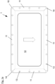
- the bursting disc 1 is made of a sheet metal that is specially cut to size.
- the sheet metal has been notched at the corners.
- the sheet metal is secured by means of a Setting tool with a first shoulder 15 and a second shoulder 16.
- the first shoulder 15 is made further out in the sheet metal and the second shoulder 16 further in.
- pairs of holes 13 have been made in the sheet metal, the holes 13 being the same size.
- the two holes 13 of a pair are equally spaced on a line perpendicular to a straight line along which the sheet metal is folded over by 180° to create a fold, in order to create an edge region 11 of the sheet metal. After folding, the holes 13 of a pair lie one above the other and are aligned.
- Additional holes 14 are provided in the sheet metal at the corners. All of these holes 13, 14 are used to attach the rupture disk 1, which can be screwed to a container or pipe using screws that can be passed through these holes 13, 14.
- a central region 12 of the rupture disk 1 is formed, in which the second shoulder 16 is provided.
- the first shoulder is located in the edge region 11.
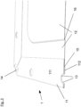
- the fold forms two parts 111, 112 of the sheet in the edge region 11, namely a first folded part 111 and a second part 112 parallel to the folded part 111.
- the first step 15 is formed in the second part 112. This creates an area in which the first part 111 and the second part 112 are spaced apart from one another, and an area further inside in which the first part 111 and the second part 112 lie against one another. In this area, in which the first part 111 and the second part 112 lie against one another, predetermined breaking lines (not shown) are provided, along which the rupture disk 1 tears and opens when a bursting pressure is reached.
- the first part 111 and the second part 112 may be located in areas between the cover and the paragraph 15 lie against each other.
- these areas can be curved towards each other, in particular where the holes 13 are provided, but also in an area adjacent to the fold.
- This curvature can be created during the manufacture of the rupture disk, for example during folding.
- Both the second rupture disc after the Fig. 4a as well as the rupture disc after the Fig. 4b which, apart from the differences shown in the rupture disc according to the Figures 1 to 4
- the first part 111 and the second part 112 are adjacent to each other.
- the second rupture disc is Fig. 4a and also with the third rupture disc after Fig. 4b
- a third shoulder 17 is formed by means of a setting tool, which nestles against the first shoulder 15.
- the first shoulder 15 and the third shoulder 17 can be produced in one operation if the cover has been produced beforehand.
- a fourth shoulder 18 is provided in the first region, which is directed opposite to the first shoulder 15. This forms a circumferential recess in the second part 112 of the edge region 11.
- a seal 2 can be arranged on the first shoulder 15 adjacent to the second part 112 of the edge region 11, which seal 2 rests on the edge of an opening to be closed when the rupture disk 1 is mounted and seals a gap between the rupture disk 1 and the edge of the opening.
- the first shoulder 15 prevents that this seal 2 is compressed so much during assembly that it is damaged and then possibly no longer fulfills its purpose of sealing.
- the seal 2 can be a sealing strip that is glued to the second part 112. Alternatively, it can also be a foamed seal 2 that is molded on.
- the location in which the seal 2 can be arranged is limited on both sides by the circumferential recess.
Landscapes
- Engineering & Computer Science (AREA)
- General Engineering & Computer Science (AREA)
- Mechanical Engineering (AREA)
- Safety Valves (AREA)
Priority Applications (4)
| Application Number | Priority Date | Filing Date | Title |
|---|---|---|---|
| EP25190982.6A EP4663988A1 (fr) | 2023-06-12 | 2023-06-12 | Disque de rupture angulaire, en particulier rectangulaire |
| EP23178734.2A EP4477925A1 (fr) | 2023-06-12 | 2023-06-12 | Disque de rupture angulaire, en particulier rectangulaire |
| US18/740,041 US20240409308A1 (en) | 2023-06-12 | 2024-06-11 | Rectangular rupture disk |
| CN202410749136.6A CN119123127A (zh) | 2023-06-12 | 2024-06-12 | 多角的、特别是矩形的爆破片 |
Applications Claiming Priority (1)
| Application Number | Priority Date | Filing Date | Title |
|---|---|---|---|
| EP23178734.2A EP4477925A1 (fr) | 2023-06-12 | 2023-06-12 | Disque de rupture angulaire, en particulier rectangulaire |
Related Child Applications (1)
| Application Number | Title | Priority Date | Filing Date |
|---|---|---|---|
| EP25190982.6A Division EP4663988A1 (fr) | 2023-06-12 | 2023-06-12 | Disque de rupture angulaire, en particulier rectangulaire |
Publications (1)
| Publication Number | Publication Date |
|---|---|
| EP4477925A1 true EP4477925A1 (fr) | 2024-12-18 |
Family
ID=86760558
Family Applications (2)
| Application Number | Title | Priority Date | Filing Date |
|---|---|---|---|
| EP25190982.6A Pending EP4663988A1 (fr) | 2023-06-12 | 2023-06-12 | Disque de rupture angulaire, en particulier rectangulaire |
| EP23178734.2A Pending EP4477925A1 (fr) | 2023-06-12 | 2023-06-12 | Disque de rupture angulaire, en particulier rectangulaire |
Family Applications Before (1)
| Application Number | Title | Priority Date | Filing Date |
|---|---|---|---|
| EP25190982.6A Pending EP4663988A1 (fr) | 2023-06-12 | 2023-06-12 | Disque de rupture angulaire, en particulier rectangulaire |
Country Status (3)
| Country | Link |
|---|---|
| US (1) | US20240409308A1 (fr) |
| EP (2) | EP4663988A1 (fr) |
| CN (1) | CN119123127A (fr) |
Citations (2)
| Publication number | Priority date | Publication date | Assignee | Title |
|---|---|---|---|---|
| FR2870833B1 (fr) * | 2004-05-26 | 2006-07-28 | D T I Soc Par Actions Simplifi | Panneau de protection d'une enceinte et enceinte ainsi equipee |
| FR2943043A1 (fr) * | 2009-03-11 | 2010-09-17 | Societe De Tolerie Industrielle Francaise | Panneau de protection pour enceinte contenant des gaz pressurises et enceinte equipee d'un tel panneau |
Family Cites Families (6)
| Publication number | Priority date | Publication date | Assignee | Title |
|---|---|---|---|---|
| US3698598A (en) * | 1971-07-26 | 1972-10-17 | Black Sivalls & Bryson Inc | Safety pressure relief device |
| US4067154A (en) * | 1975-02-20 | 1978-01-10 | Fike Metal Products Corporation | Instantaneous venting, non-frangible burst panel structure |
| US4085764A (en) * | 1975-10-20 | 1978-04-25 | Raidl Jr John H | Apparatus for protecting a gas pressure system from over pressure |
| USD373984S (en) * | 1995-05-04 | 1996-09-24 | Jerry Darien | Pressure relief plate |
| US6367203B1 (en) * | 2000-09-11 | 2002-04-09 | Oklahoma Safety Equipment Co., Inc. | Rupture panel |
| US20040172889A1 (en) * | 2003-03-04 | 2004-09-09 | Tom Eijkelenberg | Unitary overpressure vent panel structure |
-
2023
- 2023-06-12 EP EP25190982.6A patent/EP4663988A1/fr active Pending
- 2023-06-12 EP EP23178734.2A patent/EP4477925A1/fr active Pending
-
2024
- 2024-06-11 US US18/740,041 patent/US20240409308A1/en active Pending
- 2024-06-12 CN CN202410749136.6A patent/CN119123127A/zh active Pending
Patent Citations (2)
| Publication number | Priority date | Publication date | Assignee | Title |
|---|---|---|---|---|
| FR2870833B1 (fr) * | 2004-05-26 | 2006-07-28 | D T I Soc Par Actions Simplifi | Panneau de protection d'une enceinte et enceinte ainsi equipee |
| FR2943043A1 (fr) * | 2009-03-11 | 2010-09-17 | Societe De Tolerie Industrielle Francaise | Panneau de protection pour enceinte contenant des gaz pressurises et enceinte equipee d'un tel panneau |
Also Published As
| Publication number | Publication date |
|---|---|
| EP4663988A1 (fr) | 2025-12-17 |
| CN119123127A (zh) | 2024-12-13 |
| US20240409308A1 (en) | 2024-12-12 |
Similar Documents
| Publication | Publication Date | Title |
|---|---|---|
| DE102007018025A1 (de) | Windenergieanlagenturm | |
| DE102018207019A1 (de) | Wanddurchführung | |
| DE2221312A1 (de) | Vorgefertigte flanschverbindungsvorrichtung | |
| DE3610829A1 (de) | Elastisches lagerteil als einsatz in ein halteelement zur halterung mindestens einer leitung | |
| DE10237555A1 (de) | Mehrlagige Dichtung und Verfahren zum Verbinden der Lagen einer mehrlagigen Dichtung | |
| DE3347503C2 (de) | Selbstsichernder Sperrbolzen | |
| EP2518847B1 (fr) | Passage de boîtier | |
| DE60314807T2 (de) | Dichtungsvorrichtung | |
| EP4477925A1 (fr) | Disque de rupture angulaire, en particulier rectangulaire | |
| DE102014102260B4 (de) | Baukasten für die Abdichtung des Durchganges von Kabeln oder Adern, die durch eine Platte verlaufen sowie Verfahren zum Abdichten | |
| EP1235007B1 (fr) | Joint plat en plusieurs parties | |
| DE10306139B4 (de) | Rohrförmiges Putzstück für Rohrleitungen | |
| EP0827580A1 (fr) | Dispositif assurant l'etancheite entre des parties mobiles en contact mutuel | |
| DE102019114570A1 (de) | Gasisolierter Behälter | |
| EP0830529A1 (fr) | Dispositif assurant l'etancheite entre des parties mobiles en contact mutuel | |
| DE202023103210U1 (de) | Eckige, insbesondere rechteckige Berstscheibe | |
| DE102015122766A1 (de) | "Zahnscheibe mit mehrstegigen Haltezähnen" | |
| DE10118110C5 (de) | Flachdichtung und eine Flachdichtung umfassende Bauteilgruppe | |
| DE10155940A1 (de) | Klappe zur Verwendung in Rauchgas- oder Luftkanälen | |
| DE202016103145U1 (de) | Oberteil eines Straßenablaufs, mit zweiteiligen Distanzelementen | |
| EP3623016A1 (fr) | Battant coupe-feu doté d'un boitier pour un clapet d'arrêt, monté sur ledit battant coupe-feu, pivotant autour d'un axe de pivotement et d'un jeu de montage entourant coté extérieur le boitier | |
| DE202013003026U1 (de) | Geprägte gestanzte Flachdichtung für Flanschverbindungen mit Sollbruchnut | |
| DE29508974U1 (de) | Profilelement | |
| DE69711116T2 (de) | Vorrichtung zum dichten Verbinden von zwei glatten Rohren | |
| EP3611307A1 (fr) | Système de rail |
Legal Events
| Date | Code | Title | Description |
|---|---|---|---|
| PUAI | Public reference made under article 153(3) epc to a published international application that has entered the european phase |
Free format text: ORIGINAL CODE: 0009012 |
|
| STAA | Information on the status of an ep patent application or granted ep patent |
Free format text: STATUS: THE APPLICATION HAS BEEN PUBLISHED |
|
| AK | Designated contracting states |
Kind code of ref document: A1 Designated state(s): AL AT BE BG CH CY CZ DE DK EE ES FI FR GB GR HR HU IE IS IT LI LT LU LV MC ME MK MT NL NO PL PT RO RS SE SI SK SM TR |
|
| STAA | Information on the status of an ep patent application or granted ep patent |
Free format text: STATUS: REQUEST FOR EXAMINATION WAS MADE |
|
| 17P | Request for examination filed |
Effective date: 20250618 |