EP4477927A2 - Guide de protection de ligne compact pour applications en salle blanche, ainsi qu'unité d'enveloppe et dispositif de serrage associés - Google Patents
Guide de protection de ligne compact pour applications en salle blanche, ainsi qu'unité d'enveloppe et dispositif de serrage associés Download PDFInfo
- Publication number
- EP4477927A2 EP4477927A2 EP24164611.6A EP24164611A EP4477927A2 EP 4477927 A2 EP4477927 A2 EP 4477927A2 EP 24164611 A EP24164611 A EP 24164611A EP 4477927 A2 EP4477927 A2 EP 4477927A2
- Authority
- EP
- European Patent Office
- Prior art keywords
- casing
- unit
- closure
- protection guide
- sheath
- Prior art date
- Legal status (The legal status is an assumption and is not a legal conclusion. Google has not performed a legal analysis and makes no representation as to the accuracy of the status listed.)
- Pending
Links
Images






Classifications
-
- H—ELECTRICITY
- H01—ELECTRIC ELEMENTS
- H01R—ELECTRICALLY-CONDUCTIVE CONNECTIONS; STRUCTURAL ASSOCIATIONS OF A PLURALITY OF MUTUALLY-INSULATED ELECTRICAL CONNECTING ELEMENTS; COUPLING DEVICES; CURRENT COLLECTORS
- H01R13/00—Details of coupling devices of the kinds covered by groups H01R12/70 or H01R24/00 - H01R33/00
- H01R13/40—Securing contact members in or to a base or case; Insulating of contact members
- H01R13/42—Securing in a demountable manner
- H01R13/422—Securing in resilient one-piece base or case, e.g. by friction; One-piece base or case formed with resilient locking means
-
- F—MECHANICAL ENGINEERING; LIGHTING; HEATING; WEAPONS; BLASTING
- F16—ENGINEERING ELEMENTS AND UNITS; GENERAL MEASURES FOR PRODUCING AND MAINTAINING EFFECTIVE FUNCTIONING OF MACHINES OR INSTALLATIONS; THERMAL INSULATION IN GENERAL
- F16G—BELTS, CABLES, OR ROPES, PREDOMINANTLY USED FOR DRIVING PURPOSES; CHAINS; FITTINGS PREDOMINANTLY USED THEREFOR
- F16G13/00—Chains
- F16G13/12—Hauling- or hoisting-chains so called ornamental chains
- F16G13/16—Hauling- or hoisting-chains so called ornamental chains with arrangements for holding electric cables, hoses, or the like
-
- F—MECHANICAL ENGINEERING; LIGHTING; HEATING; WEAPONS; BLASTING
- F16—ENGINEERING ELEMENTS AND UNITS; GENERAL MEASURES FOR PRODUCING AND MAINTAINING EFFECTIVE FUNCTIONING OF MACHINES OR INSTALLATIONS; THERMAL INSULATION IN GENERAL
- F16L—PIPES; JOINTS OR FITTINGS FOR PIPES; SUPPORTS FOR PIPES, CABLES OR PROTECTIVE TUBING; MEANS FOR THERMAL INSULATION IN GENERAL
- F16L3/00—Supports for pipes, cables or protective tubing, e.g. hangers, holders, clamps, cleats, clips, brackets
- F16L3/01—Supports for pipes, cables or protective tubing, e.g. hangers, holders, clamps, cleats, clips, brackets for supporting or guiding the pipes, cables or protective tubing, between relatively movable points, e.g. movable channels
- F16L3/015—Supports for pipes, cables or protective tubing, e.g. hangers, holders, clamps, cleats, clips, brackets for supporting or guiding the pipes, cables or protective tubing, between relatively movable points, e.g. movable channels using articulated- or supple-guiding elements
-
- F—MECHANICAL ENGINEERING; LIGHTING; HEATING; WEAPONS; BLASTING
- F16—ENGINEERING ELEMENTS AND UNITS; GENERAL MEASURES FOR PRODUCING AND MAINTAINING EFFECTIVE FUNCTIONING OF MACHINES OR INSTALLATIONS; THERMAL INSULATION IN GENERAL
- F16L—PIPES; JOINTS OR FITTINGS FOR PIPES; SUPPORTS FOR PIPES, CABLES OR PROTECTIVE TUBING; MEANS FOR THERMAL INSULATION IN GENERAL
- F16L3/00—Supports for pipes, cables or protective tubing, e.g. hangers, holders, clamps, cleats, clips, brackets
- F16L3/26—Supports for pipes, cables or protective tubing, e.g. hangers, holders, clamps, cleats, clips, brackets specially adapted for supporting the pipes all along their length, e.g. pipe channels or ducts
-
- H—ELECTRICITY
- H01—ELECTRIC ELEMENTS
- H01R—ELECTRICALLY-CONDUCTIVE CONNECTIONS; STRUCTURAL ASSOCIATIONS OF A PLURALITY OF MUTUALLY-INSULATED ELECTRICAL CONNECTING ELEMENTS; COUPLING DEVICES; CURRENT COLLECTORS
- H01R13/00—Details of coupling devices of the kinds covered by groups H01R12/70 or H01R24/00 - H01R33/00
- H01R13/46—Bases; Cases
- H01R13/52—Dustproof, splashproof, drip-proof, waterproof, or flameproof cases
-
- H—ELECTRICITY
- H01—ELECTRIC ELEMENTS
- H01R—ELECTRICALLY-CONDUCTIVE CONNECTIONS; STRUCTURAL ASSOCIATIONS OF A PLURALITY OF MUTUALLY-INSULATED ELECTRICAL CONNECTING ELEMENTS; COUPLING DEVICES; CURRENT COLLECTORS
- H01R13/00—Details of coupling devices of the kinds covered by groups H01R12/70 or H01R24/00 - H01R33/00
- H01R13/62—Means for facilitating engagement or disengagement of coupling parts or for holding them in engagement
- H01R13/627—Snap or like fastening
- H01R13/6271—Latching means integral with the housing
-
- H—ELECTRICITY
- H01—ELECTRIC ELEMENTS
- H01R—ELECTRICALLY-CONDUCTIVE CONNECTIONS; STRUCTURAL ASSOCIATIONS OF A PLURALITY OF MUTUALLY-INSULATED ELECTRICAL CONNECTING ELEMENTS; COUPLING DEVICES; CURRENT COLLECTORS
- H01R13/00—Details of coupling devices of the kinds covered by groups H01R12/70 or H01R24/00 - H01R33/00
- H01R13/62—Means for facilitating engagement or disengagement of coupling parts or for holding them in engagement
- H01R13/639—Additional means for holding or locking coupling parts together, after engagement, e.g. separate keylock, retainer strap
-
- H—ELECTRICITY
- H02—GENERATION; CONVERSION OR DISTRIBUTION OF ELECTRIC POWER
- H02G—INSTALLATION OF ELECTRIC CABLES OR LINES, OR OF COMBINED OPTICAL AND ELECTRIC CABLES OR LINES
- H02G11/00—Arrangements of electric cables or lines between relatively-movable parts
- H02G11/006—Arrangements of electric cables or lines between relatively-movable parts using extensible carrier for the cable, e.g. self-coiling spring
-
- H—ELECTRICITY
- H02—GENERATION; CONVERSION OR DISTRIBUTION OF ELECTRIC POWER
- H02G—INSTALLATION OF ELECTRIC CABLES OR LINES, OR OF COMBINED OPTICAL AND ELECTRIC CABLES OR LINES
- H02G3/00—Installations of electric cables or lines or protective tubing therefor in or on buildings, equivalent structures or vehicles
- H02G3/02—Details
- H02G3/04—Protective tubing or conduits, e.g. cable ladders or cable troughs
- H02G3/0462—Tubings, i.e. having a closed section
-
- H—ELECTRICITY
- H02—GENERATION; CONVERSION OR DISTRIBUTION OF ELECTRIC POWER
- H02G—INSTALLATION OF ELECTRIC CABLES OR LINES, OR OF COMBINED OPTICAL AND ELECTRIC CABLES OR LINES
- H02G11/00—Arrangements of electric cables or lines between relatively-movable parts
-
- H—ELECTRICITY
- H02—GENERATION; CONVERSION OR DISTRIBUTION OF ELECTRIC POWER
- H02G—INSTALLATION OF ELECTRIC CABLES OR LINES, OR OF COMBINED OPTICAL AND ELECTRIC CABLES OR LINES
- H02G3/00—Installations of electric cables or lines or protective tubing therefor in or on buildings, equivalent structures or vehicles
- H02G3/02—Details
- H02G3/04—Protective tubing or conduits, e.g. cable ladders or cable troughs
- H02G3/0462—Tubings, i.e. having a closed section
- H02G3/0487—Tubings, i.e. having a closed section with a non-circular cross-section
Definitions
- the invention relates generally to the field of line routing devices for lines, such as cables for signal or power supply or pneumatic or hydraulic hoses or the like, which are to be guided dynamically between two relatively movable connection points of a machine or system.
- line routing devices for lines, such as cables for signal or power supply or pneumatic or hydraulic hoses or the like, which are to be guided dynamically between two relatively movable connection points of a machine or system.
- a dynamic line routing device is proposed which is suitable for use in clean rooms, for example in semiconductor or flat screen production, in pharmaceutical systems, in medical devices, etc.
- the release of particles through the line routing devices is particularly undesirable and must be minimized as far as possible.
- Energy guiding chains are typical cable guiding devices, but in the conventional link chain design with swivel joints they are not very suitable for cleanroom applications, since such link chains themselves release particles due to abrasion during operation.
- a cleanroom-compatible energy guiding chain that has been further developed in this respect was developed in WO 02/086349 A1 suggested. This energy chain releases significantly less abrasion thanks to flexible joints.
- the cables which may be guided in a low-abrasion energy chain, release particles even during operation, as they move, bend and rub against each other during the process.
- the sheathing of the cables also releases particles into the environment during the process.
- the present invention relates specifically to a cable guide device or cable protection guide suitable for clean room use, with an elongated, flexible sheath that can be moved reversibly or back and forth, typically forming a deflection curve between two strands between a first connection point and a connection point that is movable relative to it.
- the proposed sheath has a number of tubular receptacles for guiding at least one cable, each receptacle extending in a channel-like manner in a longitudinal direction from a first end to a second end, with which the protection guide is attached to the connection points.
- Such cable protection guides are technically simple and are compact and lightweight. However, they have advantages over, for example, WO 2016/042134 A1 a significant disadvantage in terms of use. Maintenance, in particular the replacement of a single cable or a single cable harness within a cable routing comprising several cables or several cable harnesses, is only possible with considerable effort. In particular, individual cables or cable harnesses cannot be replaced on site with cables that are already pre-assembled with the required plugs or couplings. This would make maintenance This can simplify the process considerably and reduce costs. In contrast, generic cable routing is typically completely replaced as a package, meaning that intact cables also have to be replaced. In addition, subsequent changes to an installed cable routing, e.g. to add more cables, are not easily possible.
- a first object according to a first main claim of the present invention is to propose a relatively compact and/or lightweight cable protection guide which at least partially overcomes the aforementioned disadvantages.
- the invention is intended in particular to simplify the replacement of individual cables or individual cable strands and/or optionally used support chains. This is achieved by a cable protection guide according to claim 1 or a casing unit therefor according to the independent claim 12.
- an improvement of the end connections, in particular of the typically used clamping devices, for line routing devices of the generic type, i.e. suitable for clean room use, is proposed, which in particular reduces the undesirable release of particles during operation. This is achieved by a clamping device according to claim 17.
- the casing in particular on the side of at least one receptacle, has at least one or more functional areas extending in the longitudinal direction, which offer an additional function in that the receptacles can be opened and closed again as required. This allows individual lines and/or support chains to be replaced as required.
- a separate replacement of any support chains used has proven to be particularly advantageous, as these usually fail or break before the supply lines reach them. must be replaced. This avoids the complete replacement of the entire cable protection system, which was previously the norm. Cable harnesses can also be replaced.
- a cable harness is understood to be a bundle of cables, in particular connected cables. In particular, a partial replacement of individual cable harnesses is considered, which are accommodated in one or more sheath units with one or more holders.
- the functional area provides a closure for opening and closing one or more receptacles, so that one or more lines can be inserted or removed transversely to the longitudinal direction or laterally/radially, in particular without dismantling the entire casing.
- the functional area can in particular have two interacting closure profiles, which are designed to close as dust-tight as possible and enable an open state of the receptacle(s), in which a line can be inserted or removed transversely to the longitudinal direction.
- the or a functional area comprises or forms a fastening band for releasing or attaching at least one part of the casing or a receptacle as required.
- the fastening band can basically be designed according to any connection principle, by form fit and/or friction fit, for a non-destructively detachable connection with a corresponding band or interacting functional area.
- the fastening band can in particular be designed as a fastening strip or fastening profile.
- the design of the fastening bands is selected so that they can be connected to one another in a connection direction transverse to the longitudinal direction, in particular perpendicular to the longitudinal direction.
- Transverse to the longitudinal direction means in particular a connection or joining direction in a plane perpendicular to the longitudinal direction of the individual channel-like receptacles, so that a replacement casing with new filling, such as new lines or in particular one or more new support chains, can easily be attached to the side of the remaining arrangement that has already been assembled. without the remaining casings having to be separated from each other or even dismantled.
- a replacement casing with new filling such as new lines or in particular one or more new support chains
- both concepts for expanding functionality equally allow subsequent replacement or retrofitting with a cable already equipped with connectors, couplings or the like, without having to dismantle the entire sheath in order to prevent particles from escaping at the operating site, e.g. in a clean room.
- the cable can be replaced without changing the sheath.
- only part of the sheath is replaced, including the affected cables or, in particular, one or more support chains to be replaced. This includes replacing a single holder with one or more cables or support chains, or replacing a sheath unit with a cable harness.
- a sheath unit has at least one holder for one or more cables or a cable harness or for a support chain of a known design.
- the holders can, in particular, be tubular.
- a support chain is provided in a holder of at least one covering unit to support the covering during movement.
- Known support chains in the form of link chains can be used.
- the casing comprises at least one casing unit made of soft-elastic or flexible plastic, which is preferably made in one piece.
- the casing unit could also be composed of several parts, e.g. from two symmetrical half casings or similarly split pipe sections in longitudinal section.
- a one-piece casing unit is preferred here and can, for example, improve tightness against particle escape.
- the wall thickness and material of the casing are selected so that it is sufficiently flexible for the intended use.
- the soft-elastic or flexible plastic used is preferably a plastic, in particular a thermoplastic, with a Shore hardness in the range of 20 Shore A (ShA 20) to 65 Shore D (ShD 65), in particular in the range of 50 Shore A (ShA 50) to 100 Shore A (ShA 100).
- the at least one functional area is connected in one piece to the casing unit (so it can only be removed by destruction).
- it can be manufactured directly in one piece with the casing unit or also manufactured separately and subsequently connected to it in a material-locking manner using a joining process, e.g. using a suitable thermal joining process, in particular welding.
- the invention particularly includes the separate production of a "simplified profile" without a functional area on the one hand and the functional area or closure profile on the other hand, e.g. by extruding from various particularly suitable plastics, in particular thermoplastics.
- the functional area, in particular the closure profile can then be connected in a material-locking manner in the longitudinal direction to the rest of the casing unit to form one part, e.g. using a welding process for welding plastics.
- the casing is composed of a plurality of separate casing units.
- Each casing unit can form exactly one receptacle and each have a lateral fastening band, e.g. a strip or a profile, which is one piece with the casing unit.
- a casing unit can also comprise a plurality of receptacles and each have a lateral fastening band that is one piece with the casing unit. This allows individual casing units to be connected to one another in parallel to form a casing.
- each casing unit can have two fastening bands that are one piece with the casing unit and are located opposite one another, by means of which adjacent casing units can be connected to one another in parallel.
- the fastening bands can be designed to fit one another, e.g. conjugated or interlocking, for the purpose of direct interaction. They can also work together with a separate fastening strip that is used to attach the casing units to one another.
- a casing is formed by a plurality of casing units, each of which has the same or a different number of receptacles.
- a single casing unit can have so many receptacles that a line strand can be accommodated by exactly one casing unit. This advantageously makes it possible for individual line strands within a casing to be replaced by replacing the respective associated casing unit.
- bundles or groups of functionally related lines are referred to as line strands, e.g. grouped according to susceptibility to wear or service life.
- Each receptacle preferably has a long, round or oval, in particular pointed oval, cross-section in order to reduce deformation in the deflection curve, with the fastening straps arranged on the narrow sides.
- Each cover unit can also have two locking profiles on the sides, in particular opposite the fastening strap, which are one piece with the cover unit.
- the closure profiles of a casing unit can be closed in a form-fitting and/or force-fitting manner by connecting them to the fastening band of an adjacent casing unit.
- This makes it possible, for example, to achieve a particularly robust closure without an additional assembly step if the closure profiles that engage with the opposite fastening band are too large.
- adjacent casing units can each be connected in parallel to one another by a separate, flexible fastening strip that works together with the fastening bands. This separates the release of the closure from the fastening by the fastening bands, i.e. separating one casing unit cannot lead to the accidental opening of the adjacent casing unit, so that no abrasion particles are accidentally released.
- the casing unit comprises subdivisions which form several parallel receptacles and the casing unit has a closure, in particular at least two integrally formed with the casing unit Closure profiles.
- each receptacle preferably has its own associated closure, so that all receptacles and the lines or support chains guided therein remain separately accessible.
- a pair of cooperating closure profiles can be provided on each receptacle as one piece with the casing unit. Each receptacle can thus be opened and closed again selectively and individually for lateral access.
- a support chain in particular made up of individual chain links, can be provided in at least one, preferably in two, laterally outer receptacles, which is designed to specify a deflection radius of the deflection curve and/or to support a self-supporting strand in the extended position.
- a fastening profile is provided as a fastening band on each narrow side of the casing, in particular in one piece with the casing unit in the case of a divided casing unit.
- a different type of support device can be attached externally to the fastening profiles of the casing. This means that no usable receiving channel is required for the support function.
- an external support device can be connected to the fastening profile on each narrow side of the casing, which is designed to be low-abrasion in order to specify a deflection radius of the deflection curve and/or to support a self-supporting strand in the extended position.
- each support device has a support band and stop elements standing perpendicular to it, in particular T-shaped stop elements whose T-arms are in the stop radially inward in the deflection curve or in the extended position.
- the support band is preferably at the level of the neutral fiber.
- the casing comprises a plurality of separate and circumferentially closed casing units.
- Each casing unit can form exactly one receptacle.
- Each cover unit can have two fastening straps on either side, which are one piece with the cover unit, as functional areas for fastening.
- the fastening straps can be designed to work together in a form-fitting manner, e.g. in the form of a zipper or slide fastener or similar, or they can work together in a form-fitting and/or force-fitting manner with a separate fastening strip.
- Envelope units according to either of the two aspects, including a combination of the closure and fastening function, can have a cross-section that remains constant in the longitudinal direction. This allows profile-like production in an extrusion process, preferably from soft-elastic or flexible plastic. The functional area can be extruded separately if necessary.
- first and second fastening straps can have a cross-section that is constant in the longitudinal direction, for example with an interlocking hook and claw profile or a similar suitable shape, preferably with a barb function
- a functional area serving as a closure can also be produced, for example, by extrusion if the functional area has two conjugated, interlocking, longitudinally continuous, uniform plastic closure profiles that work together as a pressure closure or toothless sliding closure or, preferably, similar to a pull closure.
- Each closure profile can comprise two engagement profiles or profile elements, thus forming a double closure. This is particularly advantageous for a closure that is dust-tight in the circumferential direction and robust in dynamic operation.
- Two laterally opposite functional areas can be provided, each of which has a fastening profile, whereby the fastening profiles are preferably designed for a positive connection, e.g. a tongue-and-groove connection or the like, which can only be released in the longitudinal direction. This can prevent the casing units from becoming accidentally detached during operation.
- the laterally opposite functional areas at the same time, in addition to the fastening profile, preferably also a closure profile, in particular arranged in the cross-sectional plane between the holder and the fastening profile.
- adjacent receptacles are connected or coupled in parallel by band-shaped intermediate areas that define the neutral fiber.
- the interface for each closure made of interacting closure profiles is preferably at the level of the neutral fiber of the casing.
- the neutral fiber should run in particular centrally through the cross section of the receptacles.
- a band-shaped intermediate area that is thinner than the height of the respective fastening band can be provided between each closure profile and an adjacent receptacle. This makes it possible in particular to achieve good flexibility of the deflection arch around the desired axis with sufficient rigidity in the transverse direction.
- the casing is designed to be essentially linearly (not multiaxially) movable.
- Clamping devices can be provided on the end of the casing to seal the casing and, if applicable, the cables in the axial direction to prevent dust particles from escaping.
- at least two cables, usually a large number of cables, are guided separately in a respective holder and enclosed by the casing in a way that is as dust-tight as possible. No particles should escape from the front ends either.
- the invention also relates to a sheath unit as an individual part for producing a sheath according to one of the above embodiments.
- This sheath unit is made, for example, from plastic, in particular soft-elastic or flexible plastic, and has at least one tubular receptacle for guiding at least one line, which extends in a channel-like manner in a longitudinal direction from a first end to a second end.
- the sheath unit can be viewed as a jacket for dust-tight sheathing of the line(s) in the circumferential direction and typically surrounds the lines loosely (in contrast to an actual, insulating cable sheath).
- the casing unit comprises on one long side two cooperating closure profiles extending in the longitudinal direction for closing an open state in a way that is as dust-tight as possible, in which a line can be inserted into or removed from the receptacle transversely to the longitudinal direction, and on the other long side comprises a fastening band extending in the longitudinal direction for a detachable connection to a further casing unit, in particular by form-fitting and/or frictional locking, with a corresponding functional area of a further casing unit.
- the casing unit can form several, in particular parallel and tubular, pronounced receptacles for the separate guidance of at least one line each, or exactly one receptacle each.
- the casing unit has a first fastening profile on one long side and a second fastening profile on the other long side, and the fastening profiles are designed to fit together for a detachable connection by form-fitting and/or frictional locking.
- the fastening profiles can in particular be designed or constructed in such a way that they can be connected to one another in a connection direction transverse to the longitudinal direction.
- closure profiles and fastening profiles can comprise cooperating or compatible profile elements with identical cross-sections for connection to one another.
- a strip or a profile is particularly conceivable, whereby the casing unit can have a strip on a first long side and a profile on a second long side, and whereby the strip of a first casing unit can be connected to the profile of a second casing unit in a form-fitting and/or frictional connection.
- the first casing unit can in particular be constructed identically to the second casing unit or, for example, have a different number of receptacles.
- the casing unit has a first fastening profile on one long side and a second fastening profile on the other long side, which are complementary or conjugated or designed to fit together but different from each other, wherein the fastening profiles are designed to fit together for a detachable connection by form-fitting and/or frictional locking in order to detachably fasten several identical casing units to each other.
- the proposed casing unit itself can advantageously also have one or more of the features according to one of the subclaims 2 to 11.
- the casing unit can form several or exactly one tubular receptacles for the separate guidance of at least one line or line strand. This embodiment is advantageous if the casing unit is manufactured in a circumferential direction closed around the receptacle, so that the escape of particles at the operating location is reliably prevented.
- a known clamping device comprises a first clamping part and a second clamping part, wherein at least one clamping part has an inner recess for receiving an end region of a cable protection guide and two opposite end faces transverse to a feed-through direction which corresponds to the longitudinal direction of the cable protection guide.
- the recess opens outwards on at least one first end face or both end faces.
- a pressure piece is provided in the recess or on the inside which serves to hold an end region of the cable protection guide in a force-fitting manner when the clamping device is closed, e.g. between two opposite pressure pieces.
- the pressure piece is designed to be deformable and protrudes in the direction of passage beyond the first end face of the at least one clamping part. protrudes so that the pressure piece provides a corner protector on this front side, which ensures a more favorable, e.g. softer transition, in particular between the cable protection guide and the respective clamping part.
- the corresponding projection is provided at least on the front side which faces the remote end area or the other clamping device in the direction of travel (longitudinal direction of the cable protection guide to be accommodated), and in particular on the side of the cable protection guide corresponding to the inside of the deflection bend.
- each pressure piece is provided in each clamping part.
- each pressure piece can be made of a plastic material that is compressible and/or softer than the clamping parts, in particular soft-elastic or rubber-elastic or hard-elastic.
- Suitable pressure pieces can be manufactured inexpensively as extrusion profiles, especially as hollow chamber extrusion profiles.
- each pressure piece at least in the unloaded state, forms at least one convexly curved or bulged surface on the inner side facing away from the clamping part which, in the assembled state, rests against the cable protection guide (seen in cross-section parallel to the longitudinal or feed-through direction).
- the pressure pieces are arranged with their longitudinal extension perpendicular to the feed-through direction over the entire width of the recess, in particular in one piece throughout.
- Each pressure piece can have two rounded narrow sides and preferably designed as a symmetrical profile.
- each pressure piece can have a protruding fastening rib for fastening in a transverse groove of the clamping part.
- two identical pressure pieces are accommodated next to one another in each receptacle of the at least one clamping part, which are arranged parallel and perpendicular to the feed-through direction, preferably at a distance from one another.
- one pressure piece can preferably protrude on one end face and the other pressure piece on the other end face of the associated clamping part, so that edges are also softened in favor of cables being led out.
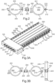
- FIG.1A-1C show schematically a first embodiment of a line protection guide for lines (not shown) that can be moved back and forth.
- This has an elongated, flexible sheath 100, which is composed of a plurality of individual sheath units 101 made of plastic.
- Each sheath unit 101 is made of flexible, soft-elastic plastic, in particular a thermoplastic, e.g. PE, PU, TPU, PTFE, expanded PTFE, PP or the like.
- Each sheath unit 101 has a consistently constant cross-section over its length ( FIG.1B ) perpendicular to the longitudinal direction L.
- the casing unit 101 can be produced inexpensively as a strand using a suitable plastic extrusion technique and cut to a suitable length, e.g.
- the identical casing units 101 form an essentially cylindrical holder 102 inside for the protected routing of a cable, and are designed in a tubular shape with thin-walled wall areas 103 in relation to the cross-section of the holder 102.
- the holders 102 of the flexible casing 100 are spatially separated from one another so that no abrasion can occur between cables guided parallel therein.
- Each casing unit 101 has on one long side a first functional area 110, which FIG.1A-1C consists of two mirror-symmetrically conjugated and separately opposite closure profiles 111, 112, which together form a cross-section approximately in the shape of a T.
- Each closure profile 111, 112 is continuous in the longitudinal direction L and here, for example, approximately L-shaped in cross-section.
- the closure profiles 111, 112 can, as shown here, form L-legs pointing away from one another or L-legs lying parallel next to one another or one inside the other, in order to reduce the height of the closure.
- the casing unit 101 has an interface or opening 113 which is continuous in the longitudinal direction L and radially.
- the gap-shaped opening 113 of a loose or separated casing unit 101 can be widened by bending the sheath unit 101 in order to insert a cable pre-assembled with connectors laterally or transversely to the longitudinal direction L into the receptacle 102 or to remove it from it.
- the casing unit 101 has, diametrically opposite the first functional area 110, a second functional area 120 which consists of a Fastening profile 122.
- the fastening profile 122 is continuous in the longitudinal direction L and has, for example, a substantially C-shaped cross-section with an inner contour 123, which is dimensioned to match the outer contour of the closed closure profiles 101, 112 of the first functional area 110, in particular with a slight undersize for a positive and non-positive connection.
- the functional areas 110, 120 define, here together with the opening 113, through their symmetrical longitudinal section plane the neutral fiber of the flexible casing 100, i.e. the longitudinal section plane, the length of which when bent or in the deflection curve 4 ( FIG.8 ), ie it does not exhibit any tensile/shear stress.
- the additional wall thickness in the functional areas 110, 120 results in a comparatively stable and more controlled moving casing 100 without noticeably impairing its reversible flexibility.
- FIG.1A and FIG.1C further show one of two end clamping devices 130 with two clamping parts 131, 132, between which all the casing units 101 of the casing 100, including the cables (not shown) guided therein, are sealed dust-tight at the end and in the axial direction, e.g. by means of clamping screws.
- the clamping devices 130 can also achieve strain relief for the cables (not shown) and can be constructed in a manner known per se, e.g. similar to the teachings of DE 10 2012 100 290 B4 , be carried out.
- FIG.1A shows one of two support chains 135 which is accommodated in the receptacles 102 of the two laterally outer casing units 101 and consists of individual chain links.
- Optional support chains 135 can, on the one hand, protect against buckling by reducing the minimum permissible radius of the deflection curve 4 ( FIG.8 ) and on the other hand, by attaching the chain links in the extended position, the unsupported length of the sheath 100 in the movable strand, e.g. in the upper strand 1 ( FIG.8 ), enlarge.
- the opposite Closure profiles 111, 112 are connected in one piece to the pipe segment-like wall areas 103 of the casing unit 101.
- the fastening profile 122 is also connected in one piece to the upper wall area 103 and to the lower wall area 103.
- the closure profiles 111, 112 can, as an alternative to a cost-saving, uniform material production in one piece, be manufactured separately from a suitable plastic and bonded to wall areas 103 or the casing units 101 to form a material composite, preferably by plastic welding.
- the cross section of the casing units 101 or wall areas 103 can have an elongated round or oval shape in addition to the approximately circular shape shown.
- the cross-sectional shapes of the closure profiles 111, 112 and the fastening profile 122 shown are purely exemplary and can be designed differently, e.g. predominantly rounded.
- the number of parallel coupled shell units 101 according to FIG.1A-1C can be freely selected to suit the number of cables required or can be subsequently extended thanks to the functional areas 110, 120.
- the closure profiles 111, 112 can also be designed on the inside of the opening (not shown here) as a pressure closure, e.g. according to the Ziploc ® principle, or similar, in order to avoid undesirable widening of the opening 113 after separating the adjacent casing unit 101 (see also FIG.4A-4D ).
- FIG.1A-1C also show a closing strip 105 with an inner contour corresponding to the fastening profile 122.
- the closing strip 105 serves to tightly close the opening 113 (with regard to the escape of abrasion particles) or the closing profiles 111, 112 located on an outer side of a laterally outer casing unit 101, analogous to the fastening profile 122.
- FIG.1C illustrates the completely closed operating state of the casing 100, in which all fastening profiles 122 are connected in a form-fitting manner and/or by force-fitting, e.g. clamping effect, to the opposite and closed closure profiles 111, 112 and close the intermediate opening 113 in the longitudinal direction L continuously and dust-tight.
- FIG.1 corresponding or identical structure or function in FIG.2-7 corresponding reference symbols and may not be described repeatedly.
- FIG.2 shows a preferred, alternative casing unit 201 with two functional areas 210, 220 for constructing a casing ( FIG.1A-1C
- the cover unit 201 differs from FIG.1A-1C mainly due to the different cross-sectional shape of the fastening profile 222 in the second functional area 220.
- the fastening profile 222 is in FIG.2 as a positive form or male form-fitting part with a cross-section, e.g. in T-shape, up to the interface or opening 213 and corresponding to the cross-section of the first functional area 210.
- the casing unit 201 has to both longitudinal center planes, in FIG.2 vertically and horizontally, a largely symmetrical cross-section, except for the one-sided opening 213.
- the second functional area 220 could be manufactured identically to the first functional area 210, ie fully symmetrical with an opening 213 on both sides.
- the casing unit 201 would be composed of two identical half shells (not shown), which can be manufactured, for example, by injection molding.
- cover unit 201 allows separation without opening the adjacent cover unit 201. This is achieved by fastening adjacent cover units 201 ( FIG.1C ) is achieved using a separate fastening strip 204.
- the fastening strip 204 has a symmetrical, uniform cross-section throughout, e.g. in an H-shape or double C-shape.
- the fastening strip 204 has an inner contour 223 on both sides that matches both functional areas 210, 220, here as a negative form or female form-fitting part.
- the fastening strip 204 can detachably connect two casing units 201 by form-fitting and/or force-fitting, as FIG.2 At the same time, the fastening strip 204 together with the functional area 210 serves as a closure for dust-tight closing of the opening 213 between the closure profiles 211, 212.
- Other cross sections, in particular the functional areas 210, 220 and the fastening strip 204, can also use the principle of FIG.2 appropriately implemented.
- FIG.3A-3B show another advantage of the symmetrical design the hull unit 201 from FIG.2 .
- an identical support device 240 can be attached for supporting and guiding the casing units in a defined manner at the functional areas 210, 220, as FIG.3B
- the support device 240 has a support band 244 with a cross-section corresponding to the fastening strip 204, ie matching the cross-section of the functional areas 210, 220, e.g. grooves on both sides with inner contour 223.
- the support device 240 is designed to cover the deflection radius of the deflection bend 4 ( FIG.8 ) and to support a self-supporting strand 1 in the extended position, or to increase the possible self-supporting length of the strand 1.
- the support device 240 has T-shaped stop elements 245 formed transversely to the longitudinal direction L on both sides with the support band 244 and perpendicular thereto, with T-arms 246, 247 standing in the longitudinal direction L of the casing 200.
- the top/bottom or inner/outer T-arms 246, 247 are dimensioned to different lengths, so that the T-arms 247 in the deflection curve 4 stop radially on the inside at the desired radius or the T-arms 246 are in the stop in the extended position.
- the support band 244 is preferably located, like the fastening strip 204, at the level of the neutral fiber of the flexible sheath 200.
- the fastening strip 204 and the support device 240 are made of flexible, flexurally elastic plastic(s). They do not rub against the cables and can therefore, if required, have a higher flexural rigidity than the sheath units 201, for example to maintain a radius in the deflection curve 4 or to increase the self-supporting length. Further details on the design of the support device 240 can be found, with the exception of the shape of the support band 244, in the teaching from WO 2008/125087 A1 are equivalent to.
- FIG.1-2 Each casing unit 101; 201 forms exactly one receptacle 102; 202 for one or possibly several lines.
- FIG.4-6 show embodiments in which the casing 400 is a one-piece casing unit 401; 601 with subdivisions for forming several parallel receptacles 402; 602 in the same casing unit 401; 601.
- FIG.4-5 show an alternative, one-piece cover unit 401 with For example, three parallel receptacles 402, each of which can be opened individually ( FIG.4A ) and closed ( FIG.4C ) in order to insert or replace cables.
- the casing unit 401 is a one-piece flexible plastic profile with a constant cross-section in the longitudinal direction L, as shown in FIG.4 illustrated. It can be manufactured from one piece by extrusion, for example. Manufacturing and material-related advantages can arise if the functional areas, in particular closure profiles 411, 412, are manufactured separately and possibly from a particularly suitable other plastic and are subsequently connected to the wall areas in one piece. A multi-component manufacturing process is also conceivable.
- the casing unit 401 has two functional areas 420, 421 on both sides, which can be used to connect adjacent casing units 401 in parallel, as shown in FIG.5
- the functional areas 420, 421 have in FIG.4-5 with the casing unit 401 one-piece fastening profiles 422, 425 which are designed for form and force locking with conjugated interlocking cross-section, e.g. similar FIG.1 .
- the fastening profile 425 on the side to be opened is in two parts with an intermediate interface, e.g. analogous to the functional area 110 of FIG.1A-1C , with an outer contour matching the inner contour 423 of the fastening profile 422.
- fastening using separate fastening strips analogous to FIG.2-3 possible.
- FIG.4A shows in more detail, on one side of each of the several receptacles 402 of the same casing unit 401, a functional area 410 with an opposite pair of cooperating closure profiles 411, 412 is connected in one piece to the casing unit 401.
- the closure profiles 411, 412 also extend in the longitudinal direction L with a constant cross-section and serve to tightly close (with regard to particle size) the respective associated receptacle 402 ( FIG.4C ).
- the closure profiles 411, 412 can be designed as a closure strip comprising at least positively interlocking profile elements 414, e.g. with a barb shape in cross section, according to the principle of a suitable pressure closure, or the like.
- Support areas 415 serve for the positive locking of the Profile elements 414 in the closed state ( FIG.4C ).
- the receptacles 402 can be opened individually and tightly closed as required. Opening can be achieved by bending up the flexible wall area 403.
- FIG.4-5 show a functional area 410 which is designed as a robust double closure with two profile elements 414 on each closure profile 411, 412, e.g. to prevent unwanted opening during operation. However, unwanted opening can already be avoided if the wide side of the casing 400 to be opened is located radially inside in the deflection curve 4.
- the interface of the opening 413 between the closure profiles 411, 412 is arranged at the level of the neutral fiber, cf. FIG.4C .
- FIG.5 shows a casing 500 made of two casing units 401, which are detachably and parallel fastened to one another by means of their lateral functional areas 420, 421 or their fastening profiles 422, 425.
- a support chain 135 can be inserted, as shown in FIG.1A described, arranged.
- the 701 shell units cannot be opened without causing damage This means that cables must be installed in the same way as FIG.1-6 , axially or in the longitudinal direction. This can prevent particles from accidentally escaping during maintenance work. Simplification of maintenance and expandability is achieved with the casing units 701, without a locking function on the receptacles 702, solely through the concept of the fastening function or only functional areas 720, 721 that work together for the parallel fastening of individual casing units 701.
- the sheath 100 is designed as a tube and is sufficiently flexible, among other things through a suitable design and/or choice of material, in order to allow a reversibly flexible curvature of the deflection bend 4 with little effort and to follow the travel movement of the movable connection 7 with the least possible resistance.
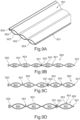
- the lens-shaped cross-section is preferred according to FIG.9A-9D used to design the receptacles 902. This can be formed in particular from two equal circular segments which are assembled symmetrically to the neutral fiber at their chords. This cross-sectional shape reduces the formation of folds, ie abrasion in the deflection curve.
- the casing units 901 are at least predominantly made of flexible, permanently elastic, bendable plastic, in particular extruded, eg from expanded PTFE.
- hull units 901 after FIG.9A-9D cannot be opened without causing damage, ie, unlike with FIG.1-6 , axially or in the longitudinal direction. However, this can reliably prevent unwanted particles from escaping during maintenance work.
- Maintenance and expandability are simplified with the casing units 901, without a locking function on the receptacles 902, solely through the concept of the fastening function or the functional areas 920, 921 that work together to fasten individual casing units 901 in parallel.
- Each casing unit 901 can, for example, have a related cable harness in order to renew a cable harness pre-assembled with plugs or the like independently of a different cable harness by replacing a casing unit 901.
- Each hull unit 901 after FIG.9A-9D has functional areas 920, 921 diametrically opposite each other on both sides and either manufactured in one piece with the closed shell wall 903 or subsequently connected to it and extending continuously in the longitudinal direction L.
- the functional areas 920, 921 each have a fastening profile and/or a fastening strip as a fastening band for a detachable connection by form fit and/or force fit.
- the functional areas 920, 921 are designed to work together, for the required detachment or attachment of a shell unit 901 to or from an adjacent shell unit 901.
- a suitable construction is to FIG.10A-10D explained below.
- FIG.9B-9D show two connected casing units 901 by way of example, wherein a first casing unit 901 forms three receptacles 902.
- a second casing unit 901 also has three receptacles 902.
- the second casing unit 901 has two receptacles 902 and in FIG.9D a receptacle 902.
- a line harness not shown
- an individual line harness not shown
- the functional areas 920, 921 are preferably manufactured in one piece with the casing walls 903 using an extrusion process, either from the same material or from different plastics, e.g. with a flexible but firmer or harder plastic for the functional areas 920, 921.
- the functional areas 920, 921 can be manufactured separately, e.g. by extrusion or injection molding, and connected in one piece with the rest of the profile of the casing unit 901, e.g. by welding them continuously in the longitudinal direction using a suitable technique.
- the casing wall 903 and the functional areas 920, 921 are preferably manufactured from a thermoplastic.
- FIG.10A-10D show a particularly preferred further example of a casing unit 1001, which is a variant of the principle of FIG.4A-4D
- the casing unit 1001 is also made of flexible plastic, preferably extruded, and has several, eg three, receptacles 1002 for lines 6 in the closed state ( FIG.10B ).
- the casing unit 1001 has a separate or assigned 1010 functional area for each receptacle 1002, which is designed as a closure, here in particular as a band-like closure strip with two conjugated interlocking closure profiles or engagement profiles, namely a hook profile 1011 that can engage in a claw profile 1012.
- the hook profile 1011 and the claw profile 1012 are each provided with at least one undercut, preferably two symmetrical undercuts, and engage with each other with a barb function, ie they are relatively easy to close or connect but can only be released with significantly greater force.
- the casing unit 1001 also has a functional area 1020 or 1021 on each of the two opposite narrow sides, which is used for the modular fastening of several casing units 1001 with correspondingly identical functional areas 1020 or 1021 in a position side by side or on a support device (cf. FIG.3A ).
- the fastening straps or strips 1020, 1021 are also designed as claw profiles 1022 or hook profiles 1025, similar or identical to the locking functional areas 1010.
- FIG.10C-10D show schematic enlarged cross-sectional views of the hook profile 1011 and the claw profile 1012, which can also be used for the closure functional areas 1020 and 1021.
- the hook profile 1011 and the claw profile 1012 have in the longitudinal direction (perpendicular to the plane of the FIG.10C-10D ) of a constant cross-section and are designed as flexible strips or bands, which in the deflection bend 4 ( FIG.4 ) are flexible around the axis A.
- the hook profile 1011 is designed as a symmetrical double hook profile with respect to the neutral fiber N, e.g. as shown here in arrowhead shape, mushroom head shape or similar and has corresponding rear undercuts or undercuts.
- a hook profile 1011 or a claw profile 1012 in particular as known from toothless zippers, in particular pull, slide or pressure fasteners, made of plastic, are also possible.
- the above design is analogously applicable to the fastening functional areas 1020, 1021.
- Zippers 1010 or 1020, 1021 with interlocking parts that have a substantially uniform cross-section over their entire length and are operated without a slider are preferred, since this design can be easily implemented using the extrusion process.
- a suitable slider can also be provided as a tool or aid for opening or closing.
- the neutral fiber N also called zero line, is the layer of the cross-section whose length changes during bending, especially when moving the deflection bend 4 ( FIG.8 ), ie the layer which maintains a constant dimension in the longitudinal direction when bent.
- the fastening functional areas 1020 and 1021 can be connected to one another relatively easily in a connection direction V which is perpendicular to the longitudinal direction L, whereby the connection direction V can essentially lie in the plane of the neutral fiber N. Contrary to the direction V, however, the fastening functional areas 1020 and 1021 are very difficult to detach, so that no unintentional detachment occurs during operation.
- the closure functional areas 1010 and fastening functional areas 1020 and 1021 can be made of the same material as the walls of the receptacles 1002 or from a comparatively more rigid plastic, e.g. in a coextrusion process, for example in order to increase the stability of the connections and the casing unit 1001 as a whole.
- FIG.11 shows a modification with a casing unit 1101, in which the fastening functional areas 1120 and 1121 are formed according to the principle of FIG.10A-10D
- the locking functional areas 1110 are designed as double hook engagement profiles according to the principle of FIG.4A-4C
- the representation in FIG.4A-4C is not to scale, since the closure functional areas 410 are shown greatly enlarged there.
- the functional areas 1010, 1020 or 1021 or 1110, 1120 or 1121 have a cross-sectional height in the millimeter range, e.g. from approx. 1mm to approx. 3mm.
- FIG.14 shows a further development, with casings 1402 each with only one receptacle 1402, in which closure profiles 1411, 1412 are provided as closure strips, each having two interacting, form-fitting interlocking profile elements 1414.
- closure profiles 1411, 1412 are provided as closure strips, each having two interacting, form-fitting interlocking profile elements 1414.
- These profile elements 1414 are designed, for example, with a barb shape in cross-section, according to the principle of a suitable pressure closure or the like, analogous to FIG.4A or FIG.6 .
- the holders 1402 can also be opened individually and closed dust-tight if required to replace a cable or support chain.
- the locking profiles 1411, 1412 have a double
- connection direction V of the fastening profiles 1421, 1422 is not in the neutral fibre, but is directed perpendicular to the neutral fibre N, and also lies in the plane perpendicular to the longitudinal direction, as FIG.14B illustrated.
- FIG.15 a comparable construction in the assembled state, in which each casing 1501 is composed of two half-shells 1503A, each of which has two closure profiles 1511, 1512 and only one fastening profile 1521.
- the locking profiles 1611, 1612 correspond to those from FIG.14-15 or FIG.4 or FIG.6
- the fastening straps 1621, 1622 have the hook and claw profile made of FIG.9 or FIG.10C-10D .
- FIG.17 shows FIG.17 in an enlarged schematic diagram, another functional profile with interacting functional areas 1711, 1712 according to the principle of a suitable push or pull fastener.
- the individual hook strips or fastener profile elements 1714 are shown in cross section identical, each designed with a mirror-symmetrical mushroom head or double T shape or similar and interlocking in double rows like hooks or one behind the other.
- separate support areas 415 are provided as in FIG.4 not required.
- the functional areas 1711, 1712 from FIG.17 can, such as in FIG.14-15 , can also be used as fastening profiles.
- a locking slide 750 (cf. FIG.7B ) should be provided.
- FIG.18A-18B show various arrangements of enclosures with enclosure units 901, eg analogous to FIG.9 .
- the two outer, lateral casing units 901 are specifically assigned to two schematically shown support chains 135, so that they can be exchanged separately with their associated casing 901.
- FIG.18B shows that the sheaths 901B assigned to the support chains 135, e.g. for more robust, larger support chains 135, have a comparatively larger free cross-section than the cable-carrying sheath 901A.
- FIG.19 illustrates a multilayer structure with several sheaths 900-1... 900-5, in which sheath units 900 according to the invention, e.g. FIG.9A-9D can be used, whereby some covers 901B are provided separately for support chains 135, e.g. in the lower, inner layer 900-5 in the deflection bend.
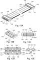
- FIG.13A-13E finally show a generic flexible sheath 1300 for clean room applications according to an independent invention, which preferably but not necessarily according to one of the teachings of FIG.1-12
- the casing 1300 is designed according to the principle of FIG.8
- the two end areas 1305, 1307 of the casing 1300 are connected at the ends using identical clamping devices 1330, e.g. to a fixed point and a movable connection point (cf. FIG.8 ).
- the clamping device 1330 represents a further development of the principle FIG.1A or FIG.3A
- Each clamping device 1330 has a first clamping part 1331 and a second clamping part 1332.
- Each clamping part 1331, 1332 is made in the form of a plate, e.g. as a molded part made of metal, and has an inner recess or receptacle 1333 for the corresponding end area 1305 or 1307.
- the roughly rectangular clamping parts 1331, 1332 each have two opposite end faces 1334, 1335 which run transversely, here perpendicularly to a feed-through direction of the cables or the longitudinal direction L, according to which casing 1300 is inserted in the respective clamping device 1330.
- each recess or receptacle 1333 opens outwards on both sides in the longitudinal direction L, ie on both end faces 1334, 1335, so that cables can be passed through unhindered.
- both clamping parts 1331, 1332 are preferably of identical construction and differ only with regard to the screw connection for clamping both clamping parts 1331, 1332 against each other in the assembled state ( FIG.13A or FIG.13C ).
- the pressure pieces 1340 When the clamping device 1300 is closed, the pressure pieces 1340 are pressed against the corresponding end area 1305, 1307 of the cable protection guide or casing 1300 and hold it in a force-locking manner in the longitudinal direction. In addition, the pressure pieces 1340 ensure a dust-tight seal or serve as sealing profiles to prevent particles from escaping at the open end of the casing 1300.
- each pressure piece 1340 is made of a plastic that is more compressible or softer than the material of the clamping parts 1331, 1332, in particular soft-elastic or rubber-elastic or possibly also hard-elastic, in particular as a hollow chamber extrusion profile here with two hollow spaces 1345 that are oval or pointed oval in cross section ( FIG.13E ).
- the desired deformability of the pressure piece 1340 can also be achieved in other ways by material selection and/or shape.
- each pressure piece 1340 is designed to be deformable when the clamping parts 1331, 1332 are pressed or tightened and serves, among other things, as a strain relief for the cables (not in FIG.13A-13E shown).
- FIG.13D The best way to show this is to show each printed piece 1340 as dimensioned and/or arranged such that it protrudes or protrudes in the feed-through direction or longitudinal direction L, in particular with a corresponding narrow side 1344, over the respective end face 1334 or 1335 of the associated clamping part 1331 or 1332.
- This ensures that the respective pressure piece 1340 provides corner protection on the corresponding end face to soften the edges, so that the cable protection guide or casing 1300 does not come into contact with the edge of the respective end face 1334 or 1335.
- This is particularly the case with the end face 1335 ( FIG.13A ) is advantageous, at which the sheath 1300 is introduced or inserted into the clamping device 1330.
- the pressure pieces 1340 protrude over the critical front side 1335 of the associated clamping part 1331 or 1332 and at least in the assembled state in a protective manner.
- the edge of the front side 1335 facing the casing 1300 can also be partially encompassed or covered, but this is only possible if there is a sufficiently protective projection in the longitudinal direction (cf. FIG.13D ) is not necessary, since the pressure pieces 1340 already create a softer transition.
- a material pairing that is more favorable in terms of abrasion can be achieved compared to the rigid material, usually metal, of the clamping parts 1331 or 1332.
- the plastic of the pressure pieces 1340 can in particular be harder or less soft-elastic than the plastic of the casing 1300.
- a protrusion of the pressure pieces 1340 on the opposite free front side 1334 is also advantageous for protecting cables leading out of the cable routing there and for improving the sealing effect against particle escape.
- each pressure piece 1340 in the unloaded state forms on the inside facing away from the clamping part, in cross section ( FIG.13D ), at least one or more convexly curved or bulged surfaces 1342 in order to provide the smoothest possible transitions or interfaces on the outside of the casing.
- each pressure piece 1340 can extend with their longitudinal extension perpendicular to the feed-through direction L over the entire width of the recess 1330, as in FIG.13B
- each pressure piece 1340 further has two rounded narrow sides 1344.
- each pressure piece 1340 can be designed as symmetrical profiles at low cost and to simplify assembly.
- each pressure piece can have a protruding, e.g. toothed, fastening rib 1346 on the back for attachment in a transverse groove of the clamping part ( FIG.13D ).
- each clamping part 1331, 1332 two identical pressure pieces 1340 are arranged next to each other in parallel with a distance ( FIG.13D ) so that they run perpendicular to the feed-through direction, ie the longitudinal direction L of the casing 1300.
- the proposed pressure pieces 1340 in the clamping devices 1300 offer not only corner protection between the clamping parts 1331, 1332 - in particular their front sides 1335 facing the inside of the deflection bend - and the casing 1300, but also better protection of the cables as well as reliable modular sealing against particle escape and/or end-side strain relief of the cables for different cable diameters.
- the pressure pieces 1340 thus reduce the number of required components and simplify assembly.
Landscapes
- Engineering & Computer Science (AREA)
- General Engineering & Computer Science (AREA)
- Mechanical Engineering (AREA)
- Architecture (AREA)
- Civil Engineering (AREA)
- Structural Engineering (AREA)
- Electric Cable Arrangement Between Relatively Moving Parts (AREA)
- Protection Of Pipes Against Damage, Friction, And Corrosion (AREA)
- Package Frames And Binding Bands (AREA)
- Details Of Indoor Wiring (AREA)
- Supports For Pipes And Cables (AREA)
- Clamps And Clips (AREA)
- Slide Fasteners (AREA)
Applications Claiming Priority (4)
| Application Number | Priority Date | Filing Date | Title |
|---|---|---|---|
| DE202019100169.0U DE202019100169U1 (de) | 2019-01-14 | 2019-01-14 | Kompakte flexible Leitungsschutzführung, insbesondere für Reinraumanwendungen |
| DE202019103276.6U DE202019103276U1 (de) | 2019-06-11 | 2019-06-11 | Kompakte Leitungsschutzführung für Reinraumanwendungen sowie Hülleinheit und Klemmvorrichtung hierfür |
| PCT/IB2020/000047 WO2020148596A1 (fr) | 2019-01-14 | 2020-01-14 | Guide de protection de lignes/conduits compact pour applications en salle blanche, ainsi que unité d'enveloppe et dispositif de serrage associés |
| EP20717249.5A EP3912243B1 (fr) | 2019-01-14 | 2020-01-14 | Guide de protection de lignes/conduits compact pour applications en salle blanche, ainsi que unité d'enveloppe et dispositif de serrage associés |
Related Parent Applications (1)
| Application Number | Title | Priority Date | Filing Date |
|---|---|---|---|
| EP20717249.5A Division EP3912243B1 (fr) | 2019-01-14 | 2020-01-14 | Guide de protection de lignes/conduits compact pour applications en salle blanche, ainsi que unité d'enveloppe et dispositif de serrage associés |
Publications (2)
| Publication Number | Publication Date |
|---|---|
| EP4477927A2 true EP4477927A2 (fr) | 2024-12-18 |
| EP4477927A3 EP4477927A3 (fr) | 2025-05-14 |
Family
ID=69172796
Family Applications (3)
| Application Number | Title | Priority Date | Filing Date |
|---|---|---|---|
| EP20717249.5A Active EP3912243B1 (fr) | 2019-01-14 | 2020-01-14 | Guide de protection de lignes/conduits compact pour applications en salle blanche, ainsi que unité d'enveloppe et dispositif de serrage associés |
| EP20700887.1A Active EP3912242B1 (fr) | 2019-01-14 | 2020-01-14 | Guidage de protection de conducteurs compacte pour des applications en salles propres, ainsi qu'unité de manchon et assemblage comprenant une chaîne d'appui pour celle-ci |
| EP24164611.6A Pending EP4477927A3 (fr) | 2019-01-14 | 2020-01-14 | Guide de protection de ligne compact pour applications en salle blanche, ainsi qu'unité d'enveloppe et dispositif de serrage associés |
Family Applications Before (2)
| Application Number | Title | Priority Date | Filing Date |
|---|---|---|---|
| EP20717249.5A Active EP3912243B1 (fr) | 2019-01-14 | 2020-01-14 | Guide de protection de lignes/conduits compact pour applications en salle blanche, ainsi que unité d'enveloppe et dispositif de serrage associés |
| EP20700887.1A Active EP3912242B1 (fr) | 2019-01-14 | 2020-01-14 | Guidage de protection de conducteurs compacte pour des applications en salles propres, ainsi qu'unité de manchon et assemblage comprenant une chaîne d'appui pour celle-ci |
Country Status (10)
| Country | Link |
|---|---|
| US (3) | US12040570B2 (fr) |
| EP (3) | EP3912243B1 (fr) |
| JP (4) | JP7227383B2 (fr) |
| KR (3) | KR102812541B1 (fr) |
| CN (3) | CN113841312B (fr) |
| CA (1) | CA3126632A1 (fr) |
| DE (1) | DE202020005841U1 (fr) |
| MY (2) | MY206146A (fr) |
| SG (2) | SG11202107736VA (fr) |
| WO (2) | WO2020148596A1 (fr) |
Families Citing this family (13)
| Publication number | Priority date | Publication date | Assignee | Title |
|---|---|---|---|---|
| DE202019103276U1 (de) * | 2019-06-11 | 2020-02-20 | Igus Gmbh | Kompakte Leitungsschutzführung für Reinraumanwendungen sowie Hülleinheit und Klemmvorrichtung hierfür |
| US12040570B2 (en) * | 2019-01-14 | 2024-07-16 | Igus Gmbh | Compact conduit for clean room applications, and casing and clamping fixtures for said conduit |
| US11384869B2 (en) | 2020-03-27 | 2022-07-12 | Pall Corporation | Tube retainers, tube retainer sets, and tube management systems |
| US11519541B2 (en) | 2020-03-27 | 2022-12-06 | Pall Corporation | Tube retainers, tube retainer sets, and tube management systems |
| DE202022102217U1 (de) | 2022-04-25 | 2023-07-26 | Igus Gmbh | Leitungsführungsvorrichtung und Stützkette für Reinraumanwendungen |
| DE102022109963A1 (de) | 2022-04-25 | 2023-10-26 | Igus Gmbh | Verfahren und System zur indirekten Erkennung von Verschleiß einer Leitungsführungseinrichtung bzw. Energieführungskette |
| CN114914756B (zh) * | 2022-05-30 | 2025-07-11 | 国家电网有限公司 | 用于输配电线路的适应不同线径大小的连接金具 |
| DE102023109519A1 (de) | 2023-04-15 | 2024-10-17 | Igus Gmbh | Reinraumtaugliche Leitungsschutzführung für ESD-Schutzzonen |
| CN117220217B (zh) * | 2023-11-08 | 2024-01-26 | 哈尔滨安非科技发展有限公司 | 一种5g基站及其线路归束保护装置 |
| DE202024101891U1 (de) * | 2024-04-16 | 2025-07-18 | Igus Gmbh | Leitungsführungsvorrichtung für Reinraumanwendungen sowie Halteelement dafür |
| CN222301305U (zh) * | 2024-05-20 | 2025-01-03 | 苏州云首软件科技有限公司 | 一种物联网接线用线路整理装置 |
| CN118825718B (zh) * | 2024-09-19 | 2024-11-29 | 温州中穗电气有限公司 | 一种机械连锁插座 |
| CN119009838B (zh) * | 2024-10-18 | 2025-01-24 | 任丘市召明电力设备有限公司 | 一种快装电缆保护管及预埋装置 |
Citations (4)
| Publication number | Priority date | Publication date | Assignee | Title |
|---|---|---|---|---|
| WO2002086349A1 (fr) | 2001-04-23 | 2002-10-31 | Igus Spritzgussteile für die Industrie GmbH | Chaine de guidage d'elements de transport d'energie |
| WO2008125087A1 (fr) | 2007-04-13 | 2008-10-23 | Igus Gmbh | Segment de paroi latérale pour dispositif de guidage de ligne, dispositif de guidage de ligne à segment de paroi latérale, et procédé de production de segment à paroi latérale |
| US8662456B2 (en) | 2011-02-15 | 2014-03-04 | Tsubakimoto Chain Co. | Cable protection and guide device |
| WO2016042134A1 (fr) | 2014-09-18 | 2016-03-24 | Igus Gmbh | Dispositif de guidage de lignes, destiné en particulier à des applications en salle blanche, éléments de coque, et carcasse de support afférente |
Family Cites Families (39)
| Publication number | Priority date | Publication date | Assignee | Title |
|---|---|---|---|---|
| DE907548C (de) | 1951-12-16 | 1954-03-25 | Elektro App K G Gothe & Co | Einfuehrungsstutzen fuer Gummischlauchleitungen, insbesondere fuer ortsveraenderliche Betriebsmittel |
| US3160175A (en) * | 1961-10-02 | 1964-12-08 | Rob Ric Co | Conduit cap and spacer |
| US3399909A (en) * | 1966-02-17 | 1968-09-03 | Honeywell Inc | Transmitting apparatus |
| US4614383A (en) * | 1984-12-31 | 1986-09-30 | General Dynamics, Electronics Division | Cable carrier/retractor |
| DE3507201C1 (de) * | 1985-03-01 | 1989-06-08 | Kabelschlepp Gmbh, 5900 Siegen | Energieleitungstraeger |
| DE8801061U1 (de) * | 1988-01-29 | 1989-06-01 | Robert Bosch Gmbh, 7000 Stuttgart | Leitungsverbund mit flexiblen Leitungssträngen |
| US5134250A (en) * | 1991-04-10 | 1992-07-28 | Panduit Corp. | Wiring duct |
| US6084180A (en) * | 1993-11-15 | 2000-07-04 | Debartolo, Jr.; Joseph V. | Multi-channel duct for power and tel/com conductors |
| JPH11201331A (ja) * | 1998-01-13 | 1999-07-30 | Sumitomo Wiring Syst Ltd | コルゲート管 |
| US6751382B2 (en) | 2000-12-29 | 2004-06-15 | Gateway, Inc. | System for organizing wires and cables |
| JP3349146B1 (ja) | 2001-09-06 | 2002-11-20 | 株式会社椿本チエイン | ケーブル類の保護案内ガイド |
| DE10333834A1 (de) * | 2003-07-24 | 2005-08-11 | Igus Spritzgussteile für die Industrie GmbH | Schiebetürensystem |
| DE202004005848U1 (de) * | 2003-10-15 | 2005-02-24 | Igus Spritzgussteile für die Industrie GmbH | Leitungsführungseinrichtung |
| US7472795B2 (en) * | 2003-12-05 | 2009-01-06 | Pentair Electronic Packaging Company | Anti-sag management assembly |
| US7784259B2 (en) * | 2004-01-23 | 2010-08-31 | A&A Manufacturing Co., Inc. | Monolithic enclosed cable carrier |
| KR100652872B1 (ko) * | 2005-01-03 | 2006-12-01 | 볼보 컨스트럭션 이키프먼트 홀딩 스웨덴 에이비 | 실린더 쿠션장치 |
| EP1713153B1 (fr) | 2005-04-14 | 2008-06-25 | ekd gelenkrohr GmbH | Couplage de ligne |
| US7829797B2 (en) * | 2005-10-17 | 2010-11-09 | Panduit Corp. | Three channel raceway |
| DE102006019133B3 (de) * | 2006-04-21 | 2007-06-28 | Ekd Gelenkrohr Gmbh | Leitungsverbund |
| KR20120088531A (ko) * | 2009-11-27 | 2012-08-08 | 스미토모 덴키 고교 가부시키가이샤 | 소직경 동축 케이블 하니스 및 그 제조 방법 |
| JP4749494B1 (ja) * | 2010-04-02 | 2011-08-17 | 株式会社椿本チエイン | ケーブル類保護案内用多関節支持部材 |
| JP5510046B2 (ja) * | 2010-05-11 | 2014-06-04 | 住友電装株式会社 | ワイヤハーネス用のコルゲートチューブ |
| JP5414704B2 (ja) * | 2011-01-21 | 2014-02-12 | 株式会社椿本チエイン | 多関節型ケーブル類保護案内装置 |
| JP5127943B2 (ja) | 2011-02-10 | 2013-01-23 | サムウォン アクト インコーポレイテッド | 多関節型ケーブル類保護案内装置 |
| JP6021156B2 (ja) | 2013-04-10 | 2016-11-09 | 株式会社椿本チエイン | ケーブル類保護案内装置 |
| DE102013214550B4 (de) | 2013-07-25 | 2022-09-08 | Bayerische Motoren Werke Aktiengesellschaft | Fahrzeug mit einer Heizeinrichtung |
| DE202013105149U1 (de) * | 2013-11-14 | 2013-11-27 | Igus Gmbh | Leitungsführung |
| JP6002656B2 (ja) | 2013-12-04 | 2016-10-05 | 株式会社椿本チエイン | フラット状伝送装置及びその使用方法 |
| JP6317291B2 (ja) | 2015-04-27 | 2018-04-25 | 株式会社椿本チエイン | ケーブル類保護案内装置及び固定部材 |
| TWI556711B (zh) * | 2015-05-05 | 2016-11-01 | King Slide Works Co Ltd | 理線裝置 |
| DE102016000864A1 (de) * | 2016-01-28 | 2017-08-03 | Murrplastik Systemtechnik Gmbh | Energieführungskette |
| WO2017140720A1 (fr) * | 2016-02-16 | 2017-08-24 | Reichle & De-Massari Ag | Dispositif d'étanchéité et procédé de montage d'un dispositif d'étanchéité |
| WO2017181262A1 (fr) * | 2016-04-19 | 2017-10-26 | STM Venture Partners Inc. | Ensembles de conduits à lignes multiples |
| KR101743953B1 (ko) | 2017-01-23 | 2017-06-07 | 성호철 | 다관절형 지지부재를 포함한 케이블 및 적층형 케이블 |
| CN206532631U (zh) * | 2017-03-14 | 2017-09-29 | 太阳电线(东莞)有限公司 | 一种电线电缆保护装置 |
| DE202019103276U1 (de) * | 2019-06-11 | 2020-02-20 | Igus Gmbh | Kompakte Leitungsschutzführung für Reinraumanwendungen sowie Hülleinheit und Klemmvorrichtung hierfür |
| US12040570B2 (en) * | 2019-01-14 | 2024-07-16 | Igus Gmbh | Compact conduit for clean room applications, and casing and clamping fixtures for said conduit |
| DE202019103269U1 (de) * | 2019-06-11 | 2020-07-14 | Igus Gmbh | Leitungsführung mit Stützkette für Reinraumanwendungen und Stützkette hierfür |
| JP7396016B2 (ja) | 2019-12-17 | 2023-12-12 | 株式会社椿本チエイン | ケーブル類保護案内装置 |
-
2020
- 2020-01-14 US US17/310,035 patent/US12040570B2/en active Active
- 2020-01-14 CN CN202080014446.3A patent/CN113841312B/zh active Active
- 2020-01-14 EP EP20717249.5A patent/EP3912243B1/fr active Active
- 2020-01-14 CA CA3126632A patent/CA3126632A1/fr active Pending
- 2020-01-14 KR KR1020217025850A patent/KR102812541B1/ko active Active
- 2020-01-14 MY MYPI2021003963A patent/MY206146A/en unknown
- 2020-01-14 EP EP20700887.1A patent/EP3912242B1/fr active Active
- 2020-01-14 KR KR1020217025851A patent/KR102797348B1/ko active Active
- 2020-01-14 WO PCT/IB2020/000047 patent/WO2020148596A1/fr not_active Ceased
- 2020-01-14 US US17/310,061 patent/US11811154B2/en active Active
- 2020-01-14 MY MYPI2021003985A patent/MY203229A/en unknown
- 2020-01-14 DE DE202020005841.6U patent/DE202020005841U1/de active Active
- 2020-01-14 JP JP2021540483A patent/JP7227383B2/ja active Active
- 2020-01-14 CN CN202311511552.4A patent/CN117767189A/zh active Pending
- 2020-01-14 EP EP24164611.6A patent/EP4477927A3/fr active Pending
- 2020-01-14 WO PCT/EP2020/050842 patent/WO2020148300A1/fr not_active Ceased
- 2020-01-14 KR KR1020257016644A patent/KR20250079049A/ko active Pending
- 2020-01-14 JP JP2021540482A patent/JP7496827B2/ja active Active
- 2020-01-14 SG SG11202107736VA patent/SG11202107736VA/en unknown
- 2020-01-14 CN CN202080020668.6A patent/CN113661622B/zh active Active
- 2020-01-14 SG SG11202108321SA patent/SG11202108321SA/en unknown
-
2023
- 2023-02-08 JP JP2023017996A patent/JP7509935B2/ja active Active
-
2024
- 2024-06-13 US US18/741,914 patent/US12438300B2/en active Active
- 2024-06-20 JP JP2024099233A patent/JP7764543B2/ja active Active
Patent Citations (5)
| Publication number | Priority date | Publication date | Assignee | Title |
|---|---|---|---|---|
| WO2002086349A1 (fr) | 2001-04-23 | 2002-10-31 | Igus Spritzgussteile für die Industrie GmbH | Chaine de guidage d'elements de transport d'energie |
| WO2008125087A1 (fr) | 2007-04-13 | 2008-10-23 | Igus Gmbh | Segment de paroi latérale pour dispositif de guidage de ligne, dispositif de guidage de ligne à segment de paroi latérale, et procédé de production de segment à paroi latérale |
| US8662456B2 (en) | 2011-02-15 | 2014-03-04 | Tsubakimoto Chain Co. | Cable protection and guide device |
| DE102012100290B4 (de) | 2011-02-15 | 2015-07-02 | Tsubakimoto Chain Co. | Gelenkige Schutz- und Führungsvorrichtung für Kabel und Schläuche |
| WO2016042134A1 (fr) | 2014-09-18 | 2016-03-24 | Igus Gmbh | Dispositif de guidage de lignes, destiné en particulier à des applications en salle blanche, éléments de coque, et carcasse de support afférente |
Also Published As
Similar Documents
| Publication | Publication Date | Title |
|---|---|---|
| EP3912243B1 (fr) | Guide de protection de lignes/conduits compact pour applications en salle blanche, ainsi que unité d'enveloppe et dispositif de serrage associés | |
| EP3195434B1 (fr) | Dispositif de guidage de lignes, destiné en particulier à des applications en salle blanche, éléments de coque, et carcasse de support afférente | |
| EP0490022B1 (fr) | Dispositif de guidage de câbles | |
| DE202019103276U1 (de) | Kompakte Leitungsschutzführung für Reinraumanwendungen sowie Hülleinheit und Klemmvorrichtung hierfür | |
| DE19915035C2 (de) | Leitungsführungselement zum Führen wenigstens einer Leitung | |
| EP2614563B1 (fr) | Bâti pour systèmes de passe-câbles et pièces pour ce bâti | |
| DE3640226C2 (fr) | ||
| DE102007040812A1 (de) | Kabelschutz- und -führungsvorrichtung vom Falttyp | |
| DE19710489A1 (de) | Faltbares Schutzelement für Leitungen | |
| EP3984105A1 (fr) | Structure de guidage de ligne comportant une chaîne de support conçue pour des applications en salle blanche, et chaîne de support | |
| EP4136374A2 (fr) | Fixation d'extrémité d'une gaine flexible destinée à des applications en salle blanche | |
| DE102015110162A1 (de) | Energieführungskette | |
| DE202014104458U1 (de) | Energieführungseinrichtung insbesondere für Reinraumanwendungen | |
| DE10142628C2 (de) | Verschluss- und Abdichtelement | |
| DE202019100169U1 (de) | Kompakte flexible Leitungsschutzführung, insbesondere für Reinraumanwendungen | |
| EP4073893B1 (fr) | Appareil de guidage de conducteurs et fixations d'extrémités modulaires à couvercle flexible pour applications en salle propre | |
| EP1729389A1 (fr) | Dispositif de guidage de conduites flexibles électriques ou à fluide | |
| WO2023247071A1 (fr) | Segment de protection et dispositif de protection pour des conduites | |
| DE102021002202A1 (de) | Flexibler schlauch, insbesondere staubsaugerschlauch | |
| EP4208654B1 (fr) | Chaîne de transmission d'énergie à subdivision interne de protection de câble, et maillon de chaîne et module de structure associés | |
| EP3976993B1 (fr) | Chaîne porte-câbles pour applcation salle blanche | |
| DE202009002018U1 (de) | Installationsteil | |
| WO2026087767A1 (fr) | Guide de câble pour la protection d'au moins un câble | |
| DE1816307A1 (de) | Verfahren zur Befestigung oder Verbindung von Seilen und eine nach dem Verfahren hergestellte Befestigungs- bzw.Verbindungsvorrichtung | |
| DE202019106980U1 (de) | Endbefestigung, Stützkette und Kettenglied einer Leitungsführung für Reinraumanwendungen |
Legal Events
| Date | Code | Title | Description |
|---|---|---|---|
| PUAI | Public reference made under article 153(3) epc to a published international application that has entered the european phase |
Free format text: ORIGINAL CODE: 0009012 |
|
| STAA | Information on the status of an ep patent application or granted ep patent |
Free format text: STATUS: THE APPLICATION HAS BEEN PUBLISHED |
|
| AC | Divisional application: reference to earlier application |
Ref document number: 3912243 Country of ref document: EP Kind code of ref document: P |
|
| AK | Designated contracting states |
Kind code of ref document: A2 Designated state(s): AL AT BE BG CH CY CZ DE DK EE ES FI FR GB GR HR HU IE IS IT LI LT LU LV MC MK MT NL NO PL PT RO RS SE SI SK SM TR |
|
| REG | Reference to a national code |
Ref country code: DE Ref legal event code: R079 Free format text: PREVIOUS MAIN CLASS: F16L0003015000 Ipc: H02G0011000000 |
|
| RIC1 | Information provided on ipc code assigned before grant |
Ipc: F16L 3/015 20060101ALN20250115BHEP Ipc: F16G 13/18 20060101ALN20250115BHEP Ipc: H02G 3/04 20060101ALI20250115BHEP Ipc: F16G 13/16 20060101ALI20250115BHEP Ipc: H02G 11/00 20060101AFI20250115BHEP |
|
| PUAL | Search report despatched |
Free format text: ORIGINAL CODE: 0009013 |
|
| AK | Designated contracting states |
Kind code of ref document: A3 Designated state(s): AL AT BE BG CH CY CZ DE DK EE ES FI FR GB GR HR HU IE IS IT LI LT LU LV MC MK MT NL NO PL PT RO RS SE SI SK SM TR |
|
| RIC1 | Information provided on ipc code assigned before grant |
Ipc: F16L 3/015 20060101ALN20250407BHEP Ipc: F16G 13/18 20060101ALN20250407BHEP Ipc: H02G 3/04 20060101ALI20250407BHEP Ipc: F16G 13/16 20060101ALI20250407BHEP Ipc: H02G 11/00 20060101AFI20250407BHEP |
|
| STAA | Information on the status of an ep patent application or granted ep patent |
Free format text: STATUS: REQUEST FOR EXAMINATION WAS MADE |
|
| 17P | Request for examination filed |
Effective date: 20251111 |
|
| RAP3 | Party data changed (applicant data changed or rights of an application transferred) |
Owner name: IGUS SE & CO. KG |
|
| STAA | Information on the status of an ep patent application or granted ep patent |
Free format text: STATUS: EXAMINATION IS IN PROGRESS |