EP4477933A1 - Système d'étanchéité pour segments de tuyau et procédé de fabrication d'un système d'étanchéité - Google Patents
Système d'étanchéité pour segments de tuyau et procédé de fabrication d'un système d'étanchéité Download PDFInfo
- Publication number
- EP4477933A1 EP4477933A1 EP24182505.8A EP24182505A EP4477933A1 EP 4477933 A1 EP4477933 A1 EP 4477933A1 EP 24182505 A EP24182505 A EP 24182505A EP 4477933 A1 EP4477933 A1 EP 4477933A1
- Authority
- EP
- European Patent Office
- Prior art keywords
- sealing system
- sealing
- sliding layer
- region
- area
- Prior art date
- Legal status (The legal status is an assumption and is not a legal conclusion. Google has not performed a legal analysis and makes no representation as to the accuracy of the status listed.)
- Pending
Links
Images

Classifications
-
- F—MECHANICAL ENGINEERING; LIGHTING; HEATING; WEAPONS; BLASTING
- F16—ENGINEERING ELEMENTS AND UNITS; GENERAL MEASURES FOR PRODUCING AND MAINTAINING EFFECTIVE FUNCTIONING OF MACHINES OR INSTALLATIONS; THERMAL INSULATION IN GENERAL
- F16L—PIPES; JOINTS OR FITTINGS FOR PIPES; SUPPORTS FOR PIPES, CABLES OR PROTECTIVE TUBING; MEANS FOR THERMAL INSULATION IN GENERAL
- F16L21/00—Joints with sleeve or socket
- F16L21/02—Joints with sleeve or socket with elastic sealing rings between pipe and sleeve or between pipe and socket, e.g. with rolling or other prefabricated profiled rings
- F16L21/035—Joints with sleeve or socket with elastic sealing rings between pipe and sleeve or between pipe and socket, e.g. with rolling or other prefabricated profiled rings placed around the spigot end before connection
-
- E—FIXED CONSTRUCTIONS
- E03—WATER SUPPLY; SEWERAGE
- E03F—SEWERS; CESSPOOLS
- E03F3/00—Sewer pipe-line systems
- E03F3/04—Pipes or fittings specially adapted to sewers
-
- F—MECHANICAL ENGINEERING; LIGHTING; HEATING; WEAPONS; BLASTING
- F16—ENGINEERING ELEMENTS AND UNITS; GENERAL MEASURES FOR PRODUCING AND MAINTAINING EFFECTIVE FUNCTIONING OF MACHINES OR INSTALLATIONS; THERMAL INSULATION IN GENERAL
- F16J—PISTONS; CYLINDERS; SEALINGS
- F16J15/00—Sealings
- F16J15/02—Sealings between relatively-stationary surfaces
- F16J15/021—Sealings between relatively-stationary surfaces with elastic packing
- F16J15/022—Sealings between relatively-stationary surfaces with elastic packing characterised by structure or material
- F16J15/024—Sealings between relatively-stationary surfaces with elastic packing characterised by structure or material the packing being locally weakened in order to increase elasticity
- F16J15/027—Sealings between relatively-stationary surfaces with elastic packing characterised by structure or material the packing being locally weakened in order to increase elasticity and with a hollow profile
Definitions
- the present invention relates to a sealing system for pipe segments and a method for producing a sealing system.
- the present invention solves this problem with a sealing system having the features of claim 1 and with a method for producing the sealing system having the features of claim 12.
- a sealing system for pipe segments wherein the sealing system is designed as a profile body which extends along a profile direction.
- the sealing system can have a cross-section running transversely to the profile direction.
- the cross-section can extend in a first direction and a second direction oriented orthogonally thereto and can comprise a load distribution region and a sealing region.
- the sealing system can have a sliding layer at least in sections, so that the sealing system has less friction in a region with the sliding layer than in a region without the sliding layer.
- the sliding layer offers the advantage that pipe segments can slide along one another more easily when the sealing system is inserted between them. Furthermore, the sliding layer can provide a particularly simple and friction-reducing sealing system. In other words, no complicated and expensive constructions or applications of gel-like substances are necessary to provide a sliding property. For example, pocket constructions on the sealing system can be dispensed with, thus increasing the durability of the sealing system. Furthermore, an optimal arrangement of two adjacent pipe segments can be achieved. More precisely, the sliding layer of the sealing system can be used to finely adjust two pipe segments placed on top of one another without any problems. At the same time, individual segments can be sealed by the sealing area. More precisely, the sealing area can seal a gap between two segments. In addition, it is not necessary to provide a silicone bag or the like on or adjacent to the sealing system. This can also simplify the manufacture of the sealing system.
- the sealing system can be designed as a shaft seal.
- the pipe segments can be designed as concrete pipes. This can provide a shaft seal for concrete pipes (more precisely for concrete pipe segments).
- the pipe segments can be designed in a stepped manner on a pipe segment surface on which the individual segments face each other and possibly contact each other.
- the sealing system can be arranged on such a step. More precisely, the load distribution area can be arranged on a first stepped surface.
- the sealing area can be arranged on a second stepped surface that is essentially orthogonal to the first stepped surface.
- the sealing system can thus be placed around an edge of the pipe segment (in an installed state). This allows the individual areas of the sealing system to develop their full effect.
- the load distribution area can be designed to evenly distribute pressure, for example due to the weight of the pipe segments, to an adjacent pipe segment.
- the sealing area can seal a gap between the segments.
- the profile body can have an essentially constant cross-section along the profile direction.
- the cross section can extend essentially orthogonally to the profile direction.
- the cross section can be spanned by the first direction and the second direction.
- the first direction and the second direction can be aligned orthogonally to one another.
- the load distribution area can be designed to absorb a load on a first side thereof and to distribute it evenly on an opposite second side. Consequently, the load distribution area can have a damping property.
- the load distribution area can be plastic. As a result, the load distribution area can adapt to any unevenness, for example in pipe segments on which the sealing system is provided.
- the load distribution area can be designed to provide a flat contact surface for another pipe segment.
- the sealing area can have a projection that protrudes from the sealing system. This can ensure contact of the sealing system between two adjacent pipe segments. This can ensure a sealing function between the pipe segments.
- the sealing area can be elastically deformable. As a result, the sealing area can adapt particularly well to two adjacent pipe segments. adjacent pipe segments.
- the sealing area and the load distribution area can each be arranged on the sealing system in such a way that both can be moved relative to one another. This can provide even better adaptation to different shapes of pipe segments. Friction, also called friction or frictional resistance, can be a force that acts between bodies that touch one another. Friction then makes it more difficult for the bodies to move relative to one another.
- the pipe segments can also be more easily positioned next to one another, so that the fit of the pipe segments can be improved.
- the sliding layer can have a lower roughness compared to the rest of the sealing system.
- the sliding layer can have a smoother surface compared to the rest of the reference system.
- the sliding layer can be designed in such a way that adhesion (for example mechanical adhesion) between the sliding layer and possible adjacent contact surfaces is reduced compared to the adhesion between possible adjacent contact surfaces without a sliding layer. This can reduce or completely prevent clamping between the sealing system and a pipe segment.
- the load distribution area has at least one hole.
- the hole can establish a connection to a cavity provided in the load distribution area and the outside world.
- the cavity can thus be filled with sand, for example, via the at least one hole.
- the sliding layer is provided at least in sections on the sealing area.
- the sliding layer can only be provided on a sealing area.
- the load distribution area can thus be designed without a sliding layer. This has the advantage that the load distribution area should be arranged in a fixed or stationary position between the drilling segments and should therefore not allow any relative movements between the segments.
- the sealing area particularly when arranged on a step surface of a pipe segment, should allow a relative movement between two adjacent pipe segments. It is therefore advantageous that the sliding section is provided accordingly on the sealing area. A simple relative movement between two adjacent pipe segments can thus be provided.
- the sliding layer preferably comprises a hard, highly filled rubber mixture.
- a sliding layer can thus be formed from a lubricious mixture.
- the use of hard, highly filled rubber mixtures can ensure that the sliding layer can adapt particularly well to pipe segments.
- the sliding layer preferably comprises an internal lubricant, in particular Paracin.
- the lubricant is preferably incompatible with the rubber.
- the sliding layer can thus be formed by admixtures of lubricants.
- the sealing system can be produced, for example, by an extrusion process, whereby the internal lubricant can be mixed into a starting material. This can be provided as an alternative or in addition to a surface-applied sliding layer.
- Paricin is a brand name and describes methyl 12-hydroxystearate. Paricin can have a waxy consistency (specification parameters).
- Paricin can have an acid number of max. 8 mg KOH/g (test method CC 408), a hydroxyl number of min. 160 mg KOH/g (test method CC 420), a melting point of min. 47 °C (test method CC 407) and an iodine number according to Wijs of max. 5 mg 12/100g (test method CC 421) (typical product material).
- the sliding layer preferably has a sliding varnish comprising polyurethane and/or polytetrafluoroethylene.
- Polyurethane is particularly suitable here because it is particularly resistant to solvents, chemicals and weather influences.
- polyurethane can be used as a liquid system, such as a moisture-curing prepolymer, 2-component system and/or as polyurethane dispersions. It is also conceivable that granules can be melted or dissolved.
- Polytetrafluoroethylene is also very resistant and thus offers a permanent sliding layer.
- PTFE also has a very low coefficient of friction. PTFE also has a static friction that is just as high as the sliding friction, so that the transition from a standstill to movement takes place without jerking. This is particularly advantageous during the assembly process of several pipe segments together.
- the sliding layer has a sliding varnish with a layer thickness of 0.001 mm to 1 mm, preferably 0.005 mm to 0.5 mm.
- a sliding varnish has the advantage that it can be arranged without difficulty on various geometric designs of the sealing system.
- the layer thickness in a range of 0.001 mm to 1 mm ensures efficient production (with regard to tolerance range) while at the same time providing satisfactory sliding properties.
- the range of 0.05 mm to 0.5 mm has shown that the best sliding properties can be achieved here. Even with elevations on a pipe segment that at least partially penetrate into the sliding bag, it can still provide sufficient sliding properties.
- the sliding layer is designed as a film.
- the film can be provided particularly easily and arranged at appropriate points in the sealing system. This means that the contact points between the sealing system and the elements to be sealed can be provided with the sliding layer in the form of a film.
- the film is preferably made of PE film.
- the PE film can have high toughness, very good electrical properties, very low water absorption, low water vapor permeability, high resistance to attack by chemicals, resistance to stress cracking and/or good workability. This offers advantages when using the PE film, especially when used to seal between two concrete pipe segments.
- the film is perforated.
- the film can have a large number of perforations. This allows the film to have increased stretchability, which in particular makes installation of the film easier.
- the sliding layer preferably has a sliding film with a sliding layer thickness of 0.05 mm to 5 mm, preferably 0.1 mm to 1 mm.
- the sliding film offers the advantage that it can be manufactured separately and subsequently attached to the sealing system. In particular, the sliding film can be attached specifically to certain sections of the sealing system.
- the sliding film is fed into the sealing system during an extrusion manufacturing process and that the sealing system is manufactured in this way.
- the layer thickness of 0.05 mm to 5 mm ensures that the sliding film is sufficiently easy to handle. Tests have shown that with a layer thickness of 0.1 mm to 1 mm, good sliding properties can always be achieved with efficient use of materials.
- the sliding layer preferably comprises polyethylene, polypropylene, polyamide, ultra-high molecular weight polyethylene, rubber and/or polytetrafluoroethylene.
- Polyethylene has a particularly low strength, hardness and rigidity, but has a high degree of elasticity and impact resistance. This makes a sliding layer comprising polyethylene particularly durable.
- polyethylene has a low sliding friction (which has a particularly positive effect on the sliding properties).
- Polypropylene has an excellent resistance to fatigue. This means that fatigue of the sliding layer can be avoided even with small, frequently occurring movements between two adjacent pipe segments.
- polypropylene also has a low sliding friction.
- Polyamide has a high degree of strength and toughness, so that a good durability of the sliding layer can also be provided here. Furthermore, polyamide is particularly easy to process.
- Polyamide also has a particularly smooth surface, which makes it particularly suitable as a sliding layer.
- Ultra-high molecular weight polyethylene PE-UHMW
- PE-UHMW Ultra-high molecular weight polyethylene
- PTFE polytetrafluoroethylene
- the load distribution area has a cavity.
- a cavity allows the load distribution area to adapt particularly well to uneven surfaces of a pipe segment surface of ring segments.
- a cavity can enhance a certain elastic property of the load distribution area.
- the cavity can provide early contact between the segments, even if they are not yet completely touching. This can improve and simplify the maneuverability of a pipe segment to be attached.
- the at least one cavity is filled or can be filled with a plastic mass.
- a plastic mass can be, for example, unvulcanized rubber (rubber). The rubber can completely fill the cavity. With a rubber-filled cavity, the load distribution area can achieve an advantageous load distribution even under high loads (e.g. with heavy segments). The rubber can be foamed into the cavity. This can reduce the weight of the sealing system.
- a design with a plastic mass can increase the resistance of the load distribution area. Furthermore, an elastic resistance to deformation can be increased, whereby even large and heavy pipe segments can be sealed by the sealing system.
- a plastic mass can simply be applied directly to the at least one cavity of the load distribution area during a manufacturing process, which is implemented, for example, by an extrusion process. This can reduce the subsequent work to make the sealing system ready for use. In other words, the sealing system can be completely extruded without any rework being necessary.
- the load distribution area has several cavities.
- the at least one cavity is filled or can be filled with granular material, in particular sand.
- the granular material has an even greater resistance to deformation. This can prevent the load distribution area from being completely compressed. However, this is only relevant if particularly heavy and large pipe segments are placed on top of one another and these are possibly subsequently subjected to a load. In this case, it can happen that the load distribution area is separated from the sealing area.
- granular material By filling the at least one cavity with granular material, a certain distance between the pipe segments can be maintained. maintained, which can prevent the load distribution area and the sealing area from separating from each other (e.g. being sheared off from each other).
- the load distribution area has only one cavity.
- the cross-sectional shape does not become too complicated.
- one cavity can be easily produced by an extrusion process, whereas a large number of cavities is increasingly difficult to produce.
- deformation of the same when the pipe segments are assembled can be precisely planned, whereas if several cavities are provided, deformation thereof is more difficult to foresee.
- the entire sealing system can only have one cavity (i.e. in the load distribution area).
- the sealing area is preferably designed to be void-free.
- the sealing area cannot have a void.
- a void in the present sense can be a free volume that is visible to the naked human eye. In other words, this does not mean a pore space.
- the prior art includes shaft sealing systems that have a sealing area with one or more voids. However, this is disadvantageous because it leads to a change in the shape of the sealing area, which means that the sealing property cannot be provided satisfactorily.
- the sealing area without a void is easier to manufacture.
- a void can be defined such that it is a space that is enclosed on at least four sides (i.e. in the cross-section of the sealing system).
- the sealing area preferably has a wedge-shaped section.
- a wedge-shaped section can have a substantially triangular basic shape in cross section.
- a wedge can have two side surfaces that converge at an acute angle.
- a wedge-shaped body also includes shapes in which at least one side surface has a curved shape.
- the wedge-shaped section ensures that the sealing area comes into contact with both pipe segments. This ensures a seal between the pipe segments.
- the sealing system is designed to be wedge-shaped overall.
- the load distribution area and the sealing area can be arranged on top of one another.
- This makes it possible to provide a sealing system which has a wedge-shaped cross-section in its main direction of extension.
- the sealing system can also be arranged in small spaces.
- a gap can be arranged between the load-bearing area or load distribution area and the sealing area, so that a relative movement between the load distribution area and the sealing area is possible. Consequently, insertion of the sealing system can be simplified.
- the wedge-shaped section preferably has two side surfaces that converge at an acute angle, and the sliding layer can protrude from the sealing area in a virtual further course at least on one of the side surfaces.
- the sliding layer can be provided as an extension of a side surface.
- the sliding layer can protrude from the sealing area.
- the sliding layer preferably protrudes from the area of the wedge-shaped section that has the greatest thickness. This can ensure that the area that comes into contact with the two pipe segments first has particularly good sliding properties. The highest frictional forces are to be expected to occur in this area. It is therefore particularly advantageous in this area if it slides well along the pipe segments.
- the free protrusion of the sliding layer from the wedge-shaped section allows the sliding surface to be optimally positioned between the pipe segment and the sealing system, so that the friction between the sealing system and the pipe segment can be reduced.
- the virtual further course of the side surface means that this side surface of the sealing area has already ended, but the sliding layer continues along a fictitious further course (ie the way the side surface has run so far). This allows for an optimal adaptation the sliding layer to the pipe segment and the sealing system can be ensured. Furthermore, the sliding layer can be prevented from separating from the sealing element.
- the sliding layer can at least partially enclose the end side recess.
- the sliding layer can protrude beyond the end of the wedge-shaped section. The sliding layer can thus extend beyond the sealing surface.
- the wedge-shaped section can also be referred to as a sealing wedge.
- the wedge-shaped section can have a wedge base and a wedge bevel.
- the wedge base and the wedge bevel can each be a side surface of the wedge-shaped section.
- the sliding layer can be arranged over the entire surface or partially over the side surfaces. In a preferred embodiment, the sliding layer protrudes beyond the wedge surface. In other words, the sliding layer can protrude from the wedge base and/or from the wedge bevel in the second direction.
- the wedge-shaped section preferably has two side surfaces that converge at an acute angle, with an end surface connecting the two side surfaces and opposite the acute angle having an end side recess.
- the end side recess can be a depression or a formation on the wedge-shaped section. The fact that the end side recess is arranged on the end surface of the wedge-shaped section ensures that the wedge-shaped section can be more easily elastically deformed (e.g. can be compressed in the first direction).
- the end side recess is preferably arranged adjacent to the wedge slope. This makes it possible to create sufficient space at the end of the wedge slope to arrange the sliding layer that protrudes from the wedge slope. Furthermore, a recess can reduce the length of material required for the sealing system overall.
- the sealing system preferably comprises a connection region that is provided between the load distribution region and the sealing region and connects them.
- the sliding layer is provided such that it extends over the connection area and/or over the end face and/or the rear recess.
- the sliding layer can be provided wherever an advantageous relative movement between the segments is desired.
- a ratio of the extension of the end surface in the first direction to the extension of the end side recess in the second direction is in a range of 2 to 3.
- the ratio relates to a depth of the end side recess and to an extension of the end surface. Both dimensions are therefore dependent on one another. If the extension of the end surface in the first direction increases, the recess of the end side recess also increases. It was found that, since the extension of the end surface defines the thickness of the wedge-shaped section, a deeper incision or a deeper end side recess is advantageous with a greater thickness of the wedge-shaped section. This offers advantages in particular when joining two pipe segments with a sealing system inserted between them. In particular, the sealing area can be more easily elastically deformed without being displaced by one of the pipe segments. This can ensure that the sealing area reliably seals the gap between two adjacent pipe segments.
- the wedge-shaped section has two side surfaces that converge at an acute angle, with at least one of the side surfaces having at least one side surface recess.
- the wedge base can have at least one side surface recess.
- the wedge base or the side surface on which the at least one side surface recess is arranged can be in contact with the pipe segment on which the sealing system is initially provided. Another pipe segment can then be moved towards the initially provided pipe segment.
- the sealing area comes into contact with the moving pipe segment, the sealing area can advantageously deform elastically due to the at least one side surface recess, so that the sealing area comes to rest snugly on the moving pipe segment.
- the contact pressure between the sealing area and the pipe segments can be increased by an increased elastic restoring force, which is provided by the side surface recess.
- This can increase the sealing performance of the sealing area as a whole.
- the at least one side surface recess has a rounded shape. This provides the advantage that the elastic restoring force, which occurs when the side surface recess is deformed, can be increased. This can further increase the sealing performance.
- At least one side surface has two side surface recesses.
- the two side surface recesses can advantageously have a different geometric design.
- elastic restoring forces, which are caused by the geometric design can be different, so that the sealing area can adapt to different load situations and can always develop an efficient sealing effect.
- a ratio of the extent of the side surface recess in the first direction to an extent of the second side surface on which the side surface recess is arranged in the second direction is in a range from 10 to 15, preferably in a range from 12 to 14.5.
- this ratio can be used to define a depth of the side surface recess in relation to an extent of the side surface.
- the elastic restoring force generated by the side surface recesses is particularly advantageous when using concrete pipes. Concrete pipes have particularly large manufacturing tolerances, so that the sealing area is subjected to different levels of stress along the profile direction.
- the above ratio can achieve excellent adaptation, so that there are no leakage points along the profile direction of the sealing system.
- the range from 12 to 14.5 also offers the advantage that both the restoring force and the durability are guaranteed.
- the side surface on which at least one side surface recess is arranged can be displaced relative to a pipe segment, which creates the risk that the sealing area in this area will be damaged.
- the ratio of 12 to 14.5 means that the side surface with the side surface recess can be designed to be so stable that damage to the same can be avoided.
- the sealing system preferably comprises a connecting region that connects the sealing region to the load distribution region.
- the load distribution region can be spaced apart from a sealing region. This spacing is achieved by the connecting region.
- the load distribution region can be arranged relatively centrally on the pipe segment surface and the sealing region can be arranged on a side surface of the pipe segment surface. This can prevent damage to the sealing system when two pipe segments are brought together.
- the sealing system can be arranged particularly easily around an edge by providing the connecting region. In other words, a desired bending point can be defined by the connecting region.
- the sliding layer is preferably arranged at least on the sealing region.
- the sliding layer is provided at least in sections on the connection area. This makes it easier for a pipe segment to slide along the connection area. This is particularly advantageous if the connection area is used to connect the load distribution area and the sealing area around an edge of a pipe segment. In this case, it can happen that a pipe segment to be placed on top comes into contact with the connection area first. If the sliding layer is arranged there, it can be easily drained away without damaging the sealing system.
- the sliding layer is in contact with the sealing area and the connection area.
- the sliding layer which is arranged in the connection area can also be in contact with the sealing area at the same time.
- the sliding layer can be arranged on the side of the connection area to which the sealing area adjoins. This allows a transition between the connection area and the sealing area to be designed in such a way that a pipe segment slides over it without any problems. This can also prevent the sealing system from being damaged.
- a ratio of the extension of the load distribution area and the sealing area in the second direction is in a range from 0.5 to 1, preferably in a range from 0.7 to 0.9.
- a dimensioning of the load distribution area can be dependent on a dimensioning of the sealing area.
- a larger load distribution area is usually taken because, with larger dimensioned pipe segments, on the one hand, larger loads act and, on the other hand, larger tolerances must be compensated for by the load distribution area.
- the tolerances can be satisfactorily compensated for by the load distribution area and, on the other hand, an excellent sealing effect can be provided by the sealing area.
- the sealing area can ensure a seal between the pipe segments even when there is water pressure.
- At least the load distribution area has a peak-valley section, in particular a toothing, at least in sections on its surface.
- a peak-valley section can be characterized by an elevation and a depression being arranged alternately.
- such a section can have a sawtooth profile in cross section. This allows the load distribution area to be elastically deformed more easily without it being damaged. This means that damage to the sealing system can be avoided even in the case of high load peaks.
- the connection area can be bent more easily without causing any weakening in the material of the connection area. This is particularly advantageous when the sealing system is arranged around an edge of a pipe segment.
- a method for producing a sealing system comprising: extruding a body to obtain the sealing system according to one of the above embodiments. It is advantageous here that the almost finished sealing system can be obtained through the extrusion process. In particular, it is possible that no or only minimal rework is necessary to bring the sealing system into a state ready for use.
- the rework can, for example, involve cutting the sealing system to a suitable length.
- the load distribution area can be filled with other materials. After cutting and possibly filling the load distribution area, the two ends are connected to one another in a material-locking manner. However, further steps to complete the sealing system are not necessary, such as filling a sliding bag with sliding fluid or the like. This makes it possible to provide a particularly efficient and cost-effective manufacturing process.
- the present invention is provided for a use of a sealing system according to one of the above embodiments for sealing between two concrete pipes.
- Fig. 1 shows a sealing system 1 in a schematic cross section according to an embodiment of the present invention.
- the sealing system 1 extends along a profile direction and is designed as a profile body.
- the sealing system 1 has a load distribution region 2 and a sealing region 3.
- the load distribution region 2 is provided with a cavity 6.
- the cavity is filled with a plastic mass.
- a connecting region 4 is provided adjacent to the load distribution region 2.
- a sealing region 3 is arranged adjacent to the connecting region 4.
- the connecting region 4 thus connects the load distribution region 2 and the sealing region 3.
- the load distribution region 2, the sealing region 3 and the connecting region 4 are designed integrally (ie in one piece).
- the sealing region 3 has a wedge-shaped section 7.
- the wedge-shaped section 7 is formed from two side surfaces 8, 9.
- the wedge-shaped section 7 has an end side 10 which connects the side surfaces 8, 9.
- the wedge-shaped section 7 also has an end side recess 11, the wedge foot 9 has two side surface recesses 12.
- the in Fig. 1 The cross-section shown extends in a first direction (in the Fig. 1 from bottom to top) and in a second direction (in the Fig. 1 from left to right).
- the End side recess 11 is recessed in the second direction.
- the side surface recesses 12 are recessed in the first direction.
- the sealing system also has a sliding layer 5. The sliding layer is provided in sections on the sealing system at various points.
- the sliding layer 5 is arranged on the connection region 4. More precisely, the sliding layer 5 is provided at a transition from the connection region 4 to the partial section 7 (i.e. the sealing region 3). Furthermore, a sliding layer 5 is arranged on a virtual extension of the wedge bevel 8. More precisely, the sliding layer 5 protrudes from the wedge-shaped section 7. The protruding sliding layer 5 extends essentially along a virtual extension of the partial bevel 8. The sliding layer can also be arranged on the end side recess 11 and/or the end side 10 all the way around the wedge bevel. The projecting sliding layer 5, which projects from the side surface 9, also extends along a virtual extension of the wedge foot 9.
- the sliding layer 5b extends over the end side recess 11 (see dashed line in Fig. 1 ).
- the load distribution area has a peak-valley section 13 on its surface facing the environment.
- the peak-valley section 13 is designed as a sawtooth section.
- the peak-valley section 13 also extends further along the connection area 4.
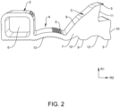
- Fig. 2 shows a schematic and perspective view of a sealing system 1 according to an embodiment of the present invention.
- the sealing system is shown as a profile body.
- the profile body extends in the profile body direction (in the Fig. 2 into the leaf plane).
- the Fig. 2 The sealing system shown is Fig. 1 .
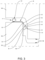
- Fig. 3 is a schematic cross-sectional view of the sealing system 1 of the previous embodiments in an installed operating state.
- a first pipe segment 14 upper segment
- a second pipe segment 15 lower segment
- An opposite surface of the two pipe segments 14, 15 is formed by a pipe segment surface 16.
- the pipe segment surface 16 is provided with several steps in the present embodiment.
- the sealing system 1 is arranged between the pipe segments 14, 15 so that the load distribution area 2 is in contact with both pipe segments 14, 15. Most of the load is carried by the load distribution area 2.
- the connecting area 4 is deflected around an edge of a step of the pipe segment surface 16 and then opens into the sealing area.
- the sealing area is therefore arranged rotated by essentially 90° relative to the load distribution area.
- the sealing area is pressed against the pipe segments 14 and 15 by an elastic deformation and thus seals a gap between the pipe segments 14, 15.
- the sliding layer 5 facilitates the assembly of the pipe segments. More precisely, the pipe segment 14 is Fig. 3 illustrated embodiment, it is placed from top to bottom onto the pipe segment 15. In this case, there may first be contact between the first pipe segment 14 and the sealing system 1 in an area between the connection area 4 and the sealing area 3.
- the sliding layer 5 is provided in this area.
- the sliding layer 5 is provided on both sides of the sealing system so that it can come into contact with both the first pipe segment 14 and the second pipe segment 15. Due to the lower friction in the area of the sliding layer, the first pipe segment 14 can slide easily onto the second pipe segment 15.
- the sealing system 1 does not hinder the pipe segments 14, 15 from being put together. In fact, the sealing system 1 promotes such a pushing together since this avoids friction between the first pipe segment 14 and the second pipe segment 15. If the two pipe segments 14, 15 are brought further together, the wedge-shaped section 7 of the sealing area 3 also comes into contact with the first pipe segment 14. In particular, the sealing area 3 contacts the first pipe segment 14 with the outer tip of the wedge-shaped section 7 (more precisely with the end of the wedge bevel 8). In this position, a sliding layer 5 is again provided so that this contact is also accompanied by a minimum of friction. This also ensures that the first rolling segment 14 and the second rolling segment 15. This makes it easy to bring the pipe segments 14, 15 together.
- the sealing system is installed by placing the sealing system all the way around the lower segment 15.
- the upper segment 14 is coupled or joined to the lower segment 15 by its own weight.
- a sealing effect is created by the sealing system 1.
- the sealing effect is provided by the wedge-shaped section 7.
- the load distribution area 2 distributes the load by equalizing it.
Landscapes
- Engineering & Computer Science (AREA)
- General Engineering & Computer Science (AREA)
- Mechanical Engineering (AREA)
- Health & Medical Sciences (AREA)
- Life Sciences & Earth Sciences (AREA)
- Hydrology & Water Resources (AREA)
- Public Health (AREA)
- Water Supply & Treatment (AREA)
- Joints With Sleeves (AREA)
Applications Claiming Priority (1)
| Application Number | Priority Date | Filing Date | Title |
|---|---|---|---|
| DE102023115765.5A DE102023115765A1 (de) | 2023-06-16 | 2023-06-16 | Dichtungssystem für Rohrsegmente und Verfahren zum Herstellen eines Dichtungssystems |
Publications (1)
| Publication Number | Publication Date |
|---|---|
| EP4477933A1 true EP4477933A1 (fr) | 2024-12-18 |
Family
ID=91581782
Family Applications (1)
| Application Number | Title | Priority Date | Filing Date |
|---|---|---|---|
| EP24182505.8A Pending EP4477933A1 (fr) | 2023-06-16 | 2024-06-17 | Système d'étanchéité pour segments de tuyau et procédé de fabrication d'un système d'étanchéité |
Country Status (2)
| Country | Link |
|---|---|
| EP (1) | EP4477933A1 (fr) |
| DE (1) | DE102023115765A1 (fr) |
Citations (3)
| Publication number | Priority date | Publication date | Assignee | Title |
|---|---|---|---|---|
| DE3826622A1 (de) * | 1988-08-05 | 1990-02-08 | Continental Ag | Dichtung fuer muffenrohrverbindungen |
| DE102004030528A1 (de) * | 2004-06-21 | 2006-01-26 | Pt-Poly-Tec Gmbh Vertrieb Und Herstellung Von Dichtsystemen | Dichtungs- und Lastausgleichssystem für Abwasserschächte und -kanäle oder ähnliche Bauwerke |
| EP1841999B1 (fr) * | 2005-01-27 | 2013-03-13 | Trelleborg Pipe Seals Lelystad BV | Bague d'etancheite |
-
2023
- 2023-06-16 DE DE102023115765.5A patent/DE102023115765A1/de active Pending
-
2024
- 2024-06-17 EP EP24182505.8A patent/EP4477933A1/fr active Pending
Patent Citations (3)
| Publication number | Priority date | Publication date | Assignee | Title |
|---|---|---|---|---|
| DE3826622A1 (de) * | 1988-08-05 | 1990-02-08 | Continental Ag | Dichtung fuer muffenrohrverbindungen |
| DE102004030528A1 (de) * | 2004-06-21 | 2006-01-26 | Pt-Poly-Tec Gmbh Vertrieb Und Herstellung Von Dichtsystemen | Dichtungs- und Lastausgleichssystem für Abwasserschächte und -kanäle oder ähnliche Bauwerke |
| EP1841999B1 (fr) * | 2005-01-27 | 2013-03-13 | Trelleborg Pipe Seals Lelystad BV | Bague d'etancheite |
Also Published As
| Publication number | Publication date |
|---|---|
| DE102023115765A1 (de) | 2024-12-19 |
Similar Documents
| Publication | Publication Date | Title |
|---|---|---|
| AT508701A4 (de) | Zahnradanordnung | |
| DE3414180A1 (de) | Dichtungseinrichtung fuer aneinanderstossende, zumindest etwa rohrfoermige bauteile, insbesondere fuer betonformteile | |
| DE102011080168A1 (de) | Konzept für einen geschlitzten Lagerkäfig | |
| WO2016193201A2 (fr) | Palier élastomère à coussinets | |
| DE102017212009A1 (de) | Zugentlastungstülle | |
| EP1811210A1 (fr) | Joint radial | |
| EP2764260B1 (fr) | Ensemble de raccordement pour un véhicule | |
| DE102018124406A1 (de) | Steckkupplung mit Toleranzausgleich | |
| EP0634532A2 (fr) | Arrangement pour joint d'étanchéité pour élément de construction | |
| EP2751361B1 (fr) | Butoir de porte et/ou de fenêtre | |
| EP4477933A1 (fr) | Système d'étanchéité pour segments de tuyau et procédé de fabrication d'un système d'étanchéité | |
| EP0348870A1 (fr) | Construction constituée par l'assemblage d'éléments préfabriqués en béton armé utilisant la technique du béton précontraint | |
| EP2724051B1 (fr) | Chaîne à rouleaux | |
| DE2809307A1 (de) | Steckmuffenverbindung von rohren und rohrelementen | |
| DE202013003947U1 (de) | Dichtring und Steckmuffenverbindung für den Kanalbau | |
| EP2086780A1 (fr) | Porte de véhicule avec un plan d'étanchéité et avec un élément d'étanchéité dont les extrémités se chevauchent | |
| DE102014217756A1 (de) | Verfahren zur Herstellung eines faserverstärkten Kunststoffteils und faserverstärktes Kunststoffteil | |
| EP1945985B1 (fr) | Systeme de liaison pour conduites, armatures ou unites | |
| EP2522791A1 (fr) | Profilé en caoutchouc destiné pour le raccordement de pièces de gouttières | |
| DE102018108402B4 (de) | Verbindungssteckteil für einen Felgenring, insbesondere für Fahrräder | |
| EP1003987B1 (fr) | Profile d'etancheite pour etancheifier deux corps cooperants, en particulier pour etancheifier des boitiers de lampes vis-a-vis de leurs vitres de fermeture | |
| DE102010042741B4 (de) | Scheibenwischvorrichtung aus einem Kunststoffverbund | |
| DE19522279A1 (de) | Bauteil für Steckmuffenverbindung | |
| EP0859183A1 (fr) | Anneau d'étanchéité pour anneaux de puits d'accès | |
| DE102013007297B4 (de) | Dichtring und Steckmuffenverbindung für den Kanalbau |
Legal Events
| Date | Code | Title | Description |
|---|---|---|---|
| PUAI | Public reference made under article 153(3) epc to a published international application that has entered the european phase |
Free format text: ORIGINAL CODE: 0009012 |
|
| STAA | Information on the status of an ep patent application or granted ep patent |
Free format text: STATUS: THE APPLICATION HAS BEEN PUBLISHED |
|
| AK | Designated contracting states |
Kind code of ref document: A1 Designated state(s): AL AT BE BG CH CY CZ DE DK EE ES FI FR GB GR HR HU IE IS IT LI LT LU LV MC ME MK MT NL NO PL PT RO RS SE SI SK SM TR |
|
| STAA | Information on the status of an ep patent application or granted ep patent |
Free format text: STATUS: REQUEST FOR EXAMINATION WAS MADE |
|
| 17P | Request for examination filed |
Effective date: 20250616 |
|
| STAA | Information on the status of an ep patent application or granted ep patent |
Free format text: STATUS: EXAMINATION IS IN PROGRESS |
|
| 17Q | First examination report despatched |
Effective date: 20251111 |