EP4477941A1 - Dispositif de rinçage, procédé de rinçage et système de rinçage - Google Patents
Dispositif de rinçage, procédé de rinçage et système de rinçage Download PDFInfo
- Publication number
- EP4477941A1 EP4477941A1 EP24162768.6A EP24162768A EP4477941A1 EP 4477941 A1 EP4477941 A1 EP 4477941A1 EP 24162768 A EP24162768 A EP 24162768A EP 4477941 A1 EP4477941 A1 EP 4477941A1
- Authority
- EP
- European Patent Office
- Prior art keywords
- flushing
- gas
- control section
- interface
- measuring
- Prior art date
- Legal status (The legal status is an assumption and is not a legal conclusion. Google has not performed a legal analysis and makes no representation as to the accuracy of the status listed.)
- Pending
Links
Images


Classifications
-
- F—MECHANICAL ENGINEERING; LIGHTING; HEATING; WEAPONS; BLASTING
- F17—STORING OR DISTRIBUTING GASES OR LIQUIDS
- F17D—PIPE-LINE SYSTEMS; PIPE-LINES
- F17D3/00—Arrangements for supervising or controlling working operations
- F17D3/10—Arrangements for supervising or controlling working operations for taking out the product in the line
-
- F—MECHANICAL ENGINEERING; LIGHTING; HEATING; WEAPONS; BLASTING
- F17—STORING OR DISTRIBUTING GASES OR LIQUIDS
- F17D—PIPE-LINE SYSTEMS; PIPE-LINES
- F17D1/00—Pipe-line systems
- F17D1/02—Pipe-line systems for gases or vapours
- F17D1/04—Pipe-line systems for gases or vapours for distribution of gas
-
- F—MECHANICAL ENGINEERING; LIGHTING; HEATING; WEAPONS; BLASTING
- F17—STORING OR DISTRIBUTING GASES OR LIQUIDS
- F17D—PIPE-LINE SYSTEMS; PIPE-LINES
- F17D3/00—Arrangements for supervising or controlling working operations
- F17D3/12—Arrangements for supervising or controlling working operations for injecting a composition into the line
-
- F—MECHANICAL ENGINEERING; LIGHTING; HEATING; WEAPONS; BLASTING
- F17—STORING OR DISTRIBUTING GASES OR LIQUIDS
- F17D—PIPE-LINE SYSTEMS; PIPE-LINES
- F17D3/00—Arrangements for supervising or controlling working operations
- F17D3/18—Arrangements for supervising or controlling working operations for measuring the quantity of conveyed product
Definitions
- the present invention relates to a flushing device for flushing a control section of a gas-carrying line.
- the invention further relates to a flushing method for flushing a control section of a gas-carrying line by means of a flushing device.
- the invention also relates to a flushing system with a flushing device and a gas-carrying line with a control section.
- the currently publicly known gas networks include a large number of devices that can be blocked for maintenance work, repairs and/or exchange with the gas network using fluid communication.
- the specifications for the operation of gas pressure control and measuring systems are subject to the DVGW regulations.
- the DVGW worksheets DVGW G491 and G495 contain specifications that reflect the state of the art and specify the necessary work steps.
- the gas at increased pressure in the closed parts of the system is discharged via a regulator into the downstream network during functional checks, maintenance work and/or other work.
- a rear shut-off valve is usually closed.
- the remaining gas is then usually released to the atmosphere via blow-out lines. The remaining gas escapes with Atmospheric pressure in the lines when opening filters, regulators or other fittings.
- the air in the system components is pushed into the atmosphere via the blow-out lines using the regular transport medium by opening a front shut-off element. In most cases, undetermined amounts of the medium escape again.
- the inventive solution helps to reduce emissions of flammable gases from the gas pipeline into the atmosphere, which currently mostly arise as a result of work such as functional checks and/or maintenance work on system components.
- the object is solved by a flushing device for flushing a control section of a gas-carrying line with the features of independent claim 1. Furthermore, the object is solved by a flushing method for flushing a control section of a gas-carrying line by a flushing device with the features of independent claim 11 and by a flushing system comprising a flushing device and a gas-carrying line with a control section with the features of independent claim 13. Further advantages and details of the invention emerge from the subclaims, the description and the drawings. Features that are described in connection with the flushing device according to the invention naturally also apply in connection with the flushing method according to the invention. the flushing system according to the invention and vice versa, so that with regard to the disclosure of the individual aspects of the invention, reference is always made to each other.
- the object is achieved by a flushing device for flushing a control section of a gas-carrying line, the flushing device comprising a supply interface for coupling the flushing device to the control section and for supplying flushing gas to the control section, a flushing gas interface for coupling a flushing gas source to the flushing device, wherein the supply interface and the flushing gas interface are connected to one another in a fluid-communicating manner, and a removal interface for coupling the flushing device to the control section and for removing gas from the control section, wherein the flushing device further comprises a measuring device downstream of the removal interface for measuring the gas from the control section.
- the gas-carrying line is preferably to be understood as a natural gas and/or hydrogen line.
- the purging device according to the invention preferably starts after the above-described work step of equalizing the pressure of the control section with respect to the gas-carrying line and/or in a control section with minimal technical residual pressure with respect to a downstream network and closing a rear blocking device, for example in the form of a shut-off valve, at the rear end of the control section.
- the purging device preferably enables the supply of a purging gas, preferably an inerting gas, for example nitrogen, into the control section in order to press the remaining gas in the control section out of the control section with a suitable overpressure from a purging gas source, for example a gas bottle, and/or by means of a conveying device of the purging gas source.
- a purging gas preferably an inerting gas, for example nitrogen
- the control section is also preferably blocked by a front blocking device in fluid communication with the gas-carrying line upstream of the control section. In other words, the control section is preferably blocked against the gas-carrying line by a front and a rear blocking device.
- the flushing device enables the supply interface and the removal interface to be coupled to the control section.
- the coupling of the supply interface and the removal interface to the control section is preferably designed to be detachable, in particular detachable without tools.
- the flushing device thus enables flushing gas to be supplied to the control section through the supply interface and gas and/or flushing gas to be removed from the control section through the removal interface.
- the flushing device enables the control section to be flushed with flushing gas and thus the gas to be removed from the control section.
- the extraction interface is preferably connected downstream to the gas-carrying line or a storage device for removing the gas from the control area, as described in detail in a later section.
- the flushing device is particularly advantageous because it comprises a measuring device downstream of the extraction interface for measuring the gas from the control section.
- the measuring device thus enables a progress check of the flushing process and/or a check of whether gas is still being pushed out of the control section by the supplied flushing gas.
- the flushing device records the content of combustible gas via at least one corresponding sensor of the measuring device.
- the mass flow can be detected by at least one corresponding sensor of the measuring device. This makes it possible to compare the volume pumped in the corresponding system section with the residual content of combustible gas in order to ensure, for example, verification of the measurement results.
- the flushing step can now be carried out and/or stopped manually or automatically by the flushing device and/or a user.
- the flushing device is preferably understood as a mobile flushing device.
- the flushing device is preferably understood as a portable flushing device and can thus be used advantageously, flexibly and quickly for a user on a large number of control sections of gas-carrying lines.
- the flushing device is designed within a housing and/or a case.
- a flushing device designed in this way is particularly advantageous since flushing of a control section of a gas-carrying line is made particularly easy, whereby the escape of gas from the control section into the environment is advantageously reduced or avoided.
- a flushing device in which the measuring device comprises a pressure measuring device for measuring at least one pressure within the measuring device, a concentration measuring device for measuring at least one gas concentration within the measuring device and/or in the surroundings of the measuring device and/or a mass flow measuring device for measuring at least one mass flow within the measuring device.
- the measuring device serves to check whether the control section is free of combustible gas and has therefore been filled exclusively or essentially exclusively with flushing gas.
- the wording "X or essentially X" is to be understood as a possible, small deviation, for example due to manufacturing tolerances, material and/or process properties, without changing the underlying, intended function of the feature.
- the measuring device comprises at least one pressure measuring device for measuring at least one pressure within the measuring device.
- the measuring device additionally or alternatively comprises at least one concentration measuring device for measuring at least one gas concentration within the measuring device and/or in the surroundings of the measuring device.
- the measurement of the gas concentration in the area surrounding the measuring device is preferably to be understood as a measurement of a possible leak in the flushing device and/or the gas-carrying line.
- the measuring device additionally or alternatively comprises at least one mass flow measuring device for measuring at least one mass flow within the measuring device.
- a measuring device designed in this way advantageously makes it possible, for example, to compare the volume conveyed from the corresponding control section with the residual content of combustible gas in order to ensure verification of the measurement results, for example.
- the measuring device preferably comprises at least one optical and/or acoustic output device for outputting data and/or warnings.
- a flushing device designed in this way is particularly advantageous due to the design of the measuring device, since flushing of a control section of a gas-carrying line and detection of the flushing are made particularly easy, whereby leakage of gas from the control section into the environment is advantageously reduced or avoided.
- a flushing device can be provided with the measuring device comprising an evaluation device for evaluating the recorded measured values and/or the measuring device comprising a transmitting and/or receiving device for transmitting and/or receiving the measured and/or evaluated measured values.
- the evaluation device according to the invention preferably enables a gas evaluation of the gas and/or the flushing gas from the control section.
- An evaluation preferably comprises an evaluation of the composition of the fluid, in particular a percentage composition.
- the measured and/or evaluated measured values are preferably sent to a server device and/or a storage device and/or receive default data and/or comparison data from these.
- the server device and/or storage device are preferably defined and/or designed separately from the flushing device or as part of the flushing device.
- a flushing device designed in this way is particularly advantageous due to the evaluation device and/or the transmitting and/or receiving device, since flushing of a control section of a gas-carrying line and the evaluation of the flushing are made particularly easy, whereby the escape of gas from the control section into the environment is advantageously reduced or avoided.
- the flushing gas interface can be coupled to a flushing gas source of the flushing device, in particular wherein the flushing gas source is designed as a mobile flushing gas source or as a stationary flushing gas source.
- the flushing gas source is designed as a component of the flushing device or as a separate flushing gas source.
- the flushing gas source is to be understood as a mobile flushing gas source, for example as a flushing gas tank, or as a stationary flushing gas source, for example as a flushing gas network.
- a mobile flushing gas source is particularly advantageous in combination with a mobile flushing device, since this enables a completely mobile and thus flexible use of the flushing device.
- a stationary flushing gas source is particularly advantageous since no volume limitation of the flushing gas source limits the process of flushing the control section.
- the flushing gas source enables a provision of purge gas for the purge device for purging a control section of a gas-carrying line.
- the purge gas is preferably conveyed by the pressure ratio of the purge gas source in relation to the control section.
- the purge gas source comprises a conveying device for conveying the purge gas into the control section.
- the purge gas is, as described above, preferably to be understood as an inerting gas, in particular as nitrogen. Nitrogen is particularly advantageous as a purge gas for purging a control section of a gas-carrying line, since nitrogen is inexpensive, heavier than natural gas and non-flammable.
- a purge device designed in this way is particularly advantageous due to the design of the purge gas source, since purging a control section of a gas-carrying line is made particularly easy, wherein the escape of gas from the control section into the environment is advantageously
- a flushing device can be provided in which the supply interface and/or the removal interface are designed for detachable coupling to the control section and/or in which the purge gas interface is designed for detachable coupling to the purge gas source.
- the coupling of the supply interface and/or the removal interface to the control section is preferably designed to be detachable, in particular detachable without tools.
- the flushing device thus enables the flushing device to be easily coupled to the control section and/or the gas-carrying line and then purge gas to be supplied to the control section through the supply interface and gas and/or purge gas to be removed from the control section through the removal interface.
- the flushing device enables easy assembly, flushing of the control section with purge gas and thus removal of the gas from the control section, and subsequent easy disassembly of the flushing device.
- the detachable couplings are designed, for example, as screw connections and/or plug-in couplings.
- the couplings preferably comprise flexible hoses and/or are preferably designed for pressures up to 70 bar or up to 100 bar.
- a flushing device designed in this way is particularly advantageous due to the design of the couplings, since assembly of the flushing device, disassembly of the flushing device and flushing of a control section of a gas-carrying line is made particularly easy, whereby the escape of gas from the control section into the environment is advantageously reduced or avoided.
- a flushing device can be provided with the supply interface, the removal interface and/or the flushing gas interface comprising at least one blocking device, wherein the at least one blocking device can be blocked in a fluid-tight manner.
- a blocking device is preferably to be understood as a valve, a shut-off valve, a manual blocking device and/or an automatic blocking device.
- the at least one blocking device preferably enables a fluid-communicating connection of the corresponding section to be blocked.
- a blocking device of the supply interface in combination with a blocking device of the removal interface preferably enables the control section to be blocked after the flushing process has been completed.
- a flushing device designed in this way is particularly advantageous due to the at least one blocking device, since flushing of a control section of a gas-carrying line is made particularly easy, wherein the escape of gas from the control section into the environment is advantageously reduced or avoided.
- the at least one blocking device advantageously enables the blocking of fluid-communicating connections and thus an advantageous environment for maintenance work, repairs and/or measurements on the control section and/or the gas-carrying line.
- a flushing device can be provided with a discharge interface downstream of the extraction interface and the measuring device for coupling the flushing device to the gas-carrying line, in particular downstream of the control section, and/or to a flushing storage device for discharging the extracted gas from the control section.
- the extraction interface is preferably connected downstream to the gas-carrying line, in particular downstream of the control section, or to a storage device for discharging the gas from the control area via the discharge interface.
- the gas extracted from the control section is therefore preferably fed to the downstream gas network or a flushing storage device.
- the flushing storage device is designed, for example, as a gas tank and serves to discharge the extracted gas from the control section.
- the discharge interface can preferably be coupled to the gas-carrying line and/or the flushing storage device in a detachable manner, in particular detachable without tools.
- One A flushing device designed in this way is particularly advantageous due to the discharge interface, since flushing of a control section of a gas-carrying line is made particularly easy, whereby a defined discharge of gas from the control section into the gas-carrying line and/or into the flushing storage device is made possible.
- a purging device can be provided with the extraction interface, the measuring device and/or the discharge interface comprising a filter device for filtering the extracted gas from the control section.
- the filter device according to the invention is preferably designed as a membrane for filtering the extracted gas from the control section. Additionally or alternatively, the filter device according to the invention is preferably designed as a membrane for separating gas and purge gas from the control section, in particular in order to reduce and/or avoid an unnecessary and/or technically unapproved proportion of purge gas in the downstream network and/or to reduce and/or avoid the release of combustible gas into the atmosphere.
- the extraction interface preferably comprises a blower device downstream of the filter device.
- the blower device preferably serves to discharge the gas in conjunction with a filter device, in particular a separation membrane for separating gas and purge gas, in order to release small amounts of mixed gas and/or separated purge gas into the atmosphere.
- the filter device preferably enables filtering and passage of the gas from the control section and blocking of the purge gas and/or other fluids.
- Such a filter device advantageously enables quality assurance of the gas in the gas-carrying line and avoidance of impurities in the gas.
- a purge device designed in this way is particularly advantageous due to the filter device, since purging of a control section of a gas-carrying line is made particularly easy, whereby a defined discharge of gas, in particular exclusively gas, from the control section is made possible, preferably into the gas-carrying line.
- the removal interface, the supply interface, the flushing gas interface, the measuring device and/or the discharge interface comprises a check valve device for blocking a fluid flow of the gas and/or the flushing gas in at least one direction.
- a check valve device enables a flow through the corresponding line section only on one side and consequently a blocking of a gas flow against the defined flow direction of the check valve device.
- the flushing device thus enables the flow direction of the gas and/or the flushing gas to be secured and/or an unwanted flow direction of the gas and/or the flushing gas to be prevented regardless of the respective pressure conditions.
- a check valve device of the flushing gas interface prevents a backflow of the flushing gas to the flushing gas source if the pressure in the flushing gas source falls to a level below the control section.
- a flushing device designed in this way is particularly advantageous due to the at least one check valve device, since flushing of a control section of a gas-carrying line is made particularly easy, whereby a defined guidance of gas and/or flushing gas is made possible.
- a flushing device in which the flushing device and/or the measuring device comprises an active and/or passive explosion protection device.
- An explosion protection device is preferably to be understood as protecting the flushing device against explosions and/or against explosion-promoting circumstances.
- a passive explosion protection device is to be understood as a casting compound at least in sections around the measuring device in order to avoid heat and/or spark sources in the vicinity of the gas-carrying line.
- An active explosion protection device is to be understood, for example, as a detection device for detecting gas leaks, heat developments and/or for detecting errors in the flushing device.
- a flushing device designed in this way is particularly advantageous due to the at least one explosion protection device, since flushing of a control section of a gas-carrying line is made particularly easy, whereby safe operation of the flushing device and/or the gas-carrying line is advantageously made possible.
- process steps described above and below can, unless explicitly stated otherwise, be carried out individually, together, once, multiple times, in parallel and/or one after the other in any order.
- a designation such as “first process step” and “second process step” does not imply any chronological order and/or prioritization.
- a preferred order of the process steps provides that the process steps are carried out in the order listed.
- the flushing device is preferably designed according to the first aspect, so that the described flushing method results in all the advantages that have already been described for the flushing device according to the first aspect of the invention.
- the flushing method preferably includes an evaluation of the measured gas.
- the flushing method preferably includes discharging the extracted gas from the control section via a discharge interface of the flushing device into the gas-carrying line, in particular downstream of the control section, and/or into a flushing storage device of the flushing device.
- the flushing method preferably includes blocking at least one blocking device of the flushing device, in particular the supply interface, the removal interface and/or the flushing gas interface. The blocking preferably takes place depending on the measured gas extracted from the control section.
- a flushing method designed in this way is particularly advantageous because flushing of a control section of a gas-carrying line is made particularly easy, whereby the escape of gas from the control section into the environment is advantageously reduced or avoided.
- a flushing method can provide that the supply of flushing gas into the control section and/or the removal of gas from the control section takes place depending on the measured gas removed from the control section.
- the flushing device preferably comprises locking devices and/or adjusting devices for the locking devices, wherein, for example, the adjusting devices open and/or close the locking devices depending on the measured gas removed from the control section.
- the flushing method preferably enables a comparison of the measured gas with at least one limit value, wherein the supply of flushing gas is stopped when the limit value is reached or undershot.
- the flushing method according to the invention thus advantageously enables the flushing to be checked and the flushing method to be stopped preferably automatically when only the limit value of the gas or no more gas is measured from the control section.
- a flushing method designed in this way is particularly advantageous because flushing of a control section of a gas-carrying line is made particularly simple and efficient, wherein the escape of gas from the control section into the environment is advantageously reduced or avoided.
- a flushing system comprising a flushing device and a gas-carrying line with a control section.
- the flushing device is designed according to the first aspect, so that the described flushing system offers all the advantages that have already been described for the flushing device according to the first aspect of the invention.
- the gas-carrying line preferably has corresponding counter-couplings for coupling to the supply interface, the removal interface and/or the discharge interface.
- a flushing system designed in this way is particularly advantageous because flushing of a control section of a gas-carrying line is made particularly easy, with the escape of gas from the control section into the environment being advantageously reduced or avoided.
- a flushing system can be provided in which the control section can be blocked in a fluid-tight manner against the gas-conducting line by at least one blocking device of the gas-conducting line, preferably by two blocking devices.
- at least one blocking device of the gas-conducting line preferably by two blocking devices.
- a flushing system designed in this way is particularly advantageous because flushing of a defined control section of a gas-carrying line is made particularly easy, whereby leakage of gas from the control section into the environment is advantageously reduced or avoided.
- the rinsing system is designed to carry out the rinsing method according to the second aspect, so that the described rinsing system offers all the advantages that have already been described for the rinsing method according to the second aspect of the invention.
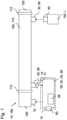
- Fig. 1 is shown schematically in a perspective view a flushing system 190 with a flushing device 10 and a gas-conducting line 100 with a control section 110.
- the flushing device 10 is designed for flushing the control section 110 of the gas-conducting line 100.
- the flushing device 10 comprises a supply interface 30 for coupling the flushing device 10 to the control section 110 and for supplying flushing gas I to the control section 110, a flushing gas interface 40 for coupling a flushing gas source 150 to the flushing device 10, wherein the supply interface 30 and the flushing gas interface 40 are connected to one another in a fluid-communicating manner and a Extraction interface 20 for coupling the purging device 10 to the control section 110 and for extracting gas G from the control section 110, wherein the purging device 10 further comprises a measuring device 50 downstream of the extraction interface 20 for measuring the gas G from the control section 110.
- the measuring device 50 comprises a pressure measuring device 52 for measuring a pressure within the measuring device 50, a concentration measuring device 54 for measuring a gas concentration within the measuring device 50 and in the surroundings of the measuring device 50 and a mass flow measuring device 56 for measuring a mass flow within the measuring device 50.
- the measuring device 50 comprises an evaluation device 58 for evaluating the recorded measured values and a transmitting and/or receiving device 60 for transmitting and/or receiving the measured and/or evaluated measured values.
- the purge gas interface 40 is coupled to a purge gas source 150 of the purge device 10, wherein the purge gas source 150 is designed as a mobile purge gas source 150.
- the supply interface 30 and the removal interface 20 are designed for detachable coupling to the control section 110.
- the purge gas interface 40 is further designed for detachable coupling to the purge gas source 150.
- the removal interface 20 comprises a locking device 14, wherein the locking device 14 can be locked in a fluid-tight manner.
- the purging device 10 comprises, downstream of the extraction interface 20 and the measuring device 50, a discharge interface 70 for coupling the purging device 10 to the gas-carrying line 100, here downstream of the control section 110, for discharging the extracted gas G from the control section 110.
- the extraction interface 20 comprises a filter device 80 for filtering the extracted gas G from the control section 110.
- the feed interface 30 comprises a check valve device 90 for blocking a fluid flow of the gas G and the purging gas I in one direction.
- the measuring device 50 comprises a passive explosion protection device 12 in the form of a cast casing.
- the control section 110 can be blocked in a fluid-tight manner against the gas-carrying line 100 by two blocking devices 112 of the gas-carrying line 100.
- FIG. 2 A further flushing system 190 with a flushing device 10 and a gas-carrying line 100 with a control section 110 is shown schematically in a perspective view.
- the flushing device 10 comprises downstream of the extraction interface 20 and the measuring device 50 a discharge interface 70 for coupling the flushing device 10 with a Flushing storage device 72 for discharging the extracted gas G from the control section 110.
- the flushing method 200 comprises, in a first method step, the coupling 202 of a supply interface 30 of the flushing device 10 to a control section 110 of the gas-carrying line 100.
- the flushing method 200 comprises, in a further method step, the coupling 204 of a purge gas interface 40 of the flushing device 10 to a purge gas source 150.
- the flushing method 200 comprises, in a further method step, the coupling 206 of a removal interface 20 of the flushing device 10 to a control section 110 of the gas-carrying line 100.
- the flushing method 200 comprises, in a further method step, the supply 208 of purge gas I into the control section 110 through the supply interface 30.
- the flushing method 200 comprises, in a further method step, the removal 210 of gas G from the control section 110 through the removal interface 20.
- the flushing method 200 comprises, in a further method step, the measuring 212 of the gas G extracted from the control section 110.
- the supply 208 of purge gas I into the control section 110 and the extraction 210 of gas G from the control section 110 takes place depending on the measured extracted gas G from the control section 110.
Landscapes
- Engineering & Computer Science (AREA)
- Mechanical Engineering (AREA)
- General Engineering & Computer Science (AREA)
- Sampling And Sample Adjustment (AREA)
Applications Claiming Priority (1)
| Application Number | Priority Date | Filing Date | Title |
|---|---|---|---|
| DE102023115549.0A DE102023115549A1 (de) | 2023-06-14 | 2023-06-14 | Spülvorrichtung, Spülverfahren und Spülsystem |
Publications (1)
| Publication Number | Publication Date |
|---|---|
| EP4477941A1 true EP4477941A1 (fr) | 2024-12-18 |
Family
ID=90364537
Family Applications (1)
| Application Number | Title | Priority Date | Filing Date |
|---|---|---|---|
| EP24162768.6A Pending EP4477941A1 (fr) | 2023-06-14 | 2024-03-11 | Dispositif de rinçage, procédé de rinçage et système de rinçage |
Country Status (2)
| Country | Link |
|---|---|
| EP (1) | EP4477941A1 (fr) |
| DE (1) | DE102023115549A1 (fr) |
Citations (4)
| Publication number | Priority date | Publication date | Assignee | Title |
|---|---|---|---|---|
| AT405442B (de) * | 1997-12-19 | 1999-08-25 | Wiener Stadtwerke | Verfahren und anordnung zur entfernung von brenngasen aus gasnetzen |
| WO2005026603A1 (fr) * | 2003-09-09 | 2005-03-24 | Tokyo Gas Company Limited | Procede et systeme de purge sous vide du gaz dans une tuyauterie ou un reservoir en service |
| ITBO20130346A1 (it) * | 2013-07-04 | 2015-01-05 | I S I F S R L | Sistema e metodo per eseguire in sicurezza interventi di installazione, riparazione, manutenzione sulle tubazioni delle reti gas |
| DE102015009013A1 (de) * | 2015-07-10 | 2017-01-12 | EEE Anlagenbau GmbH | Gasleitungsentleerungssystem und -verfahren |
-
2023
- 2023-06-14 DE DE102023115549.0A patent/DE102023115549A1/de active Pending
-
2024
- 2024-03-11 EP EP24162768.6A patent/EP4477941A1/fr active Pending
Patent Citations (4)
| Publication number | Priority date | Publication date | Assignee | Title |
|---|---|---|---|---|
| AT405442B (de) * | 1997-12-19 | 1999-08-25 | Wiener Stadtwerke | Verfahren und anordnung zur entfernung von brenngasen aus gasnetzen |
| WO2005026603A1 (fr) * | 2003-09-09 | 2005-03-24 | Tokyo Gas Company Limited | Procede et systeme de purge sous vide du gaz dans une tuyauterie ou un reservoir en service |
| ITBO20130346A1 (it) * | 2013-07-04 | 2015-01-05 | I S I F S R L | Sistema e metodo per eseguire in sicurezza interventi di installazione, riparazione, manutenzione sulle tubazioni delle reti gas |
| DE102015009013A1 (de) * | 2015-07-10 | 2017-01-12 | EEE Anlagenbau GmbH | Gasleitungsentleerungssystem und -verfahren |
Also Published As
| Publication number | Publication date |
|---|---|
| DE102023115549A1 (de) | 2024-12-19 |
Similar Documents
| Publication | Publication Date | Title |
|---|---|---|
| DE102004001916B4 (de) | Vorrichtung und Verfahren zur Probenahme | |
| DE3537940A1 (de) | Vorrichtung zur emissionsfreien probenahme von leicht verdampfbaren fluessigkeiten | |
| DE102015009013A1 (de) | Gasleitungsentleerungssystem und -verfahren | |
| EP2893247B1 (fr) | Procédé pour effectuer un essai de pression au niveau d'un réservoir et dispositif de remplissage de réservoir | |
| DE69819493T2 (de) | Verfahren zum prüfen von tanks | |
| EP4477941A1 (fr) | Dispositif de rinçage, procédé de rinçage et système de rinçage | |
| EP3646000B1 (fr) | Dispositif de test pour déterminer la charge en particules d'hydrogène sous haute pression | |
| DE3811041A1 (de) | Entnahmeventilkopf fuer behaelter | |
| DE102012011323A1 (de) | Befüllanlage, Befüllanordnung und Verfahren zum Befüllen eines Kältemitteltanks | |
| WO2023051945A1 (fr) | Procédé et système d'étalonnage de mesure de débit | |
| DE2901807A1 (de) | Vorrichtung zur ausbildung eines gegenstroms zur reinigung einer rohrleitung eines gasanalysators | |
| EP3256419B1 (fr) | Dispositif et procédé de transfert de fluides cryogéniques | |
| DE102018110567A1 (de) | Automatische Turboladerreinigungsvorrichtung | |
| DE9310532U1 (de) | Dampfeinblasvorrichtung | |
| EP3655747B1 (fr) | Dispositif de raccordement pour système de mesure des gaz d'échappement | |
| EP3377869B1 (fr) | Système d'encapsulage à surpression pour la protection anti-explosion et procédé de fonctionnement correspondant | |
| DE202014006478U1 (de) | Ventilsystem für Gasflaschenbündel | |
| EP4330536A1 (fr) | Procédé de test de l'intégrité d'un joint d'étanchéité et de composants d'un système de réservoir | |
| DE102019135704A1 (de) | Beprobungsvorrichtung zur sicheren Entnahme von Fluiden | |
| EP1186824B1 (fr) | Dispositif de connexion pour relier une conduite de fluide à un deuxième dispositif de connexion | |
| DE930710C (de) | Vorrichtung zum Sichtbarmachen von stroemender Luft | |
| DE2410300C3 (de) | Vorrichtung zur isokinetischen Entnahme von Gasproben aus einer Kanalströmung, insbesondere aus einer Reduktionsgase bei der Kohledruckvergasung führenden Rohrleitung | |
| EP1156248B1 (fr) | Agencement de soupape | |
| DE102022103583A1 (de) | Gasdetektionsanordnung für eine Brandschutzanlage, entsprechendes Verfahren zum Überwachen sowie Verwendung einer Gasdetektionsanordnung zum Überwachen einer Brandschutzanlage | |
| DE29910635U1 (de) | Prüfeinrichtung für einen Strömungsmelder |
Legal Events
| Date | Code | Title | Description |
|---|---|---|---|
| PUAI | Public reference made under article 153(3) epc to a published international application that has entered the european phase |
Free format text: ORIGINAL CODE: 0009012 |
|
| STAA | Information on the status of an ep patent application or granted ep patent |
Free format text: STATUS: THE APPLICATION HAS BEEN PUBLISHED |
|
| AK | Designated contracting states |
Kind code of ref document: A1 Designated state(s): AL AT BE BG CH CY CZ DE DK EE ES FI FR GB GR HR HU IE IS IT LI LT LU LV MC ME MK MT NL NO PL PT RO RS SE SI SK SM TR |
|
| STAA | Information on the status of an ep patent application or granted ep patent |
Free format text: STATUS: REQUEST FOR EXAMINATION WAS MADE |
|
| 17P | Request for examination filed |
Effective date: 20250313 |
|
| GRAP | Despatch of communication of intention to grant a patent |
Free format text: ORIGINAL CODE: EPIDOSNIGR1 |
|
| STAA | Information on the status of an ep patent application or granted ep patent |
Free format text: STATUS: GRANT OF PATENT IS INTENDED |
|
| RIC1 | Information provided on ipc code assigned before grant |
Ipc: F17D 3/10 20060101AFI20260116BHEP Ipc: F17D 3/12 20060101ALI20260116BHEP Ipc: F17D 3/18 20060101ALI20260116BHEP Ipc: F17D 1/04 20060101ALI20260116BHEP |
|
| INTG | Intention to grant announced |
Effective date: 20260130 |
|
| GRAS | Grant fee paid |
Free format text: ORIGINAL CODE: EPIDOSNIGR3 |
|
| GRAA | (expected) grant |
Free format text: ORIGINAL CODE: 0009210 |
|
| STAA | Information on the status of an ep patent application or granted ep patent |
Free format text: STATUS: THE PATENT HAS BEEN GRANTED |