EP4477960A1 - Appareil de chauffage - Google Patents
Appareil de chauffage Download PDFInfo
- Publication number
- EP4477960A1 EP4477960A1 EP24181293.2A EP24181293A EP4477960A1 EP 4477960 A1 EP4477960 A1 EP 4477960A1 EP 24181293 A EP24181293 A EP 24181293A EP 4477960 A1 EP4477960 A1 EP 4477960A1
- Authority
- EP
- European Patent Office
- Prior art keywords
- thermal device
- insulating body
- functional component
- housing
- designed
- Prior art date
- Legal status (The legal status is an assumption and is not a legal conclusion. Google has not performed a legal analysis and makes no representation as to the accuracy of the status listed.)
- Pending
Links
Images
Classifications
-
- F—MECHANICAL ENGINEERING; LIGHTING; HEATING; WEAPONS; BLASTING
- F24—HEATING; RANGES; VENTILATING
- F24D—DOMESTIC- OR SPACE-HEATING SYSTEMS, e.g. CENTRAL HEATING SYSTEMS; DOMESTIC HOT-WATER SUPPLY SYSTEMS; ELEMENTS OR COMPONENTS THEREFOR
- F24D19/00—Details
- F24D19/0097—Casings or frame structures for hydraulic components
-
- F—MECHANICAL ENGINEERING; LIGHTING; HEATING; WEAPONS; BLASTING
- F24—HEATING; RANGES; VENTILATING
- F24D—DOMESTIC- OR SPACE-HEATING SYSTEMS, e.g. CENTRAL HEATING SYSTEMS; DOMESTIC HOT-WATER SUPPLY SYSTEMS; ELEMENTS OR COMPONENTS THEREFOR
- F24D3/00—Hot-water central heating systems
- F24D3/10—Feed-line arrangements, e.g. providing for heat-accumulator tanks, expansion tanks ; Hydraulic components of a central heating system
- F24D3/1058—Feed-line arrangements, e.g. providing for heat-accumulator tanks, expansion tanks ; Hydraulic components of a central heating system disposition of pipes and pipe connections
- F24D3/1066—Distributors for heating liquids
-
- F—MECHANICAL ENGINEERING; LIGHTING; HEATING; WEAPONS; BLASTING
- F24—HEATING; RANGES; VENTILATING
- F24H—FLUID HEATERS, e.g. WATER OR AIR HEATERS, HAVING HEAT-GENERATING MEANS, e.g. HEAT PUMPS, IN GENERAL
- F24H1/00—Water heaters, e.g. boilers, continuous-flow heaters or water-storage heaters
- F24H1/18—Water-storage heaters
- F24H1/181—Construction of the tank
- F24H1/182—Insulation
-
- F—MECHANICAL ENGINEERING; LIGHTING; HEATING; WEAPONS; BLASTING
- F24—HEATING; RANGES; VENTILATING
- F24H—FLUID HEATERS, e.g. WATER OR AIR HEATERS, HAVING HEAT-GENERATING MEANS, e.g. HEAT PUMPS, IN GENERAL
- F24H9/00—Details
- F24H9/02—Casings; Cover lids; Ornamental panels
-
- F—MECHANICAL ENGINEERING; LIGHTING; HEATING; WEAPONS; BLASTING
- F24—HEATING; RANGES; VENTILATING
- F24H—FLUID HEATERS, e.g. WATER OR AIR HEATERS, HAVING HEAT-GENERATING MEANS, e.g. HEAT PUMPS, IN GENERAL
- F24H9/00—Details
- F24H9/06—Arrangement of mountings or supports
Definitions
- the invention relates to a thermal device according to the preamble of patent claim 1.
- a thermal device of the type mentioned above is known from the patent document DE 10 2018 132 504 A1
- This consists of a housing, an insulating body arranged in the housing, a receiving area formed on the insulating body and a functional component of the thermal device arranged in the receiving area and having a longitudinal axis.
- this device is a hot water tank with an insulating body made of particle foam (in particular EPP), to which a pipe, for example, is fixed as a functional component, in particular by clipping it in.
- EPP particle foam
- the invention is based on the object of improving a thermal device of the type mentioned at the beginning.
- the positioning of the functional component should be made easier during assembly and the position or location of the functional component should be secured in the long term during operation of the device.
- a first form-locking element and on the other hand a second form-locking element is provided on the functional component to fix it in the direction of its longitudinal axis and to match the first form-locking element.
- the solution according to the invention is characterized by the fact that, in addition to the already known radial fixation, an axial fixation of the functional component to the insulating body is now also provided in the receiving area. This facilitates assembly and also ensures in the long term that the functional component does not slip during operation of the thermal device. In addition, no additional fixation elements are necessary because these are contained in the insulating body.
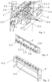
- the thermal device in particular a heating device, shown in the figures consists of a housing 1, an insulating body 2 arranged in the housing 1, a receiving area 2.1 formed on the insulating body 2 and a functional component 3 of the thermal device arranged in the receiving area 2.1 and having a longitudinal axis 3.1.
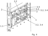
- Figure 1 and 4 the rear side of a new VITOCAL device from the applicant can be seen, more precisely, the rear side of an internal unit of a heat pump, with which the device faces a wall in the room in which it is installed.
- a hot water tank is preferably arranged in the preferably cuboid-shaped housing 1 (but not shown separately).
- the insulating body 2 is connected to the housing 1 in a form-fitting manner, preferably clipped onto the housing 1. Looking at it in a little more detail, it is preferably provided that the insulating body 2 is plugged on and then clamped in by a rear wall. This makes it possible to install the insulating body 2 without tools.
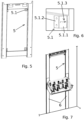
- the thermal device is not installed on a solid stone or concrete wall, but rather on a less stable plasterboard wall, for example is to be mounted, with reference to Figure 7
- at least one preferably telescopic or movable floor support 6 is assigned to the housing 1.
- the floor support 6 is designed to extend between the housing 1 and a building floor. It is very particularly preferred, as shown, that two strut-like floor supports 6 are arranged under the housing 1.
- the housing 1 has a support frame 1.2. It is further preferably provided that the support frame 1.2 of the housing 1 - preferably with the wall fastening device 5 - is mounted on the at least one floor support 6.
- the base support 6 is designed as a component that can be separated from the housing 1 without destruction.
- a first form-locking element 2.1.1 is provided on the receiving area 2.1 and on the other hand a second form-locking element 3.2 is provided on the functional component 3, which fits together with the first form-locking element 2.1.1 to fix it in the direction of its longitudinal axis 3.1.
- the longitudinal axis 3.1 of the functional component 3 is arranged or designed to run vertically in the receiving area 2.1.
- the functional component 3 is at least partially arranged between the said insulating body 2 and a counter-insulating body 4.
- This counter-insulating body 4 serves together with the insulating body 2 to create a liquid-tight closure for the piping and, if applicable, the cabling (see also further below) within the housing 1, which is particularly advantageous in order to significantly reduce the amount of condensate that accumulates within the housing, particularly during cooling.
- the insulating body 2 and/or the counter-insulating body 4 are formed from a foam material, preferably from a particle foam, particularly preferably from expanded polypropylene (EPP) or expanded polystyrene (EPS).
- EPP expanded polypropylene
- EPS expanded polystyrene
- the density of the foam material is preferably between 30 and 90 grams per liter, particularly preferably 60 grams per liter.
- At least three, preferably at least five, particularly preferably at least seven, receiving areas 2.1 for several functional components 3 are arranged, preferably in a horizontally running row, optionally on the insulating body 2 and/or on the counter-insulating body 4.
- the counter-insulating body 4 (with corresponding lateral overlapping areas) is designed to at least partially enclose the insulating body 2.
- a third form-locking element 4.3 is provided on the counter-insulating body 4 and on the other hand a fourth form-locking element 3.4 that matches the third form-locking element 4.3 is provided on the functional component 3.
- the functional component 3 is completely fixed between the insulating body 2 and the counter-insulating body 4.
- a fixing section at least partially enclosing the functional component 3 forms the second and fourth form-fitting elements 3.2, 3.4.
- the aforementioned axial fixation is thus realized or ensured not only between the functional component 3 and the insulating body 2, but also between the functional component 3 and the counter-insulating body 4.
- the functional component 3 is designed either as a tube or as a plug.
- the second form-locking element 3.2 and/or the fourth form-locking element 3.4 is designed as a compression of the pipe provided on the pipe, which could also be called a flanging. This compression then preferably forms the above-mentioned fixing section, which ensures the axial fixation of the functional component 3.
- the above mentioned plug is in Figure 4 It is used either to completely seal the receiving area 2.1 in a liquid-tight manner or to provide a liquid-tight passage for a cable or line of the thermal device (liquid-tight also includes preventing or preventing the passage of moist air).
- the plug is provided with a through-opening 3.3 for an additional functional component 3.5, in particular the cable in question.
- the through-opening 3.3 can preferably and optionally lie so tightly against the cable that it cannot slip axially, or the plug is directly connected to the cable in a materially bonded manner, ie the through-opening is created by separating the cable and the plug.
- either the second form-fitting element 3.2 facing the insulating body 2 and/or the fourth form-fitting element 3.4 facing the counter-insulating body 4 is formed by an edge of the plug.
- the plug can preferably, as in Figure 4 shown, have at least two form-locking elements 3.2 of different diameters in order to be able to be positioned in receiving areas 2.1 of different diameters (for thicker and thinner pipes).
- a contact area 3.6 shaped like half an inner cylinder is provided for the functional component 3 on the insulating body 2 and/or on the counter-insulating body 4, optionally above and/or below optionally the first and/or third form-locking element 2.1.1, 4.3.
- the first form-locking element 2.1.1 and/or the third form-locking element 4.3 is designed as a preferably semi-annular groove on the insulating body 2 or on the counter-insulating body 4.
- the The insulating body 2 and the counter-insulating body 4 are designed to accommodate the functional component 3 and/or the additional functional component 3.5 (for example a cable with a plug-like injection molding) between them in a liquid-tight manner.
- the functional component 3 and/or the additional functional component 3.5 for example a cable with a plug-like injection molding
- connecting elements 2.2, 4.2 which match one another and are designed for preferably horizontal mutual attachment to one another are provided on the insulating body 2 and the counter-insulating body 4.
- At least one handle element 4.1 is provided on the counter-insulating body 4.
- the handle element 4.1 is particularly preferably designed as a projection arranged in a recess on the counter-insulating body 4.
- a cable duct 1.1 preferably made of a rubber-elastic material, in particular ethylene-propylene-diene rubber (EPDM), is also preferably provided on the housing 1.
- EPDM ethylene-propylene-diene rubber
- the assembly of the thermal device according to the invention is carried out as follows: First, the insulating body 2 is fixed to the housing 1 by snapping it into place. The pipes are then guided through the receiving areas 2.1 and are preferably and optionally fixed axially there with the compressions (or preferably flanges). The lines or cables are sealed in the same way with the plugs. Unused receiving areas 2.1 can also be sealed with a plug. Finally, the counter-insulating body 4 is pressed onto the insulating body 2 using the handle element 4.1, of which two are preferably provided, so that the connecting elements 2.2 and 4.2 are connected to one another in a form-fitting manner and thus ensure a liquid-tight seal. This means that the entire system can be assembled without tools. No screw connections or similar are necessary; fastening is carried out exclusively using form-fitting geometries.
- the thermal device In order to be able to attach the thermal device to uneven walls in the simplest possible way, it is also necessary to refer to the Figures 5 and 6 preferably on the housing 1 (here - because it is easily conceivable - not shown separately) preferably arranged on a support frame 1.2 of the housing 1 (see Figure 1 ) and preferably at least one, preferably (as shown here) at least four wall anchors 5.1 having wall fastening device 5 are provided.
- the wall anchor 5.1 has a first fastening section 5.1.1 for fastening to the housing 1 and a second fastening section 5.1.2 for fastening to a building wall.
- the wall anchor 5.1 is preferably designed as an angled sheet metal, wherein the first fastening section 5.1.1 preferably forms a first sheet metal section and the second fastening section 5.1.2 forms a second sheet metal section angled to the first sheet metal section.
- the wall anchor 5.1 has a tolerance compensation device 5.1.3.
- the tolerance compensation device 5.1.3 is designed as an adjustable and fixable slotted screw connection, preferably provided on the first fastening section 5.1.1.
Landscapes
- Engineering & Computer Science (AREA)
- Physics & Mathematics (AREA)
- Thermal Sciences (AREA)
- Chemical & Material Sciences (AREA)
- Combustion & Propulsion (AREA)
- Mechanical Engineering (AREA)
- General Engineering & Computer Science (AREA)
- Thermal Insulation (AREA)
Applications Claiming Priority (1)
| Application Number | Priority Date | Filing Date | Title |
|---|---|---|---|
| DE102023115377.3A DE102023115377A1 (de) | 2023-06-13 | 2023-06-13 | Wärmetechnisches Gerät |
Publications (1)
| Publication Number | Publication Date |
|---|---|
| EP4477960A1 true EP4477960A1 (fr) | 2024-12-18 |
Family
ID=91481822
Family Applications (1)
| Application Number | Title | Priority Date | Filing Date |
|---|---|---|---|
| EP24181293.2A Pending EP4477960A1 (fr) | 2023-06-13 | 2024-06-11 | Appareil de chauffage |
Country Status (2)
| Country | Link |
|---|---|
| EP (1) | EP4477960A1 (fr) |
| DE (1) | DE102023115377A1 (fr) |
Citations (7)
| Publication number | Priority date | Publication date | Assignee | Title |
|---|---|---|---|---|
| DE1917009U (de) * | 1965-04-01 | 1965-06-03 | Wolfgang Prinz | Heizkoerper-konsole. |
| EP0507104B1 (fr) * | 1991-03-19 | 1994-06-08 | WILO GmbH | Appareil pour alimenter une chauffage pour le sol |
| EP0597342B1 (fr) * | 1992-11-10 | 1996-09-25 | VIESSMANN WERKE GmbH & CO. | Chaudière |
| EP2778544B1 (fr) * | 2013-03-11 | 2017-10-04 | Gebr. Tuxhorn GmbH & Co. KG | Groupe de robinetterie |
| DE102018132504A1 (de) | 2018-12-17 | 2020-06-18 | Stiebel Eltron Gmbh & Co. Kg | Warmwasserspeicher und zugehöriges Montageverfahren |
| DE102021118041A1 (de) * | 2021-07-13 | 2023-01-19 | Stiebel Eltron Gmbh & Co. Kg | Haustechnikgerät |
| DE102021118038A1 (de) * | 2021-07-13 | 2023-02-09 | Stiebel Eltron Gmbh & Co. Kg | Haustechnikgerät und Bedienelement für ein Haustechnikgerät |
Family Cites Families (1)
| Publication number | Priority date | Publication date | Assignee | Title |
|---|---|---|---|---|
| DE202004012263U1 (de) * | 2004-08-05 | 2004-10-07 | Stiebel Eltron Gmbh & Co. Kg | Durchlauferhitzer |
-
2023
- 2023-06-13 DE DE102023115377.3A patent/DE102023115377A1/de active Pending
-
2024
- 2024-06-11 EP EP24181293.2A patent/EP4477960A1/fr active Pending
Patent Citations (7)
| Publication number | Priority date | Publication date | Assignee | Title |
|---|---|---|---|---|
| DE1917009U (de) * | 1965-04-01 | 1965-06-03 | Wolfgang Prinz | Heizkoerper-konsole. |
| EP0507104B1 (fr) * | 1991-03-19 | 1994-06-08 | WILO GmbH | Appareil pour alimenter une chauffage pour le sol |
| EP0597342B1 (fr) * | 1992-11-10 | 1996-09-25 | VIESSMANN WERKE GmbH & CO. | Chaudière |
| EP2778544B1 (fr) * | 2013-03-11 | 2017-10-04 | Gebr. Tuxhorn GmbH & Co. KG | Groupe de robinetterie |
| DE102018132504A1 (de) | 2018-12-17 | 2020-06-18 | Stiebel Eltron Gmbh & Co. Kg | Warmwasserspeicher und zugehöriges Montageverfahren |
| DE102021118041A1 (de) * | 2021-07-13 | 2023-01-19 | Stiebel Eltron Gmbh & Co. Kg | Haustechnikgerät |
| DE102021118038A1 (de) * | 2021-07-13 | 2023-02-09 | Stiebel Eltron Gmbh & Co. Kg | Haustechnikgerät und Bedienelement für ein Haustechnikgerät |
Also Published As
| Publication number | Publication date |
|---|---|
| DE102023115377A1 (de) | 2024-12-19 |
Similar Documents
| Publication | Publication Date | Title |
|---|---|---|
| EP3384567B1 (fr) | Châssis pour armoire électrique | |
| DE69816934T2 (de) | Kabeldurchführung | |
| WO2019214894A1 (fr) | Traversée de paroi | |
| EP0662547A1 (fr) | Elément de sol pour chauffage et refroidissement par le sol | |
| EP3433912B1 (fr) | Un support de pièce plate pour fixer une pièce plate à un cadre d'une armoire électrique et armoire électrique correspondante | |
| DE29719639U1 (de) | Vorrichtung zum Beheizen von Innenräumen, insbesondere von Kraftfahrzeugen | |
| DE4137038C1 (en) | Radiator case for front body of motor vehicle - has distance pieces, one elastic, to clamp flat tube heat exchanger between frame and collectors | |
| DE102010043165B4 (de) | Aggregatlager mit integrierten Wegbegrenzern und Verfahren zur Fertigung | |
| DE3000196A1 (de) | Klemmanordnung | |
| EP1516402A1 (fr) | Attache de cable | |
| EP0939980A1 (fr) | Baie comportant un cadre inferieur et un cadre superieur constitues d'un profile continu | |
| EP4477960A1 (fr) | Appareil de chauffage | |
| EP3591268A1 (fr) | Connecteur de conduite de fluide pourvu de pièce d'insertion fixe destinée à l'étranglement | |
| DE60100008T2 (de) | Kabelrinnenabschnitte und daraus hergestellte Kabelrinne durch Verbinbung von mindestens zwei Abschnitten und deren Herstellungsverfahren | |
| DE29808031U1 (de) | Paneel- bzw. Flachheizkörper | |
| DE102020114176A1 (de) | Kühleinrichtung für eine Kraftfahrzeugbatterie | |
| DE3832399A1 (de) | Rohrhalter und verfahren zur rohrmontage mittels eines rohrhalters | |
| DE102022125081B3 (de) | Bodenstütze eines Kabeltragsystems | |
| EP4249782B1 (fr) | Pièce d'insonorisation en matériau isolant pour collier de serrage et collier de serrage comprenant une telle pièce d'insonorisation | |
| DE69905814T2 (de) | Verstellbare Eck-Verbindung für Kabelkanäle | |
| DE3301229A1 (de) | Breitbandschelle zum abgedichteten verbinden von glattzylindrischen rohrenden, insbesondere von abwasserrohren mittels eines dichtungselements | |
| DE202019102525U1 (de) | Montagerahmen zum Montieren eines Luftauslasses eines Dunstabzugsystems in einer Öffnung und eine entsprechende Anordnung | |
| EP1652704B1 (fr) | Ensemble de chauffage électrique, notamment pour véhicule automobile | |
| EP1565695B1 (fr) | Condensateur | |
| DE69804703T2 (de) | Kanalverbindung |
Legal Events
| Date | Code | Title | Description |
|---|---|---|---|
| PUAI | Public reference made under article 153(3) epc to a published international application that has entered the european phase |
Free format text: ORIGINAL CODE: 0009012 |
|
| STAA | Information on the status of an ep patent application or granted ep patent |
Free format text: STATUS: THE APPLICATION HAS BEEN PUBLISHED |
|
| AK | Designated contracting states |
Kind code of ref document: A1 Designated state(s): AL AT BE BG CH CY CZ DE DK EE ES FI FR GB GR HR HU IE IS IT LI LT LU LV MC ME MK MT NL NO PL PT RO RS SE SI SK SM TR |
|
| RAP1 | Party data changed (applicant data changed or rights of an application transferred) |
Owner name: VIESSMANN HOLDING INTERNATIONAL GMBH |
|
| STAA | Information on the status of an ep patent application or granted ep patent |
Free format text: STATUS: REQUEST FOR EXAMINATION WAS MADE |
|
| 17P | Request for examination filed |
Effective date: 20250527 |