EP4477978A1 - Réfrigérateur et procédé de commande associé - Google Patents
Réfrigérateur et procédé de commande associé Download PDFInfo
- Publication number
- EP4477978A1 EP4477978A1 EP23852868.1A EP23852868A EP4477978A1 EP 4477978 A1 EP4477978 A1 EP 4477978A1 EP 23852868 A EP23852868 A EP 23852868A EP 4477978 A1 EP4477978 A1 EP 4477978A1
- Authority
- EP
- European Patent Office
- Prior art keywords
- push rod
- door
- motor
- waiting time
- switch
- Prior art date
- Legal status (The legal status is an assumption and is not a legal conclusion. Google has not performed a legal analysis and makes no representation as to the accuracy of the status listed.)
- Pending
Links
Images









Classifications
-
- F—MECHANICAL ENGINEERING; LIGHTING; HEATING; WEAPONS; BLASTING
- F25—REFRIGERATION OR COOLING; COMBINED HEATING AND REFRIGERATION SYSTEMS; HEAT PUMP SYSTEMS; MANUFACTURE OR STORAGE OF ICE; LIQUEFACTION SOLIDIFICATION OF GASES
- F25D—REFRIGERATORS; COLD ROOMS; ICE-BOXES; COOLING OR FREEZING APPARATUS NOT OTHERWISE PROVIDED FOR
- F25D23/00—General constructional features
- F25D23/02—Doors; Covers
- F25D23/028—Details
-
- E—FIXED CONSTRUCTIONS
- E05—LOCKS; KEYS; WINDOW OR DOOR FITTINGS; SAFES
- E05F—DEVICES FOR MOVING WINGS INTO OPEN OR CLOSED POSITION; CHECKS FOR WINGS; WING FITTINGS NOT OTHERWISE PROVIDED FOR, CONCERNED WITH THE FUNCTIONING OF THE WING
- E05F15/00—Power-operated mechanisms for wings
- E05F15/60—Power-operated mechanisms for wings using electrical actuators
- E05F15/603—Power-operated mechanisms for wings using electrical actuators using rotary electromotors
- E05F15/611—Power-operated mechanisms for wings using electrical actuators using rotary electromotors for swinging wings
- E05F15/614—Power-operated mechanisms for wings using electrical actuators using rotary electromotors for swinging wings operated by meshing gear wheels, one of which being mounted at the wing pivot axis; operated by a motor acting directly on the wing pivot axis
-
- E—FIXED CONSTRUCTIONS
- E05—LOCKS; KEYS; WINDOW OR DOOR FITTINGS; SAFES
- E05F—DEVICES FOR MOVING WINGS INTO OPEN OR CLOSED POSITION; CHECKS FOR WINGS; WING FITTINGS NOT OTHERWISE PROVIDED FOR, CONCERNED WITH THE FUNCTIONING OF THE WING
- E05F15/00—Power-operated mechanisms for wings
- E05F15/60—Power-operated mechanisms for wings using electrical actuators
- E05F15/603—Power-operated mechanisms for wings using electrical actuators using rotary electromotors
- E05F15/611—Power-operated mechanisms for wings using electrical actuators using rotary electromotors for swinging wings
- E05F15/616—Power-operated mechanisms for wings using electrical actuators using rotary electromotors for swinging wings operated by push-pull mechanisms
-
- E—FIXED CONSTRUCTIONS
- E05—LOCKS; KEYS; WINDOW OR DOOR FITTINGS; SAFES
- E05F—DEVICES FOR MOVING WINGS INTO OPEN OR CLOSED POSITION; CHECKS FOR WINGS; WING FITTINGS NOT OTHERWISE PROVIDED FOR, CONCERNED WITH THE FUNCTIONING OF THE WING
- E05F15/00—Power-operated mechanisms for wings
- E05F15/60—Power-operated mechanisms for wings using electrical actuators
- E05F15/603—Power-operated mechanisms for wings using electrical actuators using rotary electromotors
- E05F15/611—Power-operated mechanisms for wings using electrical actuators using rotary electromotors for swinging wings
- E05F15/616—Power-operated mechanisms for wings using electrical actuators using rotary electromotors for swinging wings operated by push-pull mechanisms
- E05F15/619—Power-operated mechanisms for wings using electrical actuators using rotary electromotors for swinging wings operated by push-pull mechanisms using flexible or rigid rack-and-pinion arrangements
-
- E—FIXED CONSTRUCTIONS
- E05—LOCKS; KEYS; WINDOW OR DOOR FITTINGS; SAFES
- E05F—DEVICES FOR MOVING WINGS INTO OPEN OR CLOSED POSITION; CHECKS FOR WINGS; WING FITTINGS NOT OTHERWISE PROVIDED FOR, CONCERNED WITH THE FUNCTIONING OF THE WING
- E05F15/00—Power-operated mechanisms for wings
- E05F15/70—Power-operated mechanisms for wings with automatic actuation
- E05F15/73—Power-operated mechanisms for wings with automatic actuation responsive to movement or presence of persons or objects
- E05F15/75—Power-operated mechanisms for wings with automatic actuation responsive to movement or presence of persons or objects responsive to the weight or other physical contact of a person or object
-
- F—MECHANICAL ENGINEERING; LIGHTING; HEATING; WEAPONS; BLASTING
- F25—REFRIGERATION OR COOLING; COMBINED HEATING AND REFRIGERATION SYSTEMS; HEAT PUMP SYSTEMS; MANUFACTURE OR STORAGE OF ICE; LIQUEFACTION SOLIDIFICATION OF GASES
- F25D—REFRIGERATORS; COLD ROOMS; ICE-BOXES; COOLING OR FREEZING APPARATUS NOT OTHERWISE PROVIDED FOR
- F25D23/00—General constructional features
- F25D23/02—Doors; Covers
-
- F—MECHANICAL ENGINEERING; LIGHTING; HEATING; WEAPONS; BLASTING
- F25—REFRIGERATION OR COOLING; COMBINED HEATING AND REFRIGERATION SYSTEMS; HEAT PUMP SYSTEMS; MANUFACTURE OR STORAGE OF ICE; LIQUEFACTION SOLIDIFICATION OF GASES
- F25D—REFRIGERATORS; COLD ROOMS; ICE-BOXES; COOLING OR FREEZING APPARATUS NOT OTHERWISE PROVIDED FOR
- F25D29/00—Arrangement or mounting of control or safety devices
-
- E—FIXED CONSTRUCTIONS
- E05—LOCKS; KEYS; WINDOW OR DOOR FITTINGS; SAFES
- E05F—DEVICES FOR MOVING WINGS INTO OPEN OR CLOSED POSITION; CHECKS FOR WINGS; WING FITTINGS NOT OTHERWISE PROVIDED FOR, CONCERNED WITH THE FUNCTIONING OF THE WING
- E05F17/00—Special devices for shifting a plurality of wings operated simultaneously
- E05F17/004—Special devices for shifting a plurality of wings operated simultaneously for wings which abut when closed
-
- E—FIXED CONSTRUCTIONS
- E05—LOCKS; KEYS; WINDOW OR DOOR FITTINGS; SAFES
- E05Y—INDEXING SCHEME ASSOCIATED WITH SUBCLASSES E05D AND E05F, RELATING TO CONSTRUCTION ELEMENTS, ELECTRIC CONTROL, POWER SUPPLY, POWER SIGNAL OR TRANSMISSION, USER INTERFACES, MOUNTING OR COUPLING, DETAILS, ACCESSORIES, AUXILIARY OPERATIONS NOT OTHERWISE PROVIDED FOR, APPLICATION THEREOF
- E05Y2201/00—Constructional elements; Accessories therefor
- E05Y2201/40—Motors; Magnets; Springs; Weights; Accessories therefor
- E05Y2201/404—Function thereof
- E05Y2201/422—Function thereof for opening
- E05Y2201/426—Function thereof for opening for the initial opening movement
-
- E—FIXED CONSTRUCTIONS
- E05—LOCKS; KEYS; WINDOW OR DOOR FITTINGS; SAFES
- E05Y—INDEXING SCHEME ASSOCIATED WITH SUBCLASSES E05D AND E05F, RELATING TO CONSTRUCTION ELEMENTS, ELECTRIC CONTROL, POWER SUPPLY, POWER SIGNAL OR TRANSMISSION, USER INTERFACES, MOUNTING OR COUPLING, DETAILS, ACCESSORIES, AUXILIARY OPERATIONS NOT OTHERWISE PROVIDED FOR, APPLICATION THEREOF
- E05Y2201/00—Constructional elements; Accessories therefor
- E05Y2201/60—Suspension or transmission members; Accessories therefor
- E05Y2201/622—Suspension or transmission members elements
- E05Y2201/686—Rods, links
-
- E—FIXED CONSTRUCTIONS
- E05—LOCKS; KEYS; WINDOW OR DOOR FITTINGS; SAFES
- E05Y—INDEXING SCHEME ASSOCIATED WITH SUBCLASSES E05D AND E05F, RELATING TO CONSTRUCTION ELEMENTS, ELECTRIC CONTROL, POWER SUPPLY, POWER SIGNAL OR TRANSMISSION, USER INTERFACES, MOUNTING OR COUPLING, DETAILS, ACCESSORIES, AUXILIARY OPERATIONS NOT OTHERWISE PROVIDED FOR, APPLICATION THEREOF
- E05Y2201/00—Constructional elements; Accessories therefor
- E05Y2201/60—Suspension or transmission members; Accessories therefor
- E05Y2201/622—Suspension or transmission members elements
- E05Y2201/71—Toothed gearing
- E05Y2201/722—Racks
-
- E—FIXED CONSTRUCTIONS
- E05—LOCKS; KEYS; WINDOW OR DOOR FITTINGS; SAFES
- E05Y—INDEXING SCHEME ASSOCIATED WITH SUBCLASSES E05D AND E05F, RELATING TO CONSTRUCTION ELEMENTS, ELECTRIC CONTROL, POWER SUPPLY, POWER SIGNAL OR TRANSMISSION, USER INTERFACES, MOUNTING OR COUPLING, DETAILS, ACCESSORIES, AUXILIARY OPERATIONS NOT OTHERWISE PROVIDED FOR, APPLICATION THEREOF
- E05Y2900/00—Application of doors, windows, wings or fittings thereof
- E05Y2900/30—Application of doors, windows, wings or fittings thereof for domestic appliances
- E05Y2900/31—Application of doors, windows, wings or fittings thereof for domestic appliances for refrigerators
-
- F—MECHANICAL ENGINEERING; LIGHTING; HEATING; WEAPONS; BLASTING
- F25—REFRIGERATION OR COOLING; COMBINED HEATING AND REFRIGERATION SYSTEMS; HEAT PUMP SYSTEMS; MANUFACTURE OR STORAGE OF ICE; LIQUEFACTION SOLIDIFICATION OF GASES
- F25D—REFRIGERATORS; COLD ROOMS; ICE-BOXES; COOLING OR FREEZING APPARATUS NOT OTHERWISE PROVIDED FOR
- F25D2323/00—General constructional features not provided for in other groups of this subclass
- F25D2323/02—Details of doors or covers not otherwise covered
- F25D2323/021—French doors
-
- F—MECHANICAL ENGINEERING; LIGHTING; HEATING; WEAPONS; BLASTING
- F25—REFRIGERATION OR COOLING; COMBINED HEATING AND REFRIGERATION SYSTEMS; HEAT PUMP SYSTEMS; MANUFACTURE OR STORAGE OF ICE; LIQUEFACTION SOLIDIFICATION OF GASES
- F25D—REFRIGERATORS; COLD ROOMS; ICE-BOXES; COOLING OR FREEZING APPARATUS NOT OTHERWISE PROVIDED FOR
- F25D2323/00—General constructional features not provided for in other groups of this subclass
- F25D2323/02—Details of doors or covers not otherwise covered
- F25D2323/024—Door hinges
-
- F—MECHANICAL ENGINEERING; LIGHTING; HEATING; WEAPONS; BLASTING
- F25—REFRIGERATION OR COOLING; COMBINED HEATING AND REFRIGERATION SYSTEMS; HEAT PUMP SYSTEMS; MANUFACTURE OR STORAGE OF ICE; LIQUEFACTION SOLIDIFICATION OF GASES
- F25D—REFRIGERATORS; COLD ROOMS; ICE-BOXES; COOLING OR FREEZING APPARATUS NOT OTHERWISE PROVIDED FOR
- F25D2700/00—Means for sensing or measuring; Sensors therefor
- F25D2700/02—Sensors detecting door opening
Definitions
- the disclosure relates to a refrigerator and a control method thereof, and more particularly, to a refrigerator including a door opening device configured to open a door and a control method thereof.
- a refrigerator is a home appliance that keeps food fresh by including a main body including a storage compartment, a cold air supply device configured to supply cold air to the storage compartment, and a door configured to open and close the storage compartment.
- the refrigerator may be provided with a door opening device that helps to open the door comfortably.
- a door opening device that helps to open the door comfortably.
- air inside the storage compartment may be cooled, and a temperature difference between the inside and outside of the storage compartment may occur. Accordingly, a pressure difference between the inside and outside of the storage compartment may occur.
- the door is in close contact with the main body through a gasket containing a magnet. Therefore, when opening the door, a lot of force may be required at an initial stage of opening.
- the door opening device may push a rear surface of the door, thereby opening the door at a predetermined angle. Accordingly, the user can open the door with little force.
- a refrigerator including a door opening device capable of opening a plurality of doors arranged in left and right directions, and a control method thereof.
- a control method of a refrigerator may include a main body, a first door, a second door, a door opening device, a first switch, a second switch, and a speaker, the main body including a storage compartment, the first door and the second door being rotatably coupled to the main body and being disposed in left and right directions so as to open and close the storage compartment, the door opening device including a motor configured to allow a first push rod and a second push rod to be interlocked with each other and moved in opposite directions, the first push rod being configured to press the first door, the second push rod being configured to press the second door, the first switch and the second switch being configured to receive a user input, the speaker being configured to generate a notification sound, may include, in response to receiving a user input from the first switch, driving the motor in a forward direction until the first push rod reaches a maximum forward position of the first push rod from a neutral position of the first push rod, performing at least one of stopping the motor or driving the motor in a
- the predetermined waiting time may be initially set as a first reference waiting time.
- the predetermined waiting time may be changed from the first reference waiting time to a second reference waiting time less than the first reference waiting time.
- the second reference driving speed may be greater than the first reference driving speed.
- the performing of the at least one of stopping the motor or driving the motor in the reverse direction at the first reference driving speed before the predetermined waiting time elapses from when the first push rod reaches the maximum forward position of the first push rod may include stopping the motor throughout the predetermined waiting time from when the first push rod reaches the maximum forward position of the first push rod.
- the performing of the at least one of stopping the motor or driving the motor in the reverse direction at the first reference driving speed before the predetermined waiting time elapses from when the first push rod reaches the maximum forward position of the first push rod may include driving the motor in the reverse direction at the first reference driving speed throughout the predetermined waiting time from when the first push rod reaches the maximum forward position of the first push rod.
- the performing of the at least one of stopping the motor or driving the motor in the reverse direction at the first reference driving speed before the predetermined waiting time elapses from when the first push rod reaches the maximum forward position of the first push rod may include stopping the motor for the second reference waiting time from when the first push rod reaches the maximum forward position of the first push rod, and driving the motor in the reverse direction at the first reference speed for a third reference waiting time, which is a difference between the first reference waiting time and the second reference waiting time, after the second reference waiting time elapses from when the first push rod reaches the maximum forward position of the first push rod.
- the first reference waiting time and the second reference waiting time may be set by a user.
- the control method may further include, in response to receiving a user input from the second switch while the motor is driven in the forward direction until the first push rod reaches the maximum forward position of the first push rod from the neutral position of the first push rod, driving the motor in the reverse direction at the second reference driving speed until the second push rod reaches a maximum forward position of the second push rod from a neutral position of the second push rod.
- Driving the motor in the reverse direction at the second reference driving speed until the first push rod returns to the neutral position of the first push rod, and driving the motor in the reverse direction at the second reference driving speed until the second push rod reaches the maximum forward position of the second push rod from the neutral position of the second push rod may be continuously performed.
- the control method may further include changing the predetermined waiting time in response to receiving a user input from the second switch while the at least one of stopping the motor or driving the motor in the reverse direction at the first reference driving speed is performed before the predetermined waiting time elapses from when the first push rod reaches the maximum forward position of the first push rod.
- the control method may further include outputting a notification sound through the speaker in response to receiving a user input from the second switch while the motor is driven in the forward direction until the first push rod reaches the maximum forward position of the first push rod from the neutral position of the first push rod.
- the control method may further include outputting a notification sound through the speaker in response to receiving a user input from the second switch while the at least one of stopping the motor or driving the motor in the reverse direction at the first reference driving speed is performed before the predetermined waiting time elapses from when the first push rod reaches the maximum forward position of the first push rod.
- a control method of a refrigerator including a main body including a storage compartment, a first door and a second door rotatably coupled to the main body and disposed in left and right directions so as to open and close the storage compartment, a door opening device including a motor configured to allow a first push rod configured to press the first door and a second push rod configured to press the second door, to be interlocked with each other and moved in opposite directions, a first switch and a second switch configured to receive a user input, and a speaker configured to generate a notification sound
- the control method includes, in response to receiving a user input from the first switch, driving the motor in a forward direction until the first push rod reaches a maximum forward position of the first push rod from a neutral position of the first push rod, performing at least one of stopping the motor or driving the motor in a reverse direction at a first reference driving speed before a predetermined waiting time elapses from when the first push rod reaches the maximum forward position of the first push rod, driving the motor in the
- the second reference driving speed may be greater than the first reference driving speed.
- the control method may further include outputting a notification sound through the speaker in response to receiving a user input from the second switch while the at least one of stopping the motor or driving the motor in the reverse direction at the first reference driving speed is performed before the predetermined waiting time elapses from when the first push rod reaches the maximum forward position of the first push rod.
- a refrigerator in accordance with another aspect of the disclosure, includes a main body including a storage compartment, a first door and a second door rotatably coupled to the main body and disposed in left and right directions so as to open and close the storage compartment, a door opening device including a first push rod configured to move so as to press a rear surface of the first door, a second push rod configured to move so as to press a rear surface of the second door, and a motor configured to allow the first push rod and the second push rod to be interlocked with each other and moved in opposite directions, and configured to be driven in a forward and reverse direction, a first switch configured to receive a user input for opening the first door, a second switch configured to receive a user input for opening the second door, a speaker configured to output a notification sound, and a controller configured to control the motor and the speaker.
- a door opening device including a first push rod configured to move so as to press a rear surface of the first door, a second push rod configured to move so as to press a rear surface of
- the controller is configured to, in response to receiving a user input from the first switch, drive the motor in the forward direction until the first push rod reaches a maximum forward position of the first push rod, configured to perform at least one of stopping the motor or driving the motor in a reverse direction at a first reference driving speed before a predetermined waiting time elapses from when the first push rod reaches the maximum forward position of the first push rod, configured to drive the motor in the reverse direction at a second reference driving speed until the first push rod returns to the neutral position of the first push rod after the predetermined waiting time elapses from when the first push rod reaches the maximum forward position of the first push rod, and configured to change the predetermined waiting time in response to receiving a user input from the second switch while the motor is driven in the forward direction until the first push rod reaches the maximum forward position of the first push rod from the neutral position of the first push rod.
- the controller is configured to output a notification sound through the speaker in response to receiving a user input from the second switch while the motor is driven in the forward direction until the first push
- the door opening device may include a position detection sensor configured to detect a position of one of the first push rod and the second push rod.
- the refrigerator may include an opening and closing sensor configured to detect whether the first door and the second door are opened or closed.
- the controller may be configured to drive the motor to allow the first push rod and the second push rod to align with each other based on position information of the first push rod and the second push rod detected by the position detection sensor, and opening and closing information of the first door and the second door detected by the opening and closing sensor.
- the refrigerator may include a hinge arranged on a lower end of the main body to rotatably support the first door, and a cam unit configured to allow the first door to be closed by its own weight in response to the first push rod moving from the maximum forward position of the first push rod to the neutral position of the first push rod by the motor driven in the reverse direction, the cam unit including a door cam arranged on a lower end of the first door, and a hinge cam arranged in the hinge to correspond to the door cam.
- a singular expression may include a plural expression unless they are definitely different in a context.
- a or B at least one of A or/and B,” or “one or more of A or/and B,” A, B or C,” “at least one of A, B or/and C,” or “one or more of A, B or/and C,” and the like used herein may include any and all combinations of one or more of the associated listed items.
- front surface In the following detailed description, the terms of “front surface”, “rear surface”, “upper surface”, “lower surface”, “side surface” “left side”, “right side”, “upper portion”, “lower portion” and the like may be defined by the drawings, but the shape and the location of the component is not limited by the term.
- a refrigerator may include a main body.
- the “main body” may include an inner case and an outer case disposed outside the inner case, and an insulating material provided between the inner case and the outer case.
- the “inner case” may include at least one of a case, a plate, a panel or a liner that forms a storage compartment.
- the inner case may be formed as a single body or may be formed by assembling a plurality of plates.
- the “outer case” may form an exterior of the main body, and may be coupled to the outer side of the inner case to allow the insulating material to be disposed between the inner case and the outer case.
- the "insulating material” may insulate the inside and outside of the storage compartment to allow a temperature inside the storage compartment to be maintained at a set appropriate temperature without being affected by the external environment of the storage compartment.
- the insulating material may include a foam insulating material.
- the foam insulating material may be molded by injecting and foaming urethane foam, in which polyurethane and a foaming agent are mixed, between the inner and outer cases.
- the insulating material may include a vacuum insulating material in addition to the foam insulating material, or the insulating material may include only a vacuum insulating material instead of the foam insulating material.
- the vacuum insulating material may include a core material and an outer material that accommodates the core material and seals an inside with a vacuum or a pressure close to the vacuum.
- the insulating material is not limited to the above-described foam insulating material or vacuum insulating material, and may include various materials that may be used for insulation.
- the "storage compartment” may include a space defined by the inner case.
- the storage compartment may further include an inner case provided to define a space corresponding to the storage compartment.
- Various items such as food, medicines or cosmetics may be stored in the storage compartment, and the storage compartment may be formed to allow at least one side thereof to be opened in order to take in and out of item.
- the refrigerator may include one or more storage compartments.
- each storage compartment may have a different purpose and may be maintained at different temperatures.
- each of the storage compartments may be partitioned from each other by a partition wall including the insulating material.
- the storage compartment may be provided to be maintained in an appropriate temperature range according to the purpose, and may include a "refrigerating compartment", a “freezing compartment” or a “variable temperature compartment” which are classified according to the purpose and/or temperature range.
- the refrigerating compartment may be maintained at a temperature suitable for storing food in a refrigerating manner
- the freezing compartment may be maintained at a temperature suitable for storing food in a freezing manner.
- “Refrigerating” may mean to cool food to the extent that it does not freeze, and as an example, the refrigerating compartment may be maintained in the range of 0 degrees Celsius to 7 degrees Celsius.
- Freezing may mean to freeze or cool food to remain frozen, and as an example, the freezing compartment may be maintained in the range of minus 20 degrees Celsius to minus 1 degree Celsius.
- the variable temperature compartment may be used as either the refrigerating compartment or the freezing compartment according to a user's choice or regardless of a user's choice.
- the storage compartment may be called “vegetable compartment”, “fresh compartment”, “cooling compartment” and “ice making compartment” in addition to names such as “refrigerating compartment”, “freezing compartment” and “variable temperature compartment”. Terms such as “refrigerating compartment”, “freezing compartment” and “variable temperature compartment” should be understood as encompassing storage compartments including corresponding uses and temperature ranges, respectively.
- the refrigerator may include at least one door configured to open and close the open side of the storage compartment.
- the door may be configured to open and close each of one or more storage compartments, or a single door may be provided to open and close a plurality of storage compartments.
- the door may be rotatably or slidably installed on a front surface of the main body.
- the "door” may be configured to seal the storage compartment when the door is closed.
- the door may include the insulating material to insulate the storage compartment when the door is closed.
- the door may include a door outer plate forming a front surface of the door, a door inner plate forming a rear surface of the door and facing the storage compartment, an upper cap, a lower cap, and a door insulating material provided therein.
- a gasket may be provided at an edge of the door inner plate to seal the storage compartment by being in close contact with the front surface of the main body when the door is closed.
- the door inner plate may include a dyke protruding backward to mount a door basket provided to store items.
- the door may include a door body and a front panel detachably coupled to the front side of the door body and forming the front side of the door.
- the door body may include a door outer plate forming the front surface of the door body, a door inner plate forming the rear surface of the door body and facing the storage compartment, an upper cap, a lower cap, and a door insulating material provided therein.
- the refrigerator may be classified into French door type, side-by-side type, Bottom Mounted Freezer (BMF) type, Top Mounted Freezer (TMF) type, or single door refrigerator according to the arrangement of doors and storage compartments.
- BMF Bottom Mounted Freezer
- TMF Top Mounted Freezer
- the refrigerator may include a cold air supply device configured to supply cold air to the storage compartment.
- the "cold air supply device” may include a machine, an appliance, an electronic device, and/or a system corresponding to a combination thereof, which are capable of generating cold air and guiding the cold air to cool the storage compartment.
- the cold air supply device may generate cold air through a refrigeration cycle including compression, condensation, expansion, and evaporation of a refrigerant.
- the cold air supply device may include a refrigeration cycle device including a compressor, a condenser, an expansion device, and an evaporator capable of driving the refrigeration cycle.
- the cold air supply device may include a semiconductor such as a thermoelectric element. The thermoelectric element may cool the storage compartment by heating and cooling operations through the Peltier effect.
- the refrigerator may include a machine room in which at least some components belonging to the cold air supply device are disposed.
- the "machine room” may be provided to be partitioned and insulated from the storage compartment in order to prevent heat, which is generated from components disposed in the machine room, from being transferred to the storage compartment.
- the inside of the machine room may be configured to communicate with the outside of the main body so as to dissipate heat from components disposed inside the machine room.
- the refrigerator may include a dispenser arranged at the door to supply water and/or ice.
- the dispenser may be provided on the door to allow a user to access the dispenser without opening the door.
- the refrigerator may include an ice maker configured to generate ice.
- the ice maker may include an ice tray to store water, an ice separator to separate ice from the ice tray, and an ice bucket to store ice generated in the ice tray.
- the refrigerator may include a controller for controlling the refrigerator.
- the “controller” may include a memory configured to store or memorize a program and/or data for controlling the refrigerator, and a processor configured to output a control signal for controlling the cold air supply device according to the program and/or data stored in the memory.
- the memory stores or records various information, data, commands, programs, etc. necessary for the operation of the refrigerator.
- the memory may store temporary data generated while generating control signals for controlling components included in the refrigerator.
- the memory may include at least one of volatile memory and non-volatile memory, or a combination thereof.
- the processor controls the overall operation of the refrigerator.
- the processor may execute a program stored in the memory to control components of the refrigerator.
- the processor may include a separate NPU that performs the operation of the artificial intelligence model.
- the processor may include a central processing unit, a dedicated graphics processor (GPU), and the like.
- the processor may generate a control signal for controlling the operation of the cold air supply station.
- the processor may receive temperature information of the storage compartment from a temperature sensor and generate a cooling control signal for controlling the operation of the cold air supply device based on the temperature information of the storage compartment.
- the processor may process a user input of a user interface according to a program and/or data memorized/stored in the memory, and control the operation of the user interface.
- the user interface may be provided using an input interface and an output interface.
- the processor may receive a user input from the user interface, and transmit a display control signal and image data, which is for displaying an image on the user interface, to the user interface in response to the user input.
- the processor and memory may be provided integrally or separately.
- the processor may include one or more processors.
- the processor may include a main processor and at least one sub-processor.
- the memory may include one or more memories.
- the refrigerator may include a processor and a memory for controlling all components included in the refrigerator, and may include a plurality of processors and a plurality of memories individually controlling components of the refrigerator.
- the refrigerator may include a processor and a memory that control an operation of the cold air supply device according to an output of the temperature sensor.
- the refrigerator may separately include a processor and a memory that control the operation of the user interface according to a user input.
- a communication module may communicate with an external device such as a server, a mobile device, or other home appliance through a peripheral access point (AP).
- the access point (AP) may connect a local area network (LAN), to which the refrigerator or the user device is connected, to a wide area network (WAN) to which the server is connected.
- LAN local area network
- WAN wide area network
- the refrigerator or user device may be connected to the server through the wide area network (WAN).
- the input interface may include a key, a touch screen, a microphone, and the like.
- the input interface may receive a user input and transmit the user input to the processor.
- the output interface may include a display, a speaker, and the like.
- the output interface may output various notifications, messages, information, etc. generated by the processor.
- FIG. 1 is a view illustrating an appearance of a refrigerator according to an embodiment of the disclosure.
- FIG. 2 is a view illustrating a state in which a door of the refrigerator is opened and a door opening device is separated according to an embodiment of the disclosure.
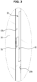
- FIG. 3 is an enlarged view of a dotted line portion of FIG. 1 , particularly, an enlarged view of a handle of a first door and a switch of the first door according to an embodiment of the disclosure.
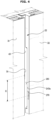
- FIG. 4 is a view illustrating a comparison between the switch of the first door and a switch of a second door according to an embodiment of the disclosure.
- the refrigerator 1 may include a main body 10, storage compartments 13 and 14 formed inside the main body 10, doors 21 and 22 configured to open the storage compartments 13 and 14, and a cold air supply device (not shown) configured to supply cold air to the storage compartments 13 and 14.
- the main body 10 may include an inner case 11 forming the storage compartments 13 and 14, an outer case 12 coupled to the outside of the inner case 11 to form an exterior, and an insulating material (not shown) provided between the inner case 11 and the outer case 12 to insulate the storage compartments 13 and 14.
- the storage compartments 13 and 14 may be partitioned into a storage compartment 13 on the left side and a storage compartment 14 on the right side by a vertical partition wall 15.
- the storage compartment 13 on the left side may be used as a freezing compartment
- the storage compartment 14 on the right side may be used as a refrigerating compartment.
- the division and use of the storage compartments 13 and 14 as described above is only an example, and is not limited thereto.
- a shelf 16 on which an item is placed and a storage container 17 for storing an item may be provided in the storage compartments 13 and 14.
- the cold air supply device may generate cold air using a refrigeration circulation cycle of compressing, condensing, expanding, and evaporating a refrigerant, and supply the generated cold air to the storage compartments 13 and 14.
- the refrigerator 1 may include the doors 21 and 22 configured to open and close the storage compartments 13 and 14.
- the door 21 on the left may open and close the storage compartment 13 on the left side
- the door 22 on the right may open and close the storage compartment 14 on the right side.
- the doors 21 and 22 may be rotatably coupled to the main body 10.
- Hinges 23, 24, and 25 may be provided in the main body 10 to rotatably couple the doors 21 and 22 to the main body 10.
- the left door 21 may be rotatably coupled to the main body 10 by a left upper hinge 23 and a left lower hinge 24.
- the right door 22 may be rotatably coupled by a right upper hinge 25 and a right lower hinge (not shown).
- a door shelf 26 to store food and a gasket 27 that can be closely adhered to the front surface of the main body 10 so that the storage compartments 13 and 14 are sealed when the doors are closed may be provided.
- the door gasket 27 may include a magnet so as to be attached to the front surface of the main body 10 with a magnetic force.
- Front panels 31 and 32 may be coupled to front surfaces of the doors 21 and 22.
- the front panels 31 and 32 may be detachably coupled to the front surfaces of the doors 21 and 22.
- a top table 2 may be provided on an upper surface of the main body 10.
- the top table 2 may cover at least a portion of the upper hinges 23 and 25 and prevent the upper hinges 23 and 25 from being exposed to the outside.
- a door opening device 100 configured to open the doors 21 and 22 may be provided inside the top table 2.
- a door opening device receiver 3, in which the door opening device 100 is received, may be formed on a bottom surface of the top table 2, and the door opening device 100 may be received in the door opening device receiver 3.
- the door opening device 100 may be coupled to the bottom surface of the top table 2 to be received in the door opening device receiver 3.
- the door opening device 100 may be coupled to the bottom surface of the top table 2 through a fastening member 6.
- the top table 2 may be coupled to the upper surface of the main body 10 in a state in which the door opening device 100 is coupled to the top table 2.
- Opening and closing sensors 141 and 142 configured to detect opening and closing of the doors 21 and 22 may be provided inside the top table 2.
- the opening and closing sensors 141 and 142 may include a Hall sensor configured to detect a change in magnetic field and generate a voltage.
- a magnet (not shown) detected by the opening and closing sensors 141 and 142 may be provided on the doors 21 and 22.
- the opening and closing sensors 141 and 142 are not limited thereto, and may include various types of sensors such as an optical sensor and a proximity sensor.
- the door opening device 100 may open the doors 21 and 22 by pushing the rear surfaces of the doors 21 and 22 forward.
- the door opening device 100 may partially open the doors 21 and 22 to allow a user to open the doors 21 and 22 with little force.
- the door opening device 100 may include push rods 111 and 112 configured to move.
- the push rods 111 and 112 may include a first push rod 111 configured to open the first door 21 and a second push rod 112 configured to open the second door 22.
- Rod holes 5 through which the first push rod 111 and the second push rod 112 penetrate may be formed in a front surface 4 of the top table 2.
- a first handle 61 that is recessed may be formed on a side surface 43a of the first door 21 to allow a user to put his/her hand and to be gripped by the user.
- the first handle 61 may be recessed on the side surface 43a of the first door 21, but may be formed only in a part of a section between an upper end and a lower end of the first door 21 rather than in the entire section.
- a second handle 261 that is recessed may be formed on a side surface 243a of the second door 22 to allow a user to put his/her hand and to be gripped by the user.
- the second handle 261 may be recessed on the side surface 243a of the second door 22, but may be formed only in a part of a section between an upper end and a lower end of the second door 22 rather than in the entire section.
- the side surface 243a of the second door 22 may be formed to have a step (refer to FIG. 12 ). That is, a distance between a front portion 243b of the side surface 243a of the second door 22 and the side surface 43a of the first door 21 may be greater than a distance between a rear portion 243c of the side surface 243a of the second door 22 and the side surface 43a of the first door 21. Therefore, between the front portion243b of the side surface 243a of the second door 22 and the side surface 43a of the first door 21, a space 28 through which a user can put his/her hand to the first handle 61 and the second handle 261 may be formed.
- the second handle 261 may be formed on the front portion 243b of the side surface 243a of the second door 22.
- the door opening device 100 may be operated through switches 70 and 270.
- a user can operate the door opening device 100 by manipulating the switches 70 and 270.
- the switches 70 and 270 may be operated by a user's touch.
- the switches 70 and 270 may include a first switch 70 provided on the first door 21 and a second switch 270 provided on the second door 22.
- the first switch 70 may operate the door opening device 100 to allow the door opening device 100 to open the first door 21.
- the second switch 270 may operate the door opening device 100 to allow the door opening device 100 to open the second door 22.
- the first switch 70 may operate the door opening device 100 to allow the first push rod 111 to move forward and the second push rod 112 to move backward.
- the first push rod 111 may advance and press the first door 21 to open the first door 21.
- the second switch 270 may operate the door opening device 100 to allow the first push rod 111 to move backward and the second push rod 112 to move forward.
- the second push rod 112 may advance and press the second door 22 to open the second door 22.
- the first switch 70 may be provided on the side surface 43a of the first door 21.
- the first switch 70 may be located in front of the first handle 61 on the side surface 43a of the first door 21. Accordingly, the first switch 70 may be touched at the same time as a user grabs the first handle 61 with his/her hand.
- At least a portion of the first switch 70 may be provided to protrude from the side surface 43a of the first door 21. Due to this structure, a user can hold the first handle 61 more comfortably.
- the second switch 270 may be provided on the side surface 243a of the second door 22.
- the second switch 270 may be located in front of the second handle 261 on the side surface 243a of the second door 22. Accordingly, the second switch 270 may be touched at the same time as a user grabs the second handle 261 with his/her hand.
- At least a portion of the second switch 270 may be provided to protrude from the side surface 243a of the second door 22. Due to this structure, a user can hold the second handle 261 more comfortably.
- heights of the first switch 70 and the second switch 270 may be different from each other. That is, the height of the first switch 70 and the height of the second switch 270 may differ by a predetermined height H.
- the height of the first switch 70 and the height of the second switch 270 are different, it is possible to prevent one of the first switch 70 and the second switch 270 from being unintentionally touched, and it is possible to prevent the malfunction of the door opening device 100.
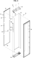
- FIG. 5 is a view illustrating a state in which the door and a front panel are separated according to an embodiment of the disclosure.
- FIG. 6 is a view illustrating a state in which the door and the front panel are separated according to an embodiment of the disclosure when viewed from another angle.
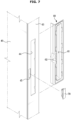
- FIG. 7 is a view illustrating a side member and a side cap of the door according to an embodiment of the disclosure.
- the doors 21 and 22 according to an embodiment of the disclosure will be described with reference to FIGS. 5 to 7 . Because configurations of the first door 21 and the second door 22 are almost similar, the first door 21 will be described and a description of the second door 22 will be omitted below.
- the door 21 may include a door front member 40 forming the front surface of the door 21, a door side member 43 forming the side surface of the door 21, and a door rear member 49 forming the rear surface of the door 21.
- the door front member 40 and the door side member 43 may be integrally formed with each other.
- the door front member 40 and the door side member 43 may be formed by bending a single metal plate.
- the door front member 40 and the door side member 43 may be formed separately from each other.
- the door front member 40 and the door side member 43 may be coupled to each other.
- a handle opening 44 and a switch opening 45 may be formed in the door side member 43. According to an embodiment, the handle opening 44 and the switch opening 45 may be formed separately and spaced apart from each other. The handle opening 44 may be formed larger than the switch opening 45. However, the size of the handle opening 44 and the switch opening 45 is not limited thereto. The handle opening 44 may be formed behind the switch opening 45.
- the handle opening 44 and the switch opening 45 may be formed to be connected to each other.
- the door 21 may include a side cap 60 coupled to an inner surface of the door side member 43.
- the side cap 60 may be coupled to the door side member 43 to cover the handle opening 44 and the switch opening 45. Because the side cap 60 is coupled to the inner surface of the door side member 43, the foaming solution may not leak through the handle opening 44 and the switch opening 45 when the insulating material is foamed in the inner space of the door 21.
- the side cap 60 may be injection molded of a plastic material. Because the side cap 60 is injection molded from a plastic material, various shapes may be easily formed on the side cap 60. For example, the handle 61 may be recessed in the side cap 60. In addition, a switch mounting space 62 in which the switch 70 is mounted may be formed in the side cap 60.
- the handle 61 may be formed in a size and shape substantially corresponding to the handle opening 44.
- the handle 61 may be accessible through the handle opening 44.
- the switch mounting space 62 may be formed to have a size and shape substantially corresponding to the switch opening 45.
- the door rear member 49 may be coupled to the door side member 43.
- the door gasket 27 (refer to FIG. 2 ) may be provided at an edge portion of the door rear member 49.
- the door rear member 49 may include a dyke protruding backward, and the door shelf 26 (refer to FIG. 2 ) may be mounted on the dyke.
- the door 21 may include an upper cap 50 and a lower cap 56.
- the door front member 40, the both door side members 43, the door rear member 49, the upper cap 50, and the lower cap 56 may be coupled to form an inner space.
- a door insulating material may be provided in the inner space.
- the upper cap 50 and the lower cap 56 may be injection molded from a plastic material.
- a structure for detachably coupling the front panel 31 to the front surface of the door 21 may be formed on the upper cap 50 and the lower cap 56.
- the switch 70 may be mounted in the switch mounting space 62 formed in the side cap 60.
- the switch 70 may be inserted into the switch mounting space 62 through the switch opening 45 formed in the door side member 43.
- the switch 70 may receive a user input for operating the door opening device 100.
- the switch 70 may receive a user input by a user's touch. That is, when a user touches the switch 70, the switch 70 may generate a signal to operate the door opening device 100.
- the switch 70 may include a touch switch configured to generate a door open signal according to capacitance change.
- the switch 70 may include switches of various other types other than a method of detecting a change in capacitance according to a touch.
- the switch 70 may include a mechanical push switch such as a button type, a dial type, or a toggle type.
- the switch may include a noncontact switch. That is, the switch may include a reed switch operated by a magnet, a proximity sensor switch including a proximity sensor, and a time of flight (TOF) switch including a TOF sensor using an infrared wavelength.
- TOF time of flight
- the refrigerator 1 may include the front panels 31 and 32 detachably coupled to front surfaces of the doors 21 and 22.
- the front panel 31 and the front panel 32 include the same or most similar configurations, and thus only the front panel 31 will be described.
- the front panel 31 may be detachably coupled to the front surface of the door 21.
- the front panel 31 may include a panel body 33, an upper trim 34 provided on an upper side of the rear surface of the panel body 33, and a lower trim 38 provided on a lower side of the rear surface of the panel body 33.
- the upper trim 34 may be elongated along an upper edge of the panel body 33.
- the lower trim 38 may be elongated along a lower edge of the panel body 33.
- the upper trim 34 and the lower trim 38 may be provided separately from the panel body 33, and attached to the panel body 33 through an adhesive. Alternatively, the upper trim 34 and the lower trim 38 may be integrally formed with the panel body 33.
- the lower trim 38 When the front panel 31 is coupled to the door 21, the lower trim 38 may be supported by the lower cap 56.
- the upper trim 34 may be coupled to the upper cap 50 through a fixer 55.
- the upper trim 34 When the front panel 31 is coupled to the door 21, the upper trim 34 may be inserted into the upper cap 50 through a trim opening 53 of the upper cap 50.
- the fixer 55 When the front panel 31 is coupled to the door 21, the fixer 55 may be coupled to the upper trim 34 through a fixer opening 54 formed on the upper side of the upper cap 50. With this configuration, the front panel 31 may be detachably coupled to the door 21.
- the front panel 31 may include a magnet 37 for coupling with the door 21.
- the magnet 37 may be provided to extend vertically on left and right edges of the panel body 33. With magnetic force, the magnet 37 may be in close contact with the door front member 40 formed of a metal.
- FIG. 8 is a view illustrating a vicinity of a lower hinge of the refrigerator according to an embodiment of the disclosure.
- FIG. 9 is a view illustrating a cam unit according to an embodiment of the disclosure, particularly, a view illustrating the cam unit in a state in which the door is closed.
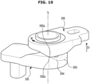
- FIG. 10 is a view illustrating the cam unit according to an embodiment of the disclosure, particularly, a view illustrating the cam unit in a state in which the door is opened (particularly, a state in which a push rod is at a maximum forward position of the push rod).
- cam unit according to an embodiment of the disclosure will be described with reference to FIGS. 8 to 10 .
- the refrigerator 1 includes the cam unit 180 configured to automatically close the doors 21 and 22. Because the cam unit 180 is applicable to both the first door 21 and the second door 22, only the cam unit 180 of the first door 21 will be described and a description of the cam unit 180 of the second door 22 will be omitted.
- the cam unit 180 may allow the door 21 to be closed by itself when no external force is applied in a state in which the door 21 is opened at a predetermined opening angle or less.
- the cam unit 180 may allow the door 21 to be closed by itself due to a weight of the door 21.
- the cam unit 180 may include a door cam 181 provided in a lower portion of the door 21 and a hinge cam 191 provided on the lower hinge 24.
- the door cam 181 may be fixed to the lower portion of the door 21, and the hinge cam 191 may be fixed to the lower hinge 24.
- the door cam 181 may also be rotated above the hinge cam 191.
- a leg 199 supporting a load of the main body 10 may be provided below the lower hinge 24.
- a hinge cam peak 192 and a hinge cam valley 193 may be alternately formed along a circumferential direction around a rotation axis X of the door 21.
- a door cam valley 183 and a door cam peak 182 may be alternately formed to correspond to the hinge cam peak 192 and the hinge cam valley 193.
- the door cam peak 182 When the door 21 is in a closed state, the door cam peak 182 may be engaged with the hinge cam valley 193, and the door cam valley 183 may be engaged with the hinge cam peak 192 (refer to FIG. 9 ).
- the door cam 181 When the door 21 is rotated in an opening direction R around the rotation axis X, the door cam 181 may also be rotated together. As the door cam 181 is rotated, the door cam 181 may ascend along an inclined surface 194 between the hinge cam valley 193 and the hinge cam peak 192.
- the door 21 When an external force applied to the door 21 disappears in a state in which a lowest part 182a of the door cam peak does not reach a highest part 192a of the hinge cam peak, the door 21 may be forced downward by its own weight. Accordingly, the door 21 may be closed by rotating in the opposite direction to the opening direction R along the inclined surface 194 between the hinge cam peak 192 and the hinge cam valley 193.
- FIG. 11 is an exploded view illustrating the door opening device according to an embodiment of the disclosure.
- FIG. 12 is a view illustrating a state in which a first push rod of the door opening device is in a neutral position of the first push rod and a second push rod is in a neutral position of the second push rod according to an embodiment of the disclosure.
- FIG. 13 is a view illustrating a state in which the first push rod of the door opening device is at the maximum forward position and the second push rod of the door opening device is at a maximum backward position according to an embodiment of the disclosure.
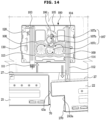
- FIG. 14 is a view illustrating a state in which the first push rod of the door opening device is at a maximum backward position and the second push rod of the door opening device is at a maximum forward position according to an embodiment of the disclosure.
- the door opening device 100 may include cases 101 and 102, a motor 105 provided inside the cases 101 and 102, the pair of push rods 111 and 112 configured to move forward and backward by the driving force generated in the motor 105, and a transmission gear assembly 107 configured to transmit the driving force of the motor 105 to the pair of push rods 111 and 112.
- the cases 101 and 102 may include an upper case 101 and a lower case 102 coupled to a lower portion of the upper case 101.
- the motor 105 and the transmission gear assembly 107 may be received inside the cases 101 and 102.
- a portion of the push rods 111 and 112 may pass through the cases 101 and 102 and protrude out of the cases 101 and 102.
- the pair of push rods 111 and 112 may be configured to move forward and backward, respectively.
- the pair of push rods 111 and 112 may be configured to move in opposite directions at the same time.
- the pair of push rods 111 and 112 may be configured to move at the same speed in opposite directions.
- a pair of movement guides 103 and 104 provided to guide movement of the pair of push rods 111 and 112 may be arranged inside the cases 101 and 102.
- the pair of push rods 111 and 112 may be movably coupled to the pair of movement guides 103 and 104, respectively, and may move forward and backward along with the movement guides 103 and 104.
- the pair of movement guides 103 and 104 may be arranged parallel to each other.
- the motor 105 may be a motor capable of forward and reverse driving.
- the motor 105 may include a DC stepper motor.
- a motor gear 106 may be provided on a motor shaft of the motor 105 to rotate together with the motor shaft.
- a rotational force of the motor gear 106 may be transmitted to a pair of pinion gears 108 and 109 through the transmission gear assembly 107.
- Rack gears 113 and 114 engaged with the pinion gears 108 and 109 may be provided on the push rods 111 and 112. A rotational motion of the pinion gears 108 and 109 may be converted into a linear motion of the rack gears 113 and 114.
- a first rack gear 113 may be engaged with the first pinion gear 108 to allow the first push rod 111 to move forward when the first pinion gear 108 rotates counterclockwise, and to allow the first push rod 111 to move backward when the first pinion gear 108 rotates clockwise.
- a second rack gear 114 may be engaged with the second pinion gear 109 to allow the second push rod 112 to move backward when the second pinion gear 109 rotates counterclockwise, and to allow the second push rod 112 to move forward when the second pinion gear 109 rotates clockwise.
- the transmission gear assembly 107 may include at least one transmission gear 107a, 107b, and 107c.
- the number of transmission gears included in the transmission gear assembly 107 is not limited thereto.
- the transmission gears 107a, 107b, and 107c may have the form of two-stage spur gear to reduce the rotational force of the motor 105 and transmit the reduced rotation force to the pair of pinion gears 108 and 109. That is, the transmission gears 107a, 107b, and 107c may include an upper spur gear and a lower spur gear having a radius smaller than that of the upper spur gear.
- the motor gear 106 may be engaged with an upper spur gear of the first transmission gear 107a.
- a lower spur gear of the first transmission gear 107a may be engaged with an upper spur gear of the second transmission gear 107b.
- a lower spur gear of the transmission gear 107b may be engaged with an upper spur gear of the third transmission gear 107c.
- a lower spur gear of the third transmission gear 107c may be engaged with the first pinion gear 108 and the second pinion gear 109.
- the first pinion gear 108 and the second pinion gear 109 may be engaged with the left and right sides of the third transmission gear 107c, respectively. Therefore, when the third transmission gear 107c rotates, the first pinion gear 108 and the second pinion gear 109 may rotate in different directions.
- the door opening device 100 may include a position detection sensor 130 configured to detect a position of the push rods 111 and 112.
- the position detection sensor 130 may include a Hall sensor configured to sense a change in a magnetic field and generate a voltage.
- a magnet 120 provided to be detected by the position detection sensor 130 may be provided in one of the plurality of push rods 111 and 112.
- the position detection sensor 130 is not limited thereto, and may include various types of sensors such as an optical sensor and a proximity sensor.
- the first push rod 111 and the second push rod 112 may move at the same speed in opposite directions, and thus when a position of one of the first push rod 111 and the second push rod 112 is detected, a position of the other of the first push rod 111 and the second push rod 112 may be detected. Accordingly, it may be sufficient that the position detection sensor 130 and the magnet 120 are configured to detect the position of one of the plurality of push rods 111 and 112.
- the door opening device 100 may open the first door 21 or the second door 22 according to the driving direction of the motor 105 (i.e., the rotation direction of the motor shaft). For example, when the motor 105 rotates in a forward direction (e.g., counterclockwise when viewed from above), the first push rod 111 of the door opening device 100 may move forward to open the first door 21. When the motor 105 rotates in a reverse direction (e.g., clockwise when viewed from above), the second push rod 112 of the door opening device 100 may move forward to open the second door 22.
- a forward direction e.g., counterclockwise when viewed from above
- a reverse direction e.g., clockwise when viewed from above
- the second push rod 112 of the door opening device 100 may move forward to open the second door 22.
- the driving direction of the motor 105 may be determined according to manipulation of the switches 70 and 270. For example, when the first switch 70 is operated, the motor 105 may be driven in the forward direction to allow the first door 21 to be opened. When the second switch 270 is operated, the motor 105 may be driven in the reverse direction to allow the second door 22 to be opened.
- the first push rod 111 and the second push rod 112 may initially be in a neutral position (refer to FIG. 12 ).
- the first push rod 111 When the motor 105 is driven in the forward direction in a state in which the first push rod 111 and the second push rod 112 are in the neutral position, the first push rod 111 may move forward and the second push rod 112 may move backward. The first push rod 111 may push the first door 21 while moving forward, so as to open the first door 21.
- the first push rod 111 may move forward to the maximum forward position of the first push rod and the second push rod 112 may move backward to the maximum backward position of the second push rod (refer to FIG. 13 ).
- the second push rod 112 may be at the maximum backward position of the second push rod.
- An opening angle of the door 21 when the first push rod 111 is at the maximum forward position of the first push rod may be an angle in which the lowest part 182a of the door cam peak does not reach the highest part 192a of the hinge cam peak (refer to FIG. 10 ). Accordingly, in this state, when the first push rod 111 moves backward, the door 21 may be closed by itself by the cam unit 180.
- the first push rod 111 When the motor 105 is driven in the reverse direction in a state in which the first push rod 111 is at the maximum forward position of the first push rod and the second push rod 112 is at the maximum backward position of the second push rod 112, the first push rod 111 may move backward and the second push rod 112 may move forward.
- the first push rod 111 may move backward and the second push rod 112 may move forward. Accordingly, the first push rod 111 and the second push rod 112 may return to the neutral positions thereof.
- the first push rod 111 When the motor 105 is driven in the reverse direction in a state in which the first push rod 111 and the second push rod 112 are in the neutral position, the first push rod 111 may move backward and the second push rod 112 may move forward. The second push rod 112 may push the second door 22 while moving forward, so as to open the second door 22.
- the first push rod 111 may move backward to the maximum backward position of the first push rod, and the second push rod 112 may move forward to the maximum forward position of the second push rod (refer to FIG. 14 ).
- the second push rod 112 may be at the maximum forward position of the second push rod.
- FIG. 15 is a control block diagram of the refrigerator according to an embodiment of the disclosure.
- FIG. 16 is a control flowchart of the refrigerator according to an embodiment of the disclosure, particularly a control flowchart in a state in which a second switch is not turned on in opening of the first door, waiting of the first door and closing of the first door.
- FIGS. 15 and 16 A control method of the refrigerator according to an embodiment of the disclosure will be described with reference to FIGS. 15 and 16 .
- the first switch 70 is turned on (i.e., when a user input is received) in a state where the first push rod 111 and the second push rod 112 are each in the neutral position
- the second switch 270 is turned on in a state in which the first push rod 111 and the second push rod 112 are in the neutral position, it may be controlled correspondingly.
- the refrigerator 1 may include a controller 150 configured to control the motor 105 and a speaker 160 according to a user input received by the switches 70 and 270, and the positional information of the push rods 111 and 112 detected by the position detection sensor 130.
- the controller 150 may output a notification sound through the speaker 160 (11). As the notification sound is output through the speaker 160, a user can recognize that the door opening device 100 starts to operate.
- the controller 150 may drive the motor 105 in the forward direction until the first push rod 111 reaches the forward position of the first push rod 111 from the neutral position of the first push rod (12 and 13). As the motor 105 is driven in the forward direction, the first push rod 111 may move forward and the second push rod 112 may move backward. The first door 21 may be opened as the first push rod 111 moves forward to push the first door 21.
- the controller 150 may determine whether the first push rod 111 reaches the maximum forward position through the position detection sensor 130 (13).
- the controller 150 may determine whether the first push rod 111 reaches the maximum forward position and perform at least one of stopping the motor 105 or slightly moving the motor 105 in the reverse direction before a predetermined waiting time elapses from when the first push rod 111 reaches the maximum forward position of the first push rod (14 to 16).
- the slight movement of the motor 105 in the reverse direction may include driving the motor 105 at low speed (a first reference driving speed) in the reverse direction.
- the opening angle of the first door 21 when the first push rod 111 is at the maximum forward position of the first push rod may be an angle in which the lowest part 182a of the door cam peak does not reach the highest part 192a of the hinge cam peak (refer to FIG. 10 ).
- the controller 150 may turn on a timer to set an elapsed time T as '0(zero)' (15).
- the controller 150 checks whether the elapsed time T of the timer is greater than or equal to a waiting time (16).
- the waiting time may be preset as a first reference waiting time T1.
- the controller 150 may stop the motor 105 throughout the waiting time from when the first push rod 111 reaches the maximum forward position of the first push rod 111. In addition, the controller 150 may drive the motor 105 in the reverse direction at the first reference driving speed throughout the waiting time from when the first push rod 111 reaches the maximum forward position of the first push rod 111.
- the controller 150 may stop the motor 105 for a part of the waiting time and move the motor 105 in the reverse direction at the first reference driving speed for the remaining part of the waiting time.
- the controller 150 may stop the motor 105 for a second reference waiting time T2, which will be described later, from when the first push rod 111 reaches the maximum forward position of the first push rod 111, and after the second reference waiting time T2 elapses, the controller 150 may drive the motor 105 in the reverse direction at the first reference driving speed for a third reference waiting time corresponding to a difference between the first reference waiting time T1 and the second reference waiting time T2.
- the first reference waiting time T1 may be 1 second
- the second reference waiting time T2 and the third reference waiting time may be 0.5 second, respectively.
- the first reference waiting time T1 may be set by a user.
- the second reference waiting time T2 may also be set by a user within a range shorter than the first reference waiting time T1.
- the refrigerator 1 may include a waiting time setting member 145 configured to allow a user to set the first reference waiting time T1 and/or the second reference waiting time T2.
- the motor 105 may stop or slightly move in the reverse direction, and thus the first push rod 111 may stop or move backward slowly. Accordingly, it is possible to secure a time for a user to pull the first door 21 by holding the handle 61. In addition, when a user does not pull the first door 21, the first door 21 may be closed smoothly, and noise and energy consumption due to a sudden change in direction of the motor 105 may be reduced.
- the controller 150 drives the motor 105 in the reverse direction (17). That is, the controller 150 may drive the motor 105 in the reverse direction at the second reference driving speed until the first push rod 111 returns to the neutral position of the first push rod 111 after the waiting time elapses from when the first push rod 111 reaches the maximum forward position of the first push rod 111.
- the second reference driving speed may be greater than the first reference driving speed.
- the first reference driving speed may be 10% or less of the maximum speed of the motor 105, and the second reference driving speed may be about 60% of the maximum speed of the motor 105.
- the first push rod 111 may move backward, and thus the first door 21 may be closed by itself by the cam unit 180. In this way, when a user does not pull the first door 21 for a predetermined waiting time, the first door 21 may be closed again by itself. Thus, it is possible to prevent the leakage of the cold air in the storage compartment.
- the controller 150 may detect the position of the first push rod 111 through the position detection sensor 130 to determine whether the first push rod 111 returns to the neutral position (18).
- the controller 150 may stop the motor 105 (19).
- control method of the refrigerator 1 may include opening the first door (12 and 13), waiting the first door (14 to 16), and closing the first door (17 and 18).
- the motor 105 may be driven in the forward direction until the first push rod 110 reaches the maximum forward position, so as to open the first door 21.
- the motor 105 may be driven in the reverse direction until the first push rod 110 returns to the neutral position, so as to close the first door 21.
- FIG. 17 is a control flowchart of the refrigerator according to an embodiment of the disclosure, particularly a part of the control flowchart including a state in which the second switch is turned on in the opening of the first door.
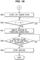
- FIG. 18 is a control flowchart of the refrigerator according to an embodiment of the disclosure, particularly a remaining part of the control flowchart including a state in which the second switch is turned on in the opening of the first door.
- the control method of the refrigerator may include outputting a notification sound (31), in which a notification sound is output through the speaker 160 in response to a user input being received by the second switch 270, in one of opening the first door (22 to 24), waiting the first door (25 to 27), and closing the first door (28 and 29).
- a notification sound in which a notification sound is output through the speaker 160 in response to a user input being received by the second switch 270, in one of opening the first door (22 to 24), waiting the first door (25 to 27), and closing the first door (28 and 29).
- the control method of the refrigerator may change a waiting time from a first reference waiting time T1 to a second reference waiting time T2 in response to a user input being received by the second switch 270.
- the second reference waiting time T2 may be less than the first reference waiting time T1.
- the first push rod 111 and the second push rod 112 which are interlocked, to move in opposite directions through one motor 150, and thus when the first push rod 111 moves forward and is in a withdrawn state, the second push rod 112 may move backward and in an inserted state. Accordingly, when a user input is received by the second switch 270 while the first push rod 111 is in the withdrawn state, it may take a time for the second push rod 112 to move forward to open the second door 22.
- the controller 150 may output a notification sound through the speaker 160 (21). As the notification sound is output through the speaker 160, a user can recognize that the door opening device 100 starts to operate.
- the controller 150 may drive the motor 105 in the forward direction until the first push rod 111 reaches the forward position of the first push rod 111 from the neutral position of the first push rod 111 (22 to 24). As the motor 105 is driven in the forward direction, the first push rod 111 may move forward and the second push rod 112 may move backward. The first door 21 may be opened as the first push rod 111 moves forward to push the first door 21.
- the controller 150 may determine whether the first push rod 111 reaches the maximum forward position through the position detection sensor 130 (24).
- the controller 150 may determine whether the first push rod 111 reaches the maximum forward position and perform at least one of stopping the motor 105 or slightly moving the motor 105 in the reverse direction before the predetermined waiting time elapses from when the first push rod 111 reaches the maximum forward position of the first push rod (25 to 27).
- the slight movement of the motor 105 in the reverse direction may include driving the motor 105 at low speed (the first reference driving speed) in the reverse direction.
- the controller 150 may stop the motor 105 throughout the waiting time from when the first push rod 111 reaches the maximum forward position of the first push rod 111.
- the controller 150 may drive the motor 105 in the reverse direction at the first reference driving speed throughout the waiting time from when the first push rod 111 reaches the maximum forward position of the first push rod 111.
- the controller 150 may stop the motor 105 for a part of the waiting time and move the motor 105 in the reverse direction at the first reference driving speed for the remaining part of the waiting time.
- the controller 150 may stop the motor 105 for the second reference waiting time T2 from when the first push rod 111 reaches the maximum forward position of the first push rod 111, and after the second reference waiting time T2 elapses, the controller 150 may drive the motor 105 in the reverse direction at the first reference driving speed for the third reference waiting time corresponding to a difference between the first reference waiting time T1 and the second reference waiting time T2.
- the controller 150 may turn on the timer to set an elapsed time T as '0(zero)' (26).
- the controller 150 checks whether the elapsed time T of the timer is greater than or equal to a waiting time (27).
- the waiting time may be preset as a first reference waiting time T1.
- the controller 150 drives the motor 105 in the reverse direction (28). That is, the controller 150 may drive the motor 105 in the reverse direction at the second reference driving speed until the first push rod 111 returns to the neutral position of the first push rod 111 after the predetermined waiting time elapses from when the first push rod 111 reaches the maximum forward position of the first push rod 111.
- the second reference driving speed may be greater than the first reference driving speed.
- the first reference driving speed may be 10% or less of the maximum speed of the motor 105, and the second reference driving speed may be about 60% of the maximum speed of the motor 105.
- the controller 150 may detect the position of the first push rod 111 through the position detection sensor 130 to determine whether the first push rod 111 returns to the neutral position (29).
- the controller 150 may stop the motor 105 (30).
- control method of the refrigerator 1 may include the opening of the first door (22 to 24), the waiting of the first door (25 to 27), and the closing of the first door (28 and 29).
- the controller 150 may determine whether a user input is received by the second switch 270 in the opening of the first door (22 to 24) (23). In response to the user input not being received by the second switch 270 in the opening of the first door (22 to 24), the control method may enter the step 25, and in response to the user input being received by the second switch 270 in the opening of the first door (22 to 24), the control method may enter a step 31.
- the controller 150 may output a notification sound through the speaker 160 (31). Accordingly, a user can recognize that the door opening device 100 starts to operate, and it may be difficult for the user to recognize a delay time that is a time until the second door 22 is actually opened.
- the controller 150 may output a notification sound through the speaker 160.
- the controller 150 may change the waiting time in response to the user input being received by the second switch 270 while the controller 150 drives the motor 105 in the forward direction until the first push rod 111 reaches the maximum forward position of the first push rod 111 from the neutral position of the first push rod 111.
- the controller 150 may change the waiting time from the first reference waiting time T1 to the second reference waiting time T2.
- the second reference waiting time T2 may be less than the first reference waiting time T1. Accordingly, the delay time until the second door 22 is opened may actually be reduced.
- the first reference waiting time T1 may be 1 second
- the second reference waiting time T2 may be 0.5 second.
- the controller 150 may change the waiting time. Particularly, the controller 150 may change the waiting time from the first reference waiting time T1 to the second reference waiting time T2.
- the second reference waiting time T2 may be less than the first reference waiting time T1.
- the controller 150 may determine whether the first push rod 111 reaches the maximum forward position through the position detection sensor 130 (32).
- the controller 150 may stop the motor 105 and may slightly move the motor 105 in reverse direction (33).
- the controller 150 may turn on a timer to set an elapsed time T as '0(zero)' (34).
- the controller 150 checks whether the elapsed time T of the timer is greater than or equal to a waiting time (35). Because the waiting time is changed from the first reference waiting time T1 to the second reference waiting time T2, the controller 150 may determine whether the elapsed time T of the timer is greater than or equal to the second reference waiting time T2.
- the first door 21 may wait for the second reference waiting time T2 in the waiting of the first door (33 to 35).
- the motor 105 may stop or slightly move in the reverse direction.
- the controller 150 drives the motor 105 in the reverse direction (36).
- the controller 150 may drive the motor 105 in the reverse direction at the second reference driving speed until the second push rod 112 reaches the maximum forward position of the second push rod 112 from the neutral position of the second push rod 112 (36 and 37).
- the controller 150 may determine whether the first push rod 111 reaches the maximum backward position of the first push rod 111 and whether the second push rod 112 reaches the maximum forward position of the second push rod 112 by detecting the position of the first push rod 111 through the position detection sensor 130 (37). That is, the controller 150 may determine whether the first push rod 111 reaches the maximum backward position of the first push rod 111 and whether the second push rod 112 reaches the maximum forward position of the second push rod 112 without determining whether the first push rod 111 reaches the neutral position.
- the controller 150 may stop the motor 105 and may slightly move the motor 105 in the forward direction (38).
- the driving of the motor 105 in the reverse direction at the second reference driving speed until the first push rod 111 returns to the neutral position of the first push rod 111, and the driving of the motor 105 in the reverse direction at the second reference driving speed until the second push rod 112 reaches the maximum forward position of the second push rod 112 from the neutral position of the second push rod 112 may be performed continuously.
- the first push rod 111 may move directly from the maximum forward position of the first push rod 111 to the maximum backward position of the first push rod 111 without stopping at the neutral position of the first push rod 111
- the second push rod 112 may move directly from the maximum backward position of the second push rod 112 to the maximum forward position of the second push rod 112 without stopping at the neutral position of the second push rod 112.
- the controller 150 may turn on the timer to set the elapsed time T as '0(zero)' (39). At this time, the waiting time may be reset to the first reference waiting time T1.
- the controller 150 determines whether the elapsed time T of the timer is greater than or equal to the waiting time (40).
- the controller 150 drives the motor 105 in the forward direction (41).
- the controller 150 may determine whether the first push rod 111 returns to the neutral position by detecting the position of the first push rod 111 through the position detection sensor 130 (42).
- the controller 150 may stop the motor 105 (43).
- the control method of the refrigerator 1 may include the outputting of the notification sound (31), the waiting of the first door (33 to 35), the closing of the first door and the opening of the second door (36 and 37), the waiting of the second door (38 to 40), and the closing of the second door (41 and 42).
- the closing of the first door and the opening of the second door may be continuously performed. Between the closing of the first door and the opening of the second door, the motor 105 may be continuously driven without stopping.
- the determination of the controller 150 in which the first push rod 111 is in the maximum forward position may be the same as the determination in which the second push rod 112 is in the maximum backward position
- the determination in which the first push rod 111 is in the maximum backward position may be the same as the determination in which the second push rod 112 is in the maximum forward position
- the determination in which the first push rod 111 is in the neutral position may be the same as the determination in which the second push rod 112 is in the neutral position.
- the controller 150 may drive the motor 105 to allow the first push rod 111 and the second push rod 112 to align with each other based on the position information of the first push rod 111 and the second push rod 112 detected by the position detection sensor 130, and the opening and closing information of the first door 21 and the second door 22 detected by the opening and closing sensors 141 and 142.
- control method in a case where the second switch 270 is turned on in the opening of the first door (22 to 24) has been described.
- the same or similar control method may be applied even when the second switch 270 is turned on in the waiting of the first door (25 to 27), and even when the second switch 270 is turned on in the closing of the first door (28 and 29).
- the controller 150 may output the notification sound and change the waiting time to the second reference waiting time T2.
- the controller 150 may output the notification sound.
- the controller 150 may control the motor 105 to allow the speed of the motor 105 in the reverse direction to be increased in the closing of the first door and the opening of the second door (36 and 37).
- the above-mentioned disclosure is not applied only to the above-described refrigerator, and may be applicable to a home appliance including a main body including a cavity, which is an internal space for performing a specific function, and a door configured to open and close the cavity, and the door thereof.
- the above-mentioned disclosure may be applied to a cooking appliance including a cooking chamber, a dishwasher including a washing chamber, a dryer including a drying chamber, a clothes treating apparatus including a clothes treating chamber, and an air conditioner including a heat exchange chamber in which a heat exchanger is disposed.
Landscapes
- Engineering & Computer Science (AREA)
- Chemical & Material Sciences (AREA)
- Combustion & Propulsion (AREA)
- Physics & Mathematics (AREA)
- Mechanical Engineering (AREA)
- Thermal Sciences (AREA)
- General Engineering & Computer Science (AREA)
- Refrigerator Housings (AREA)
Applications Claiming Priority (3)
| Application Number | Priority Date | Filing Date | Title |
|---|---|---|---|
| KR20220100903 | 2022-08-11 | ||
| KR1020220156774A KR20240022381A (ko) | 2022-08-11 | 2022-11-21 | 냉장고 및 그 제어 방법 |
| PCT/KR2023/011334 WO2024034988A1 (fr) | 2022-08-11 | 2023-08-02 | Réfrigérateur et procédé de commande associé |
Publications (2)
| Publication Number | Publication Date |
|---|---|
| EP4477978A1 true EP4477978A1 (fr) | 2024-12-18 |
| EP4477978A4 EP4477978A4 (fr) | 2025-07-16 |
Family
ID=89846933
Family Applications (1)
| Application Number | Title | Priority Date | Filing Date |
|---|---|---|---|
| EP23852868.1A Pending EP4477978A4 (fr) | 2022-08-11 | 2023-08-02 | Réfrigérateur et procédé de commande associé |
Country Status (2)
| Country | Link |
|---|---|
| US (1) | US20240053088A1 (fr) |
| EP (1) | EP4477978A4 (fr) |
Family Cites Families (3)
| Publication number | Priority date | Publication date | Assignee | Title |
|---|---|---|---|---|
| US8099970B2 (en) * | 2006-12-08 | 2012-01-24 | Samsung Electronics Co., Ltd. | Refrigerator door opening device and control method thereof |
| JP6492214B2 (ja) * | 2018-06-25 | 2019-03-27 | 日立アプライアンス株式会社 | 開扉装置及び開扉装置を備える機器 |
| JP7285086B2 (ja) * | 2019-02-18 | 2023-06-01 | ホシザキ株式会社 | 貯蔵庫 |
-
2023
- 2023-08-02 EP EP23852868.1A patent/EP4477978A4/fr active Pending
- 2023-08-18 US US18/235,665 patent/US20240053088A1/en active Pending
Also Published As
| Publication number | Publication date |
|---|---|
| EP4477978A4 (fr) | 2025-07-16 |
| US20240053088A1 (en) | 2024-02-15 |
Similar Documents
| Publication | Publication Date | Title |
|---|---|---|
| KR101655801B1 (ko) | 냉장고 도어 개폐장치 | |
| US10465975B2 (en) | Refrigerator | |
| KR20240022381A (ko) | 냉장고 및 그 제어 방법 | |
| KR101578354B1 (ko) | 냉장고 도어 개폐장치 | |
| EP4477978A1 (fr) | Réfrigérateur et procédé de commande associé | |
| EP4624838A1 (fr) | Réfrigérateur et appareil ménager | |
| KR20240022377A (ko) | 냉장고 | |
| US20250075966A1 (en) | Refrigerator | |
| US12560373B2 (en) | Refrigerator | |
| CN118974498A (zh) | 冰箱及其控制方法 | |
| US20260043598A1 (en) | Refrigerator | |
| KR20260023393A (ko) | 냉장고 | |
| US20250075964A1 (en) | Refrigerator | |
| KR20260025703A (ko) | 냉장고 | |
| KR20160091872A (ko) | 냉장고 도어 개폐장치 | |
| KR20260029995A (ko) | 가전 제품 및 그 제어 방법 | |
| US20260071809A1 (en) | Refrigerator and method for controlling the same | |
| US20260055652A1 (en) | Home appliance and method of controlling the same | |
| KR20260029985A (ko) | 가전 제품 | |
| KR20260029984A (ko) | 가전 제품 | |
| KR20250177613A (ko) | 냉장고 | |
| EP4624836A1 (fr) | Réfrigérateur | |
| KR20250033901A (ko) | 냉장고 | |
| KR20250054020A (ko) | 냉장고 및 이를 포함하는 가전 기기 | |
| KR20260020820A (ko) | 냉장고 및 그의 제어 방법 |
Legal Events
| Date | Code | Title | Description |
|---|---|---|---|
| STAA | Information on the status of an ep patent application or granted ep patent |
Free format text: STATUS: THE INTERNATIONAL PUBLICATION HAS BEEN MADE |
|
| PUAI | Public reference made under article 153(3) epc to a published international application that has entered the european phase |
Free format text: ORIGINAL CODE: 0009012 |
|
| STAA | Information on the status of an ep patent application or granted ep patent |
Free format text: STATUS: REQUEST FOR EXAMINATION WAS MADE |
|
| 17P | Request for examination filed |
Effective date: 20240912 |
|
| AK | Designated contracting states |
Kind code of ref document: A1 Designated state(s): AL AT BE BG CH CY CZ DE DK EE ES FI FR GB GR HR HU IE IS IT LI LT LU LV MC ME MK MT NL NO PL PT RO RS SE SI SK SM TR |
|
| A4 | Supplementary search report drawn up and despatched |
Effective date: 20250613 |
|
| RIC1 | Information provided on ipc code assigned before grant |
Ipc: F25D 29/00 20060101AFI20250606BHEP Ipc: F25D 23/02 20060101ALI20250606BHEP Ipc: E05F 15/614 20150101ALI20250606BHEP Ipc: E05F 15/75 20150101ALI20250606BHEP |
|
| DAV | Request for validation of the european patent (deleted) | ||
| DAX | Request for extension of the european patent (deleted) |