EP4478046A2 - Compteur de gaz avec détection automatique de configuration et procédé de configuration - Google Patents
Compteur de gaz avec détection automatique de configuration et procédé de configuration Download PDFInfo
- Publication number
- EP4478046A2 EP4478046A2 EP24176492.7A EP24176492A EP4478046A2 EP 4478046 A2 EP4478046 A2 EP 4478046A2 EP 24176492 A EP24176492 A EP 24176492A EP 4478046 A2 EP4478046 A2 EP 4478046A2
- Authority
- EP
- European Patent Office
- Prior art keywords
- gas
- extension module
- measuring device
- base part
- gas measuring
- Prior art date
- Legal status (The legal status is an assumption and is not a legal conclusion. Google has not performed a legal analysis and makes no representation as to the accuracy of the status listed.)
- Pending
Links
Images



Classifications
-
- G—PHYSICS
- G01—MEASURING; TESTING
- G01N—INVESTIGATING OR ANALYSING MATERIALS BY DETERMINING THEIR CHEMICAL OR PHYSICAL PROPERTIES
- G01N33/00—Investigating or analysing materials by specific methods not covered by groups G01N1/00 - G01N31/00
- G01N33/0004—Gaseous mixtures, e.g. polluted air
- G01N33/0009—General constructional details of gas analysers, e.g. portable test equipment
- G01N33/0073—Control unit therefor
-
- G—PHYSICS
- G01—MEASURING; TESTING
- G01N—INVESTIGATING OR ANALYSING MATERIALS BY DETERMINING THEIR CHEMICAL OR PHYSICAL PROPERTIES
- G01N33/00—Investigating or analysing materials by specific methods not covered by groups G01N1/00 - G01N31/00
- G01N33/0004—Gaseous mixtures, e.g. polluted air
- G01N33/0009—General constructional details of gas analysers, e.g. portable test equipment
-
- G—PHYSICS
- G01—MEASURING; TESTING
- G01N—INVESTIGATING OR ANALYSING MATERIALS BY DETERMINING THEIR CHEMICAL OR PHYSICAL PROPERTIES
- G01N33/00—Investigating or analysing materials by specific methods not covered by groups G01N1/00 - G01N31/00
- G01N33/0004—Gaseous mixtures, e.g. polluted air
- G01N33/0009—General constructional details of gas analysers, e.g. portable test equipment
- G01N33/0027—General constructional details of gas analysers, e.g. portable test equipment concerning the detector
- G01N33/0031—General constructional details of gas analysers, e.g. portable test equipment concerning the detector comprising two or more sensors, e.g. a sensor array
-
- G—PHYSICS
- G01—MEASURING; TESTING
- G01N—INVESTIGATING OR ANALYSING MATERIALS BY DETERMINING THEIR CHEMICAL OR PHYSICAL PROPERTIES
- G01N33/00—Investigating or analysing materials by specific methods not covered by groups G01N1/00 - G01N31/00
- G01N33/0004—Gaseous mixtures, e.g. polluted air
- G01N33/0009—General constructional details of gas analysers, e.g. portable test equipment
- G01N33/0062—General constructional details of gas analysers, e.g. portable test equipment concerning the measuring method or the display, e.g. intermittent measurement or digital display
- G01N33/0063—General constructional details of gas analysers, e.g. portable test equipment concerning the measuring method or the display, e.g. intermittent measurement or digital display using a threshold to release an alarm or displaying means
Definitions
- the invention relates to a configurable arrangement comprising a gas measuring device, wherein the arrangement is able to automatically recognize its own current configuration, as well as a configuration method for configuring such an arrangement.
- the invention is based on the object of providing an arrangement comprising a gas measuring device and at least one extension module, wherein the arrangement can be used in different configurations and wherein the operational reliability of the gas measuring device is increased compared to known arrangements. Furthermore, the invention is based on the object of providing a method for configuring such an arrangement.
- the arrangement according to the invention comprises a gas measuring device, which can also be referred to as a gas detection device or analysis device.
- the gas measuring device is designed to detect at least one specified gas in a gas sample, in particular a flammable and/or toxic gas for humans.
- a gas to be detected is referred to as a "target gas”.
- the gas sample comes from a spatial area to be monitored, for example from a building or vehicle or an area of a production plant or storage area.
- the gas measuring device comprises a base part, at least one gas sensor, a signal processing evaluation unit and at least one reading device.
- the base part preferably accommodates the gas sensor and a measuring chamber for the gas sample.
- the or each gas sensor is capable of measuring at least one detection variable, in particular an electrical detection variable.
- the or each detection variable correlates with the respective concentration of the or at least one target gas to be detected.
- the detection variable is greater, but sometimes smaller, the greater the target gas concentration.
- the detection variable correlates with the sum of several target gas concentrations.
- the evaluation unit is able to determine the concentration of the target gas or at least one target gas to be detected at least approximately. Optionally, the evaluation unit determines the summed concentration of several target gases. To determine the target gas concentration, the evaluation unit uses at least one measured value of the detection variable or at least one detection variable, optionally a time profile of the detection variable. Preferably, the evaluation unit applies a predetermined computer-evaluable calculation rule to the detection variable in order to determine the target gas concentration.
- the arrangement according to the invention comprises at least one extension module, optionally several extension modules.
- the or each extension module can be detachably connected to the base part, i.e. connected to the base part and also detached from the base part again.
- the connection is preferably a mechanical connection. If an extension module is connected to the base part, a possible movement of the extension module relative to the base part is limited. In one implementation, the connected extension module cannot perform any movement relative to the base part that is greater than a tolerance. If the extension module is detached from the base part, the extension module can generally be moved as desired relative to the base part.
- the terms "connect to the base part" and "detach from the base part" can, in addition to a mechanical connection, include the process of establishing a data connection between the base part and the extension module. to establish or interrupt or terminate this data connection. It is also possible for the base unit to supply a connected extension module with electrical energy.
- the arrangement comprises several extension modules.
- only one extension module can be connected to the base part at a time.
- several extension modules can be connected to the base part at the same time.
- the gas measuring device comprises at least one gas sensor.
- the or each gas sensor is capable of measuring a detection variable that correlates with a target gas concentration.
- the or each gas sensor belongs to the gas measuring device and is capable of measuring the detection variable, regardless of whether the or at least one extension module of the arrangement according to the invention is connected to the base part or the or each extension module is detached from the base part.
- the or at least one extension module comprises an extension module data memory.
- this extension module data memory an identification of the extension module is stored, in a form that can be evaluated by a computer. This identification distinguishes this extension module from any other or at least from any other type of extension module that can be detachably connected to the base part. In one embodiment, the identification distinguishes the extension module from the or any other extension module of the arrangement.
- the identification comprises, for example, an item number that identifies the type of extension module and a serial number that distinguishes this extension module from any similar extension module.
- the gas measuring device comprises at least one reading device.
- the or each reading device is preferably integrated into the base part.
- the or each reading device is able to read the extension module data memory of an extension module when the extension module is connected to the base part.
- the reading device is able to read the extension module data memory contactlessly. to read, i.e. to read even when there is a distance between the reader and the expansion module data memory.
- the reader is able to generate a signal, the signal comprising a result of reading the expansion module data memory.
- the signal comprises either a read-out identifier of an expansion module or a code indicating that the reader has not recognized an expansion module or the expansion module data memory and therefore could not read the identifier.
- the gas measuring device can automatically determine whether the or at least one extension module, which includes an extension module data storage device, is currently connected to the base unit or not. To do this, the gas measuring device processes the signal from the or at least one reading device. It is possible that the gas measuring device includes several reading devices and processes the respective signal from each reading device.
- the invention makes it possible to operate the same base part and thus the same gas sensor of a gas measuring device in conjunction with different extension modules and thus in different configurations.
- the gas measuring device can be adapted to different tasks and/or applications through the different configurations. Thanks to the invention, it is often not necessary to have a separate gas measuring device for each application and/or task. This saves components.
- the or a reading device of the gas measuring device reads a label that is stored on a data storage device of an extension module. Because the reading device reads the label without contact, in many cases it is not necessary to position the extension module exactly to be positioned correctly relative to the reader or to another sensor, such as a contact switch, on the base part. This feature reduces the risk of a connected extension module not being detected or of an incorrect extension module being identified. In addition, the risk of the label not being able to be correctly identified due to contamination or damage is lower than with a label that can be read optically.
- the gas measuring device can automatically react to the read-in label and determine that the relevant extension module is now connected to the base unit. Thanks to the invention, it is not necessary for a user to intervene in order to "tell" the gas measuring device that and which extension module or modules is/are currently connected to the base unit. This reduces the risk of the gas measuring device delivering an incorrect measurement result due to user error. In addition, time is saved in many cases. Conversely, the gas measuring device can automatically determine that it is not currently connected to one or a specific extension module.
- the gas measuring device is able to determine, depending on the signal from the reader, whether the extension module is connected to the base part or not.
- the gas measuring device preferably comprises a program which is stored in a data memory and is executed by a processor when the gas measuring device is used. This program evaluates the or each read-in marking and triggers a reaction from the gas measuring device, whereby this reaction depends on the read-in marking.
- the or a reader or an evaluation program determines the marking of an extension module, whereby this marking is stored in the extension module data memory and the reader reads in this marking.
- the gas measuring device automatically evaluates the read-in marking and reacts to the read-in marking by the gas measuring device carrying out a process which depends on the presence and/or type of marking.
- the gas measuring device is able to react automatically to the event that the reader has read the identification of this expansion module from an expansion module data memory.
- the reaction to the event depends on which identification was read in.
- different sets of identifications are defined, and the reaction depends on which of the predetermined sets the read identification belongs to.
- each possible identification of an expansion module is or includes an item number and a serial number, whereby all expansion modules with the same item number are identical and ideally only differ from one another in terms of their respective serial numbers.
- the reaction of the gas measuring device depends at least on the item number read in, optionally also on the serial number read in.
- the gas sensor measures a detection variable.
- the evaluation unit uses at least one measured value of the detection variable to determine the target gas concentration.
- the evaluation unit applies a functional relationship between the detection variable and the target gas concentration to the measured detection variable value or detection variable curve in order to derive the target gas concentration.
- the functional relationship is a proportionality factor or, more generally, a characteristic curve.
- the gas sensor of the gas measuring device is able to measure a detection variable.
- This detection variable correlates with the concentration of at least one target gas.
- at least two different functional relationships between the same detection variable and the concentration of the same target gas are stored in an evaluation data memory of the gas measuring device.
- the evaluation unit or a signal-processing control unit of the gas measuring device automatically selects a functional relationship and applies it to the detection variable value or detection variable curve. If an extension module of a certain type is connected to the base part, a first functional relationship is applied. If this If the extension module is not connected to the base part, another functional relationship is applied. The two functional relationships are different from each other. Connecting this extension module to the base part changes the dependence of the detection variable on the target gas concentration. The first relationship is valid and is applied if this extension module is connected to the base part, the other functional relationship if the extension module is not connected to the base part.
- three different functional relationships are specified and the arrangement includes two different extension modules. If no extension module is connected to the base part, a first functional relationship is applied, if the first extension module is connected, a second functional relationship, and if the second extension module is connected, a third functional relationship.
- the extension module changes the chemical composition and/or a physical property of a gas sample that flows from a spatial area to be monitored into a measuring chamber of the gas measuring device and that contains or can contain a target gas. For example, the extension module absorbs or changes part of a target gas.
- the detection size depends on the target gas concentration and additionally on an environmental condition, in particular on the ambient temperature and/or the ambient humidity and/or the ambient pressure.
- This environmental condition occurs in the first functional relationship, while in the further functional relationship a Standard value for this environmental condition occurs.
- the or an extension module comprises a sensor for this environmental condition. It is also possible for the extension module to comprise a receiver, wherein the receiver is designed to receive a signal from a spatially remote sensor for the environmental condition.
- the evaluation unit applies the first functional relationship, otherwise the other functional relationship.
- the gas detector uses a signal value from the ambient condition sensor and the first functional relationship to determine a target gas concentration.
- This design makes it possible in many cases to take the influence of the ambient condition into account relatively precisely when the extension module with the sensor measures or receives this ambient condition, and otherwise to use a standard value. Thanks to this design with the ambient condition sensor, the same base part can be used both in connection with the sensor and without the sensor. It is not necessary for a user to make a setting to specify whether an ambient condition sensor is connected to the base part or not.
- the or an extension module influences the length of time that a gas sample needs until the gas sample reaches the or a gas sensor of the gas measuring device.
- This gas sample comes from an environment of the gas measuring device.
- the extension module changes the distance over which a gas sample must flow until it reaches a measuring chamber and thus the or a gas sensor.
- This extension module comprises a hose or a tube or another fluid guide unit that can be detachably and fluid-tightly connected to the base part.
- This fluid guide unit has two ends, whereby when the fluid guide unit is mounted, one end covers an opening in the base part in a fluid-tight manner and the other end is connected to a spatial area that is to be monitored for the presence of a target gas.
- this extension module is connected to the base part, the following occurs: A gas sample from the spatial area flows through the fluid guide unit and the opening in the base part into the interior of the base part and cannot reach the interior and thus the gas sensor directly, i.e. bypassing the fluid guide unit. If the extension module is not connected to the base part, the gas sample can reach the interior directly through the opening, i.e. without having to flow through the fluid guide unit.
- the fluid guide unit it is not necessary to install the base part in the spatial area to be monitored.
- the fluid-tight fluid guide unit prevents gas from the immediate vicinity of the gas measuring device from reaching the gas sensor. If the fluid guide unit is not connected to the base part, the gas sample from the environment passes directly through the opening into the interior of the base part and thus to the gas sensor.
- the extension module connected to the base part extends the time period that elapses until a gas sample from the spatial area reaches the gas sensor, compared to an embodiment without this extension module.
- the evaluation unit takes this time period into account when determining the target gas concentration depending on the detection variable, preferably depending on the temporal progression of the detection variable.
- this embodiment makes it possible to generate a warning or an alarm regarding the presence of a target gas and/or a message about the absence of the target gas as early as possible, in which case this embodiment also ensures in many cases that a message that there is no target gas to be detected is only issued when a gas sample from the area to be monitored has reached a measuring chamber inside the base part. This means that the risk that neither a warning nor an alarm will be generated despite the presence of a target gas is relatively low.
- the gas measuring device comprises a base part and at least one gas sensor.
- the or each gas sensor of the gas measuring device is firmly connected to the base part. Therefore, it is not necessary to check with the aid of a reading device whether a gas sensor of the gas measuring device is connected to the base part or not.
- the or at least one extension module comprises a further gas sensor.
- the further gas sensor is also able to measure a detection variable that correlates with the concentration of a predetermined target gas. It is possible that both the detection variable that the gas sensor of the gas measuring device is able to measure and the detection variable that the further gas sensor of the extension module is able to measure relate to the same target gas. In many cases, this increases the reliability that a target gas is actually detected, namely by at least one gas sensor.
- An identification of the additional gas sensor is stored in the data memory of this extension module and is read in by the reader.
- the evaluation unit can also use a detection quantity value that the additional gas sensor, i.e. the gas sensor of the extension module, has measured.
- the additional gas sensor can measure a different detection variable than the gas sensor or gas sensors of the gas measuring device. This increases the application range of the arrangement.
- the additional gas sensor can measure the same detection variable as the gas sensor or gas sensors of the gas measuring device. In many cases, this leads to desired redundancy, particularly if the two gas sensors use different sensor principles. It is also possible that the additional gas sensor can be used in different environmental conditions, e.g. different temperature or humidity, than the gas sensor or gas sensors of the gas measuring device. The additional gas sensor can also have a different service life and/or a different reliability than the gas sensor or gas sensors of the gas measuring device.
- the additional gas sensor is a component of an extension module makes it possible to use the arrangement in one of several possible configurations. In a first configuration, only the or each gas sensor of the gas measuring device is used. In a second configuration, the additional gas sensor of the extension module is also used.
- the arrangement can comprise at least two different extension modules, each with an additional gas sensor.
- the two additional gas sensors i.e. the two gas sensors of the two extension modules, can be designed to measure the same detection quantity or to measure two different detection quantities.
- the gas measuring device can be switched on and off.
- the or at least one extension module comprises a protective element, in particular a closure cap. If this protective element is connected to the base part, the protective element separates an interior of the gas measuring device from the environment in a fluid-tight manner. If the protective element is attached, no gas sample can flow from a spatial area to be monitored into the interior of the gas measuring device.
- a connected protective element prevents harmful substances or even a cleaning fluid or water droplets from the environment from getting into the interior of the base part and thus to a gas sensor in the base part.
- a connected protective element often prevents a component of a gas sensor from evaporating, which can otherwise happen particularly with an electrochemical gas sensor.
- this protective element is a component of an extension module or forms an extension module. If the gas measuring device is switched on, the gas measuring device can automatically determine, thanks to the invention, whether the protective element is connected to the base part or not. For this purpose, the gas measuring device uses a signal from the or a reader, whereby this reader in turn receives an identification of the extension module with the protective element. If the protective element is connected to the base unit when the gas measuring device is switched on, the gas measuring device generates an alarm. The gas measuring device issues this alarm in at least one form that can be perceived by a human or causes an external output unit to issue this alarm in a form that can be perceived by a human. The alarm is issued in particular visually and/or acoustically and/or haptically (through vibrations).
- the or at least one extension module comprises a communication module.
- a data connection preferably a data connection via radio waves, can be established between the gas measuring device and a spatially distant receiver.
- this data connection can be established when this extension module is connected to the base part.
- the base part supplies the connected communication module with electrical energy.
- the gas measuring device can generate a message and cause the message to be sent to the spatially distant receiver via the established data connection. remote recipient.
- the message includes an identification of a target gas concentration that the gas sensor of the gas measuring device or optionally another gas sensor of an extension module has measured, and/or an identification of an alarm that the gas measuring device has generated.
- the design with the communication module as part of an extension module saves the need to permanently equip the gas measuring device with a communication module. Instead, it is possible to use the same gas measuring device to warn a user who is carrying the gas measuring device with them. The gas measuring device then often has an output unit for an alarm. A communication module is often not required in this case. On the other hand, the gas measuring device can be set up at one location and then transmits a message with the target gas concentration to the remote receiver. A communication module is required for this.
- a gas measuring device is to be used in an environment in which it cannot be connected to a stationary power supply network. Therefore, the gas measuring device preferably comprises its own power supply unit. For example, a user carries the gas measuring device with them while they are in a spatial area in which at least one target gas can occur. The gas measuring device then preferably has an output unit that can warn the user of a high target gas concentration. Or the gas measuring device is set up in a location where a target gas can occur. The gas measuring device then preferably comprises a communication unit, and a measured target gas concentration and/or an alarm is transmitted to a spatially distant receiver via this communication unit.
- the or an extension module comprises an external power supply unit.
- This external power supply unit can be electrically connected to the gas measuring device. If the extension module comprising the external power supply unit is connected to the base part, at least one electrical consumer of the Gas measuring device is at least temporarily supplied with power from this external power supply unit.
- this design avoids the need to provide the gas measuring device with an internal power supply unit. Instead, it allows the gas measuring device to be connected either to a stationary power supply network or to the external power supply unit. In some cases, this design therefore increases the flexibility with which the gas measuring device can be used.
- the gas measuring device includes an internal power supply unit. This is preferably located inside the base part. At least one electrical consumer, preferably every electrical consumer, can be supplied either from the external power supply unit of the extension module or from the internal power supply unit - the former of course only if the extension module is connected to the base part.
- a control unit of the gas measuring device has the following effect: If the extension module comprising the external power supply unit is connected to the base part and the electrical level of the external power supply unit is sufficiently high, the electrical consumers are supplied from the external power supply unit.
- the internal power supply unit is used when no external power supply unit is connected to the base part or the level of the external power supply unit has fallen below a predetermined limit.
- an external power supply unit can be replaced more quickly than an internal power supply unit. Therefore, the design with the external power supply unit makes it possible to quickly connect a new external power supply unit when the internal or the currently connected external power supply unit is running low.
- the replaced old external Power supply unit can be charged while the gas detector is being used with the new external power supply unit.
- the design just described is important in some cases, especially if the gas measuring device is to be used in an explosive environment and is therefore designed as an intrinsically safe device. It is often possible to replace an external power supply unit in the explosive environment. The internal power supply unit, however, can only be replaced or charged outside the explosive environment. The design just described therefore avoids the need to carry the gas measuring device out of the explosive environment and then bring it back into it later when the power supply unit is low.
- the gas measuring device is used to detect at least one harmful target gas in a spatial area, in particular a flammable or toxic target gas, or to ensure that no harmful target gas is present in this spatial area.
- the gas measuring device can detect several harmful target gases at the same time.
- the spatial area can in particular be a room that is completely or at least partially enclosed and belongs to a building or a vehicle, or also an area outdoors, for example a production plant or storage area.
- the gas measuring device is preferably able to measure at least the sum of the target gas concentrations.
- the gas measuring device comprises several gas sensors and is therefore able to measure the respective concentration of several harmful target gases in the spatial area and/or to automatically decide whether the concentration of the or a target gas is below or above a predetermined concentration limit.
- the gas measuring device is able to output at least one measured target gas concentration or an alarm in a form that can be perceived by a person, i.e. visually and/or acoustically and/or haptically (via vibrations).
- the gas measuring device is designed to transmit a target gas concentration or an alarm to a spatially distant receiver, which in turn outputs the received message.
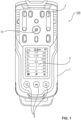
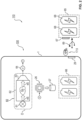
- FIG. 1 and Figure 2 show such a gas measuring device 100 in a perspective or a schematic representation.
- the gas measuring device 100 belongs to an arrangement 110, wherein the arrangement 110 additionally comprises various extension modules, which are described below.
- a housing 1 encloses a measuring chamber 62 in a fluid-tight manner and accommodates at least one gas sensor, preferably several gas sensors, in its interior.
- a gas sample Gp to be examined flows from the outside into the measuring chamber and reaches the gas sensors there.
- the gas sensors are preferably designed differently so that the gas measuring device 100 is able to detect several combustible target gases in the same gas sample Gp.
- redundancy is optionally created by having at least two gas sensors able to detect the same target gas, for example with two different sensor principles.
- the or each gas sensor of the gas measuring device 100 measures at least one detection variable.
- the or each detection variable correlates with the presence and/or concentration of a target gas to be detected.
- the detection variable is, for example, an electrical voltage or a current or an electrical charge or an electrical resistance.
- FIG 2 shows an example of a photoelectric sensor 60.
- a gas sample Gp to be examined flows from a spatial area to be monitored through an opening ⁇ into the measuring chamber 62.
- a radiation source 61 emits electromagnetic radiation eS into the measuring chamber 62.
- the electromagnetic radiation eS penetrates the measuring chamber 62 and thus the gas sample Gp at least once and hits a detector 63.
- a target gas to be detected in the gas sample Gp weakens the electromagnetic radiation eS.
- the detector 63 generates a signal, in this case an electrical voltage, which correlates with the intensity of the incident electromagnetic radiation eS.
- a voltage sensor 64 measures the electrical voltage generated by the detector 63. This electrical voltage is in the example of Figure 2 the detection variable, which correlates with the target gas concentration.
- a signal processing evaluation unit receives the measured value of the detection quantity or quantities from the or each gas sensor and derives an estimated value for the target gas concentration from the detection quantity value. For this derivation, the evaluation unit uses a predetermined computer-evaluable functional relationship to the detection quantity.
- the gas measuring device 100 further comprises a signal-processing control unit 26, also not shown.
- the evaluation unit is a component of the control unit 26. It is also possible that the evaluation unit is spatially removed from the control unit 26 or even from the gas measuring device 100.
- the evaluation unit comprises, for example, a program which is stored in a data memory of the control unit 26 and can run on a processor of the control unit 26. At least temporarily, the control unit 26 and thus the evaluation unit have read access to an evaluation data memory 27 in which at least one functional relationship between the detection variable and the target gas concentrations is stored.
- the gas measuring device 100 preferably comprises its own internal power supply unit 66, which is arranged inside the housing 1 and preferably comprises several rechargeable batteries (accumulators). This allows a user to carry the gas measuring device 100 with them while entering an area in which a target gas may be present.
- the gas measuring device 100 can be switched on and off. It is also possible to position the gas measuring device 100 stationary. Thanks to its own power supply unit 66, the gas measuring device 100 does not need to be connected to a stationary power supply network. It is also possible for the gas measuring device 100 to be positioned in a fixed location and connected to a stationary power supply network.
- the electrical consumers of the gas measuring device 100 can be supplied either by its own power supply unit or by a stationary power supply network.
- the gas measuring device 100 comprises a socket 29 into which a plug 69 of an extension module 65 can be inserted.
- the extension module 65 further comprises an external power supply unit 68.
- the electrical consumers 26, 61 of the gas measuring device 100 are then supplied with electrical energy by the internal power supply unit 66 when no external power supply unit 68 is connected. If the control unit 26 detects that an additional module 65 is connected to an external power supply unit 68, the control unit 26 causes the electrical consumers 26, 61 to be supplied by the external power supply unit 68.
- control unit 26 is able to determine the electrical fill level of the external voltage supply unit 68 and compare it with a predetermined lower fill level limit.
- the control unit 26 has the following effect: The electrical consumers 26, 61 are only supplied by the external voltage supply unit 68 if the supplementary module 65 is connected to the gas measuring device 100 and the measured fill level is above the lower fill level limit, and otherwise by the internal voltage supply unit 66.
- a plurality of inlets 2 are embedded in the housing 1, cf. Figure 1 and Figure 3 .
- the inlets 2 together establish a fluid connection between the environment of the gas measuring device 100 and the gas sensors inside the housing 1, for example the gas sensor 60 of Figure 2 .
- a display unit 4 and several operating elements 5 are also embedded in the housing 1, cf. Figure 1 .
- the gas measuring device 100 is able to visually output measurement results and/or alarms as well as messages about its own status.
- the gas measuring device 100 is able to generate an alarm and output this alarm visually and/or acoustically and/or haptically (through vibrations) if the measured concentration of a target gas or the sum of all target gas concentrations is above a predetermined concentration limit.
- a fluid diffuses from the environment of the gas measuring device 100 through the inlets 2 to the gas sensors inside the housing 1. This application is described in Figure 1 and Figure 3 It is also possible that a pump (not shown) sucks in the fluid.
- the Gas Detector 100 is used intermittently and is temporarily in a standby mode in which it is preferably switched off so that no electrical energy is consumed. It is often desired that the Gas measuring device 100 is not in fluid communication with the environment when at rest. Therefore, a cover cap 20 can be placed on the inlets 2 in a fluid-tight manner and then removed again.
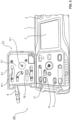
- Figure 3 shows schematically the cover cap 20 and an approximately rectangular area 11 of the surface of the housing 1, which is covered by the attached cover cap 20. When the cover cap 20 is attached, the gas measuring device 100 can be cleaned with a cleaning fluid without there being a risk of cleaning fluid getting into the interior of the housing 1.
- cover cap 20 when the cover cap 20 is attached, no harmful substances or water droplets from the environment can get into the interior of the gas measuring device 100. A user can place the cover cap 20 on the inlets 2 after use and remove it again before a new use. Of course, the cover cap 20 must not be attached during use, because then no gas sample can reach the measuring chamber and the gas measuring device 100 cannot detect a target gas.
- a grid unit 21 which is also approximately rectangular, can be placed on the area 11 with the inlets 2.
- the grid unit 21 reduces the risk of an insect or a larger particle getting into the interior of the housing 1 and damaging gas sensors.
- the grid unit 21 comprises a close-meshed grid 22 and a frame 23.
- a splash guard (not shown) on the area 11 of the inlets 2. This splash guard reduces the risk of drops of liquid getting into the interior of the housing 1 during use.
- the cover cap 20, the grille unit 21, the splash guard or none of these three components can be placed on the inlets 2.
- an adapter 3 can be placed fluid-tight onto the inlets 2 in the housing 1, cf. Figure 4 . If the adapter 3 is placed on the housing 1, the adapter 3 covers the area 11 and thus interrupts the fluid connection between the inlets 2 and the surroundings of the gas measuring device 100. With the cover cap 20 and the adapter 3 placed on, there is no fluid connection between the gas sensors in the housing 1 and the surroundings of the gas measuring device 100 due to through the inlets 2.
- a thread 13 for a screw 14 can be seen, whereby this screw 14 can hold the adapter 3 detachably to the housing 1.
- Figure 4 shows the adapter 3 (bottom) and a part of the housing 1 (top), with the elastic filling 6 pointing towards the viewer.
- the screw 14 can be screwed into the thread 13.
- the filling 6 is then located between the outer shell 9 and the gas sensors.
- a large number of fluid channels 10 are embedded in the filling 6. These fluid channels 10 establish fluid connections between the nozzle 12 and the gas sensors.
- a connecting element 7 can be placed on the nozzle 12 in a fluid-tight manner.
- This connecting element 7 can be connected in a fluid-tight manner to a fluid guide unit (not shown), in particular to a hose.
- a fluid conveying unit for example a pump, can be connected to the fluid guide unit. It is also possible to connect the fluid conveying unit directly to the connecting element 7. In another embodiment, the fluid conveying unit is arranged inside the housing 1.
- the gas measuring device 100 is able to suck in a gas sample to be examined. Before sucking in, the gas sample is located at a measuring position that is spaced apart from the gas measuring device 100.
- the connecting element 7, the nozzle 12 and the fluid channels 10 guide the sucked in gas sample to the sensors in the housing 1. It is possible that the gas sample comes from an enclosed space and the gas measuring device 100 is arranged outside this space. This protects the gas measuring device 100 to a certain extent from mechanical and chemical influences. protected that can occur in the enclosed space.
- the fluid-tight adapter 3 prevents gas from the environment of the gas measuring device 100 from reaching the gas sensors or a gas sample from inside the housing 1 from getting into the environment.
- a calibration station (not shown) supplies the gas measuring device 100 with at least one gas sample, preferably several different gas samples, wherein the or each gas sample contains a target gas to be detected with a known concentration.
- the calibration station comprises at least one compressed gas cylinder, wherein the or each compressed gas cylinder contains a target gas with a known concentration.
- the value of a detection variable of the gas measuring device 100 for this gas sample is measured.
- a relationship between the target gas concentration and the detection variable is automatically derived empirically from the measured values and the known concentrations and stored in a computer-evaluable form in the evaluation data memory 27. For example, a regression analysis is carried out or a neural network is trained.
- this additional adapter 3.1 is called a "calibration adapter".
- the external geometry of the calibration adapter 3.1 matches the external geometry of the adapter 3, so that either the adapter 3 or the calibration adapter 3.1 can be inserted into the housing 1.
- the attached calibration adapter 3.1 also completely covers the area 11 and prevents a fluid connection to the environment.
- Figure 4 shows the calibration adapter 3.1 in the middle, with the filling 6.1 facing the viewer.
- the screw 14.1 can be screwed into the thread 13.
- a large number of fluid channels 10.1 are embedded in the filling 6.1.
- a calibration connecting element 8 can be placed fluid-tight on the nozzle 12.1.
- This calibration connecting element 8 and an optional fluid guide unit (not shown) enable the calibration adapter 3.1 to be connected fluid-tight to the calibration station.
- a gas sample flows from the calibration station through the optional fluid guide unit, the calibration connecting element 8 and the fluid channels 10.1 to the gas sensors.
- the filling 6 of the adapter 3 and the filling 6.1 of the calibration adapter 3.1 are made of foam. This foam is placed in a flowable form in a hollow body, for example pressed, hardens there and is then removed from the hollow body again.
- the filling 6, 6.1 is connected to the outer shell 9, 9.1 in a form-fitting manner, for example by gluing, or is screwed.
- at least one plate is made from the foam and several copies of the filling 6, 6.1 are cut out of this plate. By cutting out, each filling 6, 6.1 is given the desired circumferential contour.
- the foam is applied to the outer shell 9, 9.1, with several hollow bodies being held close to the inside of the outer shell 9, 9.1. This causes the fluid channels 10, 10.1 to be formed. In addition, the foam bonds to the outer shell 9, 9.1 when it hardens.
- Figure 5 shows the calibration adapter 3.1 (top) and a part of the gas detection device 100 (bottom) before the calibration adapter 3.1 is placed on the housing 1.
- the filling 6.1 faces the viewer.
- Figure 6 shows the gas detection device 100 with the attached calibration adapter 3.1.
- the calibration adapter 3.1 covers the inlets 2.
- the outer shell 9.1 points towards the viewer.
- a knob 15.1 is rotatably connected to the outer shell 9.1 and non-rotatably connected to the screw 14.1 and allows the screw 14.1 to be turned from the outside.
- the nozzle 12.1 and the calibration connecting element 8 can also be seen.
- the gas measuring device 100 can therefore be used in different configurations. This configuration can be changed from application to application. According to the invention, the gas measuring device 100 can automatically recognize its current configuration to a certain extent.
- a reader 17, 17.5 is embedded in the housing 1, which is preferably designed as a transmitting-receiving unit.
- At least one, preferably every extension module carries a data memory that can be read from the outside. Examples are Figure 2 a data memory 67 for the extension module 65 and in Figure 3 to Figure 5 a data memory 19 for the cover cap 20, a data memory 24 for the grid unit 21, a data memory 18 for the adapter 3 and a data memory 18.1 for the calibration adapter 3.1.
- the reader 17, 17.5 is able to read each data memory 18, 18.1, 19, 24, 67 without contact, provided that the data memory 18, 18.1, 19, 24, 67 is located in a reading area of the reader 17, 17.5.
- this data memory 18, 18.1, 19, 24, 67 is attached to the extension module 3, 3.1, 20, 21, 65 in such a way that when the extension module 3, 3.1, 20, 21, 65 the data storage 18, 18.1, 19, 24, 67 is in the reading range of the reader 17, 17.5.
- the respective extension module is also not connected to the gas measuring device 100.
- each data storage device 18, 18.1, 19, 24, 67 is designed as a transponder chip ("tag"), preferably as an RFID chip.
- the reader 17, 17.5 is designed as an RFID reader. It is also possible for the reader 17, 17.5 to use another suitable method, for example Near Field Communication (NFC), Low Frequency (LF), High Frequency or Ultra High Frequency (UHF).
- NFC Near Field Communication
- LF Low Frequency
- UHF Ultra High Frequency
- a sequence of data carriers is applied to a tape, with one surface of this tape being connected to an adhesive layer.
- the tape is an adhesive film.
- One data storage device 18, 18.1, 19, 24, 67 per expansion module is applied to the adhesive layer.
- a part of the adhesive layer with the data storage device 18, 18.1, 19, 24, 67 is glued to a specific location on the surface of the expansion module 3, 3.1, 20, 21, 65.
- the data storage device 18, 18.1, 19, 24 is located between the expansion module 3, 3.1, 20, 21, 65 and the tape, so that the tape protects the data storage device 18, 18.1, 19, 24, 67 to a certain extent from environmental influences.
- the tape is permeable to electromagnetic waves.
- a housing or another component of the extension module 3, 3.1, 20, 21, 65 or even the complete extension module is manufactured by casting. While the component (component or extension module) is manufactured, the data storage device 18, 18.1, 19, 24, 67 is brought into the interior of this component and held there temporarily. The hardening casting material from which the component is manufactured surrounds the data storage device 18, 18.1, 19, 24, 67. The data storage device 18, 18.1, 19, 24 is therefore brought into the interior of the component by overmolding or by potting.
- At least the information about the type of extension module 3, 3.1, 20, 21, 65 to which this data storage device 18, 18.1, 19, 24, 67 is applied is stored on a data storage device 18, 18.1, 19, 24, 67. It is possible that a unique identifier is also stored that distinguishes the extension module from similar extension modules.
- properties of the extension module 3, 3.1, 20, 21, 65 are also stored. For example, a proportionality factor between a detection variable that the extension module is able to measure and a target gas concentration is stored in the data storage device, or a period of time that elapses until a gas sample has flowed through the extension module into the interior of the gas measuring device 100.
- the gas sensors are fixedly arranged inside the housing 1.
- an extension module which includes an external gas sensor, can be detachably connected to the gas measuring device - more precisely: to the base part.
- the internal gas sensor 44 is capable of measuring a detection quantity which correlates with the concentration of at least one target gas.
- the internal gas sensor 44 can be constructed in the same way as the gas sensor 60 which is described with reference to Figure 2
- the internal gas sensor 44 can also be a photoacoustic or electrochemical sensor or a heat-tone sensor.
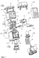
- Various in Figure 7 The extension modules shown each have a data memory that can be read from the outside. These data memories are stored in Figure 7 not shown.
- the housing unit 30 and the measuring unit 31 are firmly connected to one another.
- the two units 30, 31 are detachably connected to one another, for example using snap fasteners or locking fasteners or screw fasteners. If the two units 30, 31 are connected to one another, they form a base part to which various expansion modules can be detachably connected. It is also possible for only the housing unit 30 to form a base part and the measuring unit 31 to form an expansion module.
- the reader 17.4 of the housing unit 30 is preferably able to read a data memory on the measuring unit 31.
- a sensor extension module 50 with an external gas sensor 34 and a connector 36 can be detachably connected to the sensor connection 32. connect and optionally screw on.
- the gas sensor 34 is also able to measure a detection variable that correlates with the concentration of a combustible target gas.
- the connecting piece 36 can be put on and screwed in. If the connecting piece 36 is connected to the sensor connection 32, the gas sensor 34 is supplied with electrical energy via a connecting line 35.
- the reading device 17.3 is able to read a data memory on the sensor extension module 50, whereby this data memory is preferably located on the connecting piece 36.
- the control device 26 automatically recognizes the type of gas sensor 34 and parameters the measuring unit 31 accordingly. It is possible that the internal gas sensor 44 is able to detect a first target gas and the external gas sensor 34 is able to detect a second target gas.
- An adapter 39 for a pump (not shown) can be attached to the sensor connection 32.
- This pump can suck in a gas sample from a remote sampling location.
- the sucked in gas sample flows, for example, through a hose and the adapter 3 from Figure 4 to the gas sensor 44.
- the reader 17.3 is able to read a data memory on this adapter 39.
- a pump extension module 87 with a pump 37 can be placed on top of the housing unit 30.
- This pump 37 can suck in a gas sample and convey it to the gas sensor 44 of the measuring unit 31.
- two gas lines 88 namely a suction line and a pressure line, lead to the two openings 89 on the underside of the housing unit 30.
- the conveying direction of the pump 37 can preferably be reversed so that the gas sample can be conveyed either to the internal gas sensor 44 of the measuring unit 31 or to the external gas sensor 34 of the connected sensor extension module 50.
- the reader 17.4 can read a data memory on the pump extension module 87.
- a release module 40 can be detachably connected to the measuring unit 31. If the release module 40 is connected to the measuring unit 31, the release module 40 enables additional functions of the evaluation unit.
- the reader 17.2 can read a data memory on the release module 40 and thereby detect whether the release module 40 is connected to the measuring unit 31 or is missing.
- At least one communication module 41.1, 41.2 can be detachably connected to the measuring unit 31.
- the reading device 17.4 can read a data storage on a connected communication module 41.1, 41.2.
- the or at least one communication module 41.1 translates at least one signal from the gas measuring device 101 into a message according to a predetermined communication standard, preferably according to a mobile radio standard.
- the communication module 41.1 or another communication unit can transmit this message to a remote receiver according to the communication standard. This allows the gas measuring device 100 to be read remotely.
- a portable device 42 with a display is shown as an example as the receiver. Using this device 42, a user can read the gas measuring device 101 remotely.
- the or at least one communication module 41.2 receives a signal from a gas sensor (not shown) that is able to measure a detection variable.
- the evaluation unit in the control unit 26 activates a corresponding functional connection between this detection variable and a target gas concentration if such a communication module is detected.
- This gas sensor can be arranged spatially away from the gas measuring device 101.
- the measuring unit 31 of the gas measuring device 101 can evaluate a signal from the spatially distant gas sensor.
- a data storage device is arranged on the underside of the cover 33.
- the reading device 17.1 is able to read this data storage device on the cover 33.
- the cover 33 can be replaced by an extension module 77.
- the extension module 77 performs the mechanical function of the cover 33 and also contains an optional device, for example a temperature sensor or a humidity sensor or a pressure sensor or a sensor for another ambient condition.
- the reader 17.1 can read a data memory on the underside of the extension module 77.
- the evaluation unit in the control unit 26 activates another functional relationship in the above-mentioned data memory for functional relationships. This is because if the ambient temperature or the ambient humidity or the ambient pressure or the other ambient condition is measured, a functional relationship can be used in which the temperature or the humidity appears as a measured quantity. If such an extension module 77 is not detected, a default value for the ambient condition that is specified or set by a user is used.
- the control unit 26 determines the current configuration of the gas measuring device 100, i.e., determines which extension modules are currently connected to the actual gas measuring device 100 according to the signals from the reading devices 17, 17.1, ..., 17.4.
- a maintenance technician can read out the current configuration of the gas measuring device 100.
- the maintenance technician authorizes himself using a data storage device on a personal card by holding this personal card to a reading device 17, 17.1, ..., 17.4.
- Housing of the gas measuring device 100 accommodates the display unit 4 and the operating elements 5, surrounds the gas sensor 60, has the inlets 2 and the thread 13 2 Inlets in the housing 1, each establish a fluid connection between a sensor of the gas measuring device 100 and the environment, are arranged in the area 11 of the housing 1 3
- Adapter includes the outer shell 9, the filling 6 and the nozzle 12, can be detachably placed on the housing 1 and then covers the area 11, is used when using the gas measuring device 100 3.1
- Calibration adapter includes the outer shell 9.1, the filling 6.1 and the nozzle 12.1, can be detachably placed on the housing 1 and then covers the area 11, is used when calibrating the gas measuring device 100 4
- Filling of the adapter 3 is made of a foam 6.1
- Filling of the calibration adapter 3.1 is made of a foam 7 Connecting element that can be placed on the nozzle 12 and connected to a hose
Landscapes
- Chemical & Material Sciences (AREA)
- Life Sciences & Earth Sciences (AREA)
- Engineering & Computer Science (AREA)
- Health & Medical Sciences (AREA)
- Analytical Chemistry (AREA)
- Food Science & Technology (AREA)
- Medicinal Chemistry (AREA)
- Physics & Mathematics (AREA)
- Combustion & Propulsion (AREA)
- Biochemistry (AREA)
- General Health & Medical Sciences (AREA)
- General Physics & Mathematics (AREA)
- Immunology (AREA)
- Pathology (AREA)
- Investigating Or Analyzing Materials By The Use Of Electric Means (AREA)
- Investigating Or Analyzing Materials By The Use Of Fluid Adsorption Or Reactions (AREA)
Applications Claiming Priority (1)
| Application Number | Priority Date | Filing Date | Title |
|---|---|---|---|
| DE102023113906.1A DE102023113906A1 (de) | 2023-05-26 | 2023-05-26 | Gasmessgerät mit automatischer Erkennung der Konfiguration und Konfigurierungs-Verfahren |
Publications (2)
| Publication Number | Publication Date |
|---|---|
| EP4478046A2 true EP4478046A2 (fr) | 2024-12-18 |
| EP4478046A3 EP4478046A3 (fr) | 2025-03-12 |
Family
ID=91185041
Family Applications (1)
| Application Number | Title | Priority Date | Filing Date |
|---|---|---|---|
| EP24176492.7A Pending EP4478046A3 (fr) | 2023-05-26 | 2024-05-17 | Compteur de gaz avec détection automatique de configuration et procédé de configuration |
Country Status (3)
| Country | Link |
|---|---|
| US (1) | US20240393309A1 (fr) |
| EP (1) | EP4478046A3 (fr) |
| DE (1) | DE102023113906A1 (fr) |
Family Cites Families (9)
| Publication number | Priority date | Publication date | Assignee | Title |
|---|---|---|---|---|
| EP0472131B1 (fr) * | 1990-08-20 | 1996-10-30 | Hartmann & Braun Aktiengesellschaft | Procédé pour déterminer la concentration d'un composant d'un mélange gazeux contenant plusieurs composants en mesurant la conductivité thermique |
| US6837095B2 (en) * | 1999-03-03 | 2005-01-04 | Smiths Detection - Pasadena, Inc. | Apparatus, systems and methods for detecting and transmitting sensory data over a computer network |
| US6182497B1 (en) * | 1999-08-20 | 2001-02-06 | Neodym Systems Inc | Gas detection system and method |
| DE102011088012A1 (de) * | 2011-12-08 | 2013-06-13 | Endress + Hauser Conducta Gesellschaft für Mess- und Regeltechnik mbH + Co. KG | Sensorendmodul, Sensor und Messeinrichtung |
| US9557306B2 (en) * | 2013-12-20 | 2017-01-31 | Honeywell International Inc. | Magnetically controlled gas detectors |
| EP3248384B1 (fr) * | 2015-01-19 | 2019-06-26 | Honeywell International Inc. | Test de déclenchement et étalonnage automatiques dans des détecteurs de gaz par l'intermédiaire d'une communication sans fil à courte portée |
| WO2016131025A1 (fr) * | 2015-02-13 | 2016-08-18 | Ideation Systems Llc | Système modulaire comprenant plusieurs capteurs amovibles |
| WO2020225796A1 (fr) * | 2019-05-09 | 2020-11-12 | Q.E.D Environmental Systems Limited | Analyseur de gaz portatif |
| US12174166B2 (en) * | 2021-10-07 | 2024-12-24 | Msa Technology, Llc | Assignment and de-assignment in portable devices via a charger |
-
2023
- 2023-05-26 DE DE102023113906.1A patent/DE102023113906A1/de active Pending
-
2024
- 2024-05-17 EP EP24176492.7A patent/EP4478046A3/fr active Pending
- 2024-05-23 US US18/672,335 patent/US20240393309A1/en active Pending
Also Published As
| Publication number | Publication date |
|---|---|
| US20240393309A1 (en) | 2024-11-28 |
| EP4478046A3 (fr) | 2025-03-12 |
| DE102023113906A1 (de) | 2024-11-28 |
Similar Documents
| Publication | Publication Date | Title |
|---|---|---|
| EP3302340B1 (fr) | Système de détection de contenu de contenant chirurgical | |
| DE69708688T2 (de) | Überwachung und steuerung von sterilisierungsverfahren mit halbleitersensormodulen | |
| DE69727156T2 (de) | Autonomes elektronisches echtzeitsystem zur überwachung von ableitern, ventilen und anlagen | |
| DE112012004481B4 (de) | Universelles Werkzeug und Verfahren für ein Reifendrucküberwachungssystem | |
| DE10203814C2 (de) | Mobiles Kommunikationsendgerät | |
| WO2013104743A1 (fr) | Réceptacle de rangement et/ou de transport pour instruments médicaux et procédé permettant de détecter et de transférer des données relatives auxdits instruments médicaux | |
| DE102014201931A1 (de) | Steuervorrichtung, medizinisches Steuersystem und Verfahren zur Übertragung eines Befehls | |
| DE102017131076A1 (de) | Inline-Sensor und Fluidleitungssystem | |
| WO2016202730A1 (fr) | Dispositif de mesure pour déterminer des propriétés physiques, des propriétés chimiques, des propriétés biologiques et/ou des substances de l'environnement d'au moins un capteur ou de l'au moins un capteur faisant partie du dispositif de mesure | |
| DE202020107286U1 (de) | Sensorvorrichtung und Erweiterungsmodul | |
| DE102018213002A1 (de) | Vorrichtung und Verfahren zur Diagnose von Membranen | |
| DE102015102766A1 (de) | Verfahren zum Erfassen der Anzahl der Sterilisierungen eines Teils eines medizinischen Geräts | |
| EP1621863B1 (fr) | Dispositif de détection d'une fuite | |
| EP4478046A2 (fr) | Compteur de gaz avec détection automatique de configuration et procédé de configuration | |
| DE102016124796A1 (de) | Sensorkopfmodul zur kontinuierlichen automatisierten Datenerfassung | |
| EP3201593B1 (fr) | Plaque d'essai | |
| DE202016106929U1 (de) | Dichtungs- und/oder Brandschutzvorrichtung | |
| DE102022127706A1 (de) | Vorrichtung und verfahren zur erfassung aus der ferne | |
| DE102021100634B4 (de) | Gerät, System und Verfahren zur Verfolgung und/oder Lokalisierung medizinischer Instrumente in einem Reinigungs- und/oder Sterilisationsprozess | |
| EP1772707B1 (fr) | Dispositif de mesure | |
| WO2014177496A1 (fr) | Avertisseur de danger à capteur thermique | |
| EP3721183A1 (fr) | Dispositif de mesure fonctionnant sur batterie | |
| DE60008794T2 (de) | Gerät und system zur messung eines parameters in einem geschlossenen raum | |
| DE102014112261B4 (de) | Vorrichtung zur Strömungsmessung | |
| EP2196086A1 (fr) | Dispositif de surveillance de grands animaux |
Legal Events
| Date | Code | Title | Description |
|---|---|---|---|
| PUAI | Public reference made under article 153(3) epc to a published international application that has entered the european phase |
Free format text: ORIGINAL CODE: 0009012 |
|
| STAA | Information on the status of an ep patent application or granted ep patent |
Free format text: STATUS: THE APPLICATION HAS BEEN PUBLISHED |
|
| AK | Designated contracting states |
Kind code of ref document: A2 Designated state(s): AL AT BE BG CH CY CZ DE DK EE ES FI FR GB GR HR HU IE IS IT LI LT LU LV MC ME MK MT NL NO PL PT RO RS SE SI SK SM TR |
|
| PUAL | Search report despatched |
Free format text: ORIGINAL CODE: 0009013 |
|
| AK | Designated contracting states |
Kind code of ref document: A3 Designated state(s): AL AT BE BG CH CY CZ DE DK EE ES FI FR GB GR HR HU IE IS IT LI LT LU LV MC ME MK MT NL NO PL PT RO RS SE SI SK SM TR |
|
| RIC1 | Information provided on ipc code assigned before grant |
Ipc: G01N 33/00 20060101AFI20250205BHEP |
|
| STAA | Information on the status of an ep patent application or granted ep patent |
Free format text: STATUS: REQUEST FOR EXAMINATION WAS MADE |
|
| 17P | Request for examination filed |
Effective date: 20250912 |