EP4478456A1 - Beschichtetes lithiumreiches metalloxidmaterial, herstellungsverfahren dafür, bestimmungsverfahren für beschichtung - Google Patents
Beschichtetes lithiumreiches metalloxidmaterial, herstellungsverfahren dafür, bestimmungsverfahren für beschichtung Download PDFInfo
- Publication number
- EP4478456A1 EP4478456A1 EP22964677.3A EP22964677A EP4478456A1 EP 4478456 A1 EP4478456 A1 EP 4478456A1 EP 22964677 A EP22964677 A EP 22964677A EP 4478456 A1 EP4478456 A1 EP 4478456A1
- Authority
- EP
- European Patent Office
- Prior art keywords
- metal oxide
- oxide material
- lithium
- rich metal
- optionally
- Prior art date
- Legal status (The legal status is an assumption and is not a legal conclusion. Google has not performed a legal analysis and makes no representation as to the accuracy of the status listed.)
- Pending
Links
Images

Classifications
-
- H—ELECTRICITY
- H01—ELECTRIC ELEMENTS
- H01M—PROCESSES OR MEANS, e.g. BATTERIES, FOR THE DIRECT CONVERSION OF CHEMICAL ENERGY INTO ELECTRICAL ENERGY
- H01M4/00—Electrodes
- H01M4/02—Electrodes composed of, or comprising, active material
- H01M4/36—Selection of substances as active materials, active masses, active liquids
- H01M4/362—Composites
- H01M4/366—Composites as layered products
-
- H—ELECTRICITY
- H01—ELECTRIC ELEMENTS
- H01M—PROCESSES OR MEANS, e.g. BATTERIES, FOR THE DIRECT CONVERSION OF CHEMICAL ENERGY INTO ELECTRICAL ENERGY
- H01M10/00—Secondary cells; Manufacture thereof
- H01M10/05—Accumulators with non-aqueous electrolyte
- H01M10/052—Li-accumulators
-
- H—ELECTRICITY
- H01—ELECTRIC ELEMENTS
- H01M—PROCESSES OR MEANS, e.g. BATTERIES, FOR THE DIRECT CONVERSION OF CHEMICAL ENERGY INTO ELECTRICAL ENERGY
- H01M4/00—Electrodes
- H01M4/02—Electrodes composed of, or comprising, active material
- H01M4/04—Processes of manufacture in general
- H01M4/0402—Methods of deposition of the material
- H01M4/0421—Methods of deposition of the material involving vapour deposition
- H01M4/0428—Chemical vapour deposition
-
- H—ELECTRICITY
- H01—ELECTRIC ELEMENTS
- H01M—PROCESSES OR MEANS, e.g. BATTERIES, FOR THE DIRECT CONVERSION OF CHEMICAL ENERGY INTO ELECTRICAL ENERGY
- H01M4/00—Electrodes
- H01M4/02—Electrodes composed of, or comprising, active material
- H01M4/04—Processes of manufacture in general
- H01M4/0471—Processes of manufacture in general involving thermal treatment, e.g. firing, sintering, backing particulate active material, thermal decomposition, pyrolysis
-
- H—ELECTRICITY
- H01—ELECTRIC ELEMENTS
- H01M—PROCESSES OR MEANS, e.g. BATTERIES, FOR THE DIRECT CONVERSION OF CHEMICAL ENERGY INTO ELECTRICAL ENERGY
- H01M4/00—Electrodes
- H01M4/02—Electrodes composed of, or comprising, active material
- H01M4/36—Selection of substances as active materials, active masses, active liquids
- H01M4/48—Selection of substances as active materials, active masses, active liquids of inorganic oxides or hydroxides
- H01M4/485—Selection of substances as active materials, active masses, active liquids of inorganic oxides or hydroxides of mixed oxides or hydroxides for inserting or intercalating light metals, e.g. LiTi2O4 or LiTi2OxFy
-
- H—ELECTRICITY
- H01—ELECTRIC ELEMENTS
- H01M—PROCESSES OR MEANS, e.g. BATTERIES, FOR THE DIRECT CONVERSION OF CHEMICAL ENERGY INTO ELECTRICAL ENERGY
- H01M4/00—Electrodes
- H01M4/02—Electrodes composed of, or comprising, active material
- H01M4/36—Selection of substances as active materials, active masses, active liquids
- H01M4/48—Selection of substances as active materials, active masses, active liquids of inorganic oxides or hydroxides
- H01M4/50—Selection of substances as active materials, active masses, active liquids of inorganic oxides or hydroxides of manganese
- H01M4/505—Selection of substances as active materials, active masses, active liquids of inorganic oxides or hydroxides of manganese of mixed oxides or hydroxides containing manganese for inserting or intercalating light metals, e.g. LiMn2O4 or LiMn2OxFy
-
- H—ELECTRICITY
- H01—ELECTRIC ELEMENTS
- H01M—PROCESSES OR MEANS, e.g. BATTERIES, FOR THE DIRECT CONVERSION OF CHEMICAL ENERGY INTO ELECTRICAL ENERGY
- H01M4/00—Electrodes
- H01M4/02—Electrodes composed of, or comprising, active material
- H01M4/36—Selection of substances as active materials, active masses, active liquids
- H01M4/48—Selection of substances as active materials, active masses, active liquids of inorganic oxides or hydroxides
- H01M4/52—Selection of substances as active materials, active masses, active liquids of inorganic oxides or hydroxides of nickel, cobalt or iron
- H01M4/525—Selection of substances as active materials, active masses, active liquids of inorganic oxides or hydroxides of nickel, cobalt or iron of mixed oxides or hydroxides containing iron, cobalt or nickel for inserting or intercalating light metals, e.g. LiNiO2, LiCoO2 or LiCoOxFy
-
- H—ELECTRICITY
- H01—ELECTRIC ELEMENTS
- H01M—PROCESSES OR MEANS, e.g. BATTERIES, FOR THE DIRECT CONVERSION OF CHEMICAL ENERGY INTO ELECTRICAL ENERGY
- H01M4/00—Electrodes
- H01M4/02—Electrodes composed of, or comprising, active material
- H01M4/62—Selection of inactive substances as ingredients for active masses, e.g. binders, fillers
-
- H—ELECTRICITY
- H01—ELECTRIC ELEMENTS
- H01M—PROCESSES OR MEANS, e.g. BATTERIES, FOR THE DIRECT CONVERSION OF CHEMICAL ENERGY INTO ELECTRICAL ENERGY
- H01M4/00—Electrodes
- H01M4/02—Electrodes composed of, or comprising, active material
- H01M4/62—Selection of inactive substances as ingredients for active masses, e.g. binders, fillers
- H01M4/624—Electric conductive fillers
- H01M4/625—Carbon or graphite
-
- H—ELECTRICITY
- H01—ELECTRIC ELEMENTS
- H01M—PROCESSES OR MEANS, e.g. BATTERIES, FOR THE DIRECT CONVERSION OF CHEMICAL ENERGY INTO ELECTRICAL ENERGY
- H01M4/00—Electrodes
- H01M4/02—Electrodes composed of, or comprising, active material
- H01M2004/021—Physical characteristics, e.g. porosity, surface area
-
- H—ELECTRICITY
- H01—ELECTRIC ELEMENTS
- H01M—PROCESSES OR MEANS, e.g. BATTERIES, FOR THE DIRECT CONVERSION OF CHEMICAL ENERGY INTO ELECTRICAL ENERGY
- H01M4/00—Electrodes
- H01M4/02—Electrodes composed of, or comprising, active material
- H01M2004/026—Electrodes composed of, or comprising, active material characterised by the polarity
- H01M2004/028—Positive electrodes
-
- Y—GENERAL TAGGING OF NEW TECHNOLOGICAL DEVELOPMENTS; GENERAL TAGGING OF CROSS-SECTIONAL TECHNOLOGIES SPANNING OVER SEVERAL SECTIONS OF THE IPC; TECHNICAL SUBJECTS COVERED BY FORMER USPC CROSS-REFERENCE ART COLLECTIONS [XRACs] AND DIGESTS
- Y02—TECHNOLOGIES OR APPLICATIONS FOR MITIGATION OR ADAPTATION AGAINST CLIMATE CHANGE
- Y02E—REDUCTION OF GREENHOUSE GAS [GHG] EMISSIONS, RELATED TO ENERGY GENERATION, TRANSMISSION OR DISTRIBUTION
- Y02E60/00—Enabling technologies; Technologies with a potential or indirect contribution to GHG emissions mitigation
- Y02E60/10—Energy storage using batteries
Definitions
- the present application relates to the technical field of batteries, and in particular to a coated lithium-rich metal oxide material and a preparation method therefor, a method for testing a coating layer in the coated lithium-rich metal oxide material, a positive electrode plate, a battery and a power consuming device.
- secondary batteries are widely used in energy storage power systems such as hydraulic power, thermal power, wind power and solar power stations, as well as many fields such as electric tools, electric bicycles, electric motorcycles, electric vehicles, military equipment, and aerospace. Due to the great development of secondary batteries, higher requirements have also been placed on the secondary batteries in terms of energy density, cycling performance, safety performance, etc.
- the lithium content in a lithium-rich metal oxide material is relatively high, and the lithium is easy to dissolve into the external environment to generate side reactions with carbon dioxide and/or water, resulting in a gel-like by-product with a strong alkalinity on the surface of the material, which affects the migration of lithium ions, reduces the charge capacity of the battery and increases the resistance of the material.
- the present application has been made in view of the above problems, and an objective of the present application is to provide a coated lithium-rich metal oxide material and a preparation method therefor, a method for testing a coating layer in the coated lithium-rich metal oxide material, a positive electrode plate, a battery and a power consuming device.
- the coated lithium-rich metal oxide material of the present application has a coating layer with high integrity and compactness, such that the dissolution of the lithium in the inner core of the lithium-rich metal oxide to the external environment can be reduced to generate side reactions, which improves the capacity of the battery, reduces the resistance of the material and improves the migration rate of lithium ions; and the method for testing the coating layer in the coated lithium-rich metal oxide material of the present application can accurately and quickly test the integrity and compactness of the coating layer and is simple to operate.
- a first aspect of the present application provides a coated lithium-rich metal oxide material, which comprises an inner core and a coating layer coating the inner core;
- the coated lithium-rich metal oxide material of the present application has a coating layer with relatively high integrity and compactness, such that the dissolution of free lithium in the inner core of the lithium-rich metal oxide can be reduced and thus the side reactions of the dissolved free lithium with external substances, which improves the charge capacity of the battery, improves the migration rate of lithium ions and reduces the resistance of the material.
- a second aspect of the present application provides a coated lithium-rich metal oxide material, which comprises an inner core and a coating layer coating the inner core;
- the integrity and compactness of the coating layer in the coated lithium-rich metal oxide material of the present application are further increased, the dissolution of free lithium in the inner core of the lithium-rich metal oxide is further reduced and thus the side reactions between the dissolved free lithium and the external environment, thereby further increasing the charge capacity of the battery and the migration rate of lithium ions, and further reducing the resistance of the coated lithium-rich metal oxide material.
- M comprises one or more elements of Ni, Co, Fe, Mn, Cu, V and Nb, and optionally one or more elements of Ni, Co, Fe, Cu and Nb.
- the inner core comprises one or more of Li 2 NiO 2 , Li 2 CuO 2 , Li 2 MnO 3 , Li 3 VO 4 , Li 3 NbO 4 , Li 5 FeO 4 and Li 6 CoO 4 , and optionally one or more of Li 2 NiO 2 , Li 2 CuO 2 , Li 3 NbO 4 , Li 5 FeO 4 and Li 6 CoO 4 .
- the coating layer comprises one or more of carbon, silicon dioxide, aluminum oxide and titanium oxide.
- the coating layer with relatively high integrity and compactness can be obtained, so that the dissolution of free lithium in the lithium-rich inner core is reduced, the side reactions of the dissolved free lithium is reduced, the charge capacity of the battery is increased, the resistance of the material is reduced, and the migration rate of lithium ions is increased.
- the mass content of the coating layer in the coated lithium-rich metal oxide material is 1.3% to 10%, and optionally 3% to 7%.
- the particle size D v 50 of the coated lithium-rich metal oxide material is 2 to 10 ⁇ m, optionally 4 to 10 ⁇ m, and more optionally 4 to 8 ⁇ m.
- the coated lithium-rich metal oxide material is guaranteed to have a suitable specific surface area, which ensures the stability, integrity and compactness of the coating layer and is beneficial to the migration of lithium ions at the same time, thereby improving the charge capacity of the battery.
- the mass content of water in the coated lithium-rich metal oxide material is ⁇ 1000 ppm, optionally ⁇ 500 ppm, more optionally ⁇ 300 ppm, and further optionally ⁇ 200 ppm.
- the dissolution of free lithium in the lithium-rich inner core is further reduced, and the side reactions of dissolved lithium is further reduced, thereby further increasing the migration of lithium ions and the charge capacity of the battery, and further reducing the resistance of the material.
- the powder resistivity of the coated lithium-rich metal oxide material is ⁇ 4 ⁇ cm as tested under a pressure of 20 MPa, and optionally ⁇ 3.3 ⁇ cm.
- the reduction of resistivity is beneficial to increasing the migration rate of lithium ions and improving the charge capacity and rate of the battery.
- a third aspect of the present application further provides a method for preparing a coated lithium-rich metal oxide material, including the following steps:
- the plasma enhanced chemical vapor deposition (PECVD) method is carried out by using a low-temperature plasma as an energy source, placing a substance to be coated on a cathode of glow discharge under a low gas pressure, and using the glow discharge or adding a heating element to heat the substance to be coated to a preset temperature, and then introducing an appropriate amount of a reaction gas, followed by a series of chemical reactions and plasma reactions to form a coating layer on the surface of the substance to be coated.
- the difference between PECVD and an ordinary CVD method is that the low-temperature plasma comprises a large number of high-energy electrons, which can provide the activation energy required for the process.
- the collision between electrons and reaction gas molecules can promote the decomposition, chemical combination, excitation and ionization of molecules, resulting in various chemical groups with high activity and significantly reducing the temperature required for coating treatment.
- the present application uses the plasma enhanced chemical vapor deposition method to coat the compound Li z MO y' , due to the lithium content of the compound Li z MO y' is low, and the reaction gas during the coating treatment is not easy to generate side reactions with the lithium in the compound Li z MO y' , the stability and effectiveness of the coating treatment operation are ensured; mixing the coated product with lithium and sintering same to obtain a lithium-rich metal oxide material, with the coating layer thereof having relatively high integrity and compactness.
- the method of the present application is simple to operate and easy for industrial popularization.
- the coated lithium-rich metal oxide material comprises an inner core and a coating layer coating the inner core, wherein the inner core comprises Li a MO y , and the coating layer comprises one or more of carbon, silicon oxides and metal oxides; wherein a, M and y are described as in the first or second aspect of the present application.
- the coated lithium-rich metal oxide material is the coated lithium-rich metal oxide material of the first or second aspect of the present application.
- the operating parameters for the plasma enhanced chemical vapor deposition method comprise:
- the microwave power in the above range is beneficial to ensuring the ionization deposition rate of the reaction gas, such that a uniform, complete and dense coating layer is formed on the surface of the substance to be coated, and the side reactions between the substance to be coated and the reaction gas are reduced at the same time.
- the gas pressure inside the furnace in the above range can ensure the reaction rate of the vapor deposition and ensure the effective coating of the inner core by the coating layer, thereby forming a uniform, complete and dense coating layer and reducing the occurrence of defects.
- the temperature inside the furnace in the above range can increase the ionization deposition rate of the reaction gas, such that a uniform, complete and dense coating layer is formed on the surface of the substance to be coated, and the mass loss of the substance to be coated caused by the side reactions between the substance to be coated and the reaction gas is reduced at the same time.
- the deposition time in the above range is beneficial to ensuring a proper content of a coating layer substance and forming a uniform, complete and dense coating layer, which is beneficial to the capacity performance of the battery.
- the gas flow rate at the gas inlet in the above range can ensure a proper content of the coating layer substance, which results in a uniform, complete and dense coating layer and reduces the waste of the reaction gas.
- the raw material used in the coating treatment is selected from one or more of carbon sources, silicon oxide sources and metal oxide sources;
- the raw material used in the above coating treatment is beneficial to forming a uniform, complete and dense coating layer on the surface of the substance to be coated, and at the same time, the above raw material is not easy to cause side reactions of the substance to be coated, which ensures the effectiveness and stability of the coating treatment and also reduces the waste of the raw material.
- the sintering temperature is 500°C to 700°C, optionally 550°C to 650°C, and more optionally 600°C to 650°C; and/or,
- the sintering temperature, sintering time and heating rate of the sintering in the above ranges are beneficial to obtaining a coated lithium-rich metal oxide with a high crystallinity, reducing the generation of by-products and saving energy consumption.
- the molar ratio of the lithium element in the lithium source to Li z MO y' is (a-z) : 1. It is beneficial to form a lithium-rich metal oxide inner core, thereby obtaining a lithium-rich metal oxide material covered with a complete and dense coating layer.
- Li z MO y' is crushed before the coating treatment. It is beneficial to the uniformity of the coating treatment, and can ensure that the coated lithium-rich metal oxide material has a suitable specific surface area, which is beneficial to the migration of lithium ions and the capacity performance of the battery.
- a raw material used in the coating treatment is gasified, optionally at 300°C to 500°C.
- gasification is required to obtain a reaction gas required for the coating treatment, so as to ensure the performance of a plasma enhanced chemical vapor deposition method.
- the prepared coated lithium-rich metal oxide material is crushed and screened, optionally in a dry environment, so as to ensure that the coated lithium-rich metal oxide material has proper water content and particle size.
- Li z MO y' is prepared by the following steps: mixing a lithium source and a source of an M element, and sintering same; wherein the molar ratio of the lithium element in the lithium source to the M element in the source of the M element is 0.98 : 1 to 1.09 : 1, optionally 0.98 : 1 to 1.02 : 1 or 1 : 1 to 1.09 : 1, and more optionally 1 : 1 to 1.05 : 1.
- the stability of coating treatment with the compound Li z MO y' is better and an effective coating can be realized.
- the lithium source comprises one or more of lithium oxide, lithium carbonate, lithium oxalate, lithium acetate and lithium hydroxide; and/or, the source of the M element is selected from one or more of oxides, hydroxides, halides, sulfates, carbonates, nitrates, oxalates, acetates, sulfides and nitrides of the M element, and optionally oxides of the M element.
- a fourth aspect of the present application provides a method for testing a coating layer in a coated lithium-rich metal oxide material, including the following steps:
- solvents with different water contents are used to dissolve the free lithium in the material and react with the dissolved free lithium, and the compactness and integrity of the coating layer are judged by testing the content of the dissolved free lithium in the material, and the test results have a high accuracy, a good reliability and a fast detection speed; at the same time, the coating layer can be prevented from being damaged during the test.
- the mixing time is 1 min to 4 min, and optionally 1 min to 3 min; and/or,
- the mixing time and stirring rotation speed in the above ranges can ensure that the dissolved lithium of the coated lithium-rich metal oxide material reacts fully and effectively with the solvent, which ensures the accuracy and reliability of the test results and can avoid damaging the coating layer.
- the content of the dissolved free lithium in the coated lithium-rich metal oxide material is tested by the following steps:
- a fifth aspect of the present application provides a positive electrode plate comprising a coated lithium-rich metal oxide material of the first or second aspect of the present application or a coated lithium-rich metal oxide material prepared by a method of the third aspect of the present application.
- a sixth aspect of the present application provides a battery comprising a coated lithium-rich metal oxide material of the first or second aspect of the present application, a coated lithium-rich metal oxide material prepared by a method of the third aspect of the present application, or a positive electrode plate of fifth aspect of the present application.
- a seventh aspect of the present application provides a power consuming device comprising a battery of the sixth aspect of the present application.
- ranges are defined in the form of lower and upper limits.
- a given range is defined by selecting a lower limit and an upper limit, and the selected lower and upper limits defining the boundaries of the particular range. Ranges defined in this manner may be inclusive or exclusive, and may be arbitrarily combined, that is, any lower limit may be combined with any upper limit to form a range. For example, if the ranges of 60-120 and 80-110 are listed for a particular parameter, it should be understood that the ranges of 60-110 and 80-120 are also contemplated. Additionally, if minimum range values 1 and 2 are listed and maximum range values 3, 4, and 5 are listed, the following ranges are all contemplated: 1-3, 1-4, 1-5, 2-3, 2-4 and 2-5.
- the numerical range "a-b” denotes an abbreviated representation of any combination of real numbers between a and b, where both a and b are real numbers.
- the numerical range "0-5" means that all real numbers between "0-5" have been listed in the text, and "0-5" is just an abbreviated representation of combinations of these numerical values.
- a parameter is expressed as an integer ⁇ 2, it is equivalent to disclosing that the parameter is, for example, an integer of 2, 3, 4, 5, 6, 7, 8, 9, 10, 11, 12, etc.
- steps (a) and (b) indicate that the method may comprise steps (a) and (b) carried out sequentially, and may also comprise steps (b) and (a) carried out sequentially.
- the method may further comprise step (c)" indicates that step (c) may be added to the method in any order, e.g., the method may comprise steps (a), (b) and (c), steps (a), (c) and (b), or steps (c), (a) and (b).
- the term "or” is inclusive unless otherwise specified.
- the phrase “A or B” means “A, B, or both A and B". More specifically, the condition “A or B” is satisfied by any one of the following: A is true (or present) and B is false (or not present); A is false (or not present) and B is true (or present); or both A and B are true (or present).
- a secondary battery also known as a rechargeable battery or an accumulator, refers to a battery of which an active material can be activated by means of charging for reuse after the battery is discharged.
- the secondary battery comprises a positive electrode plate, a negative electrode plate, a separator and an electrolyte solution.
- active ions e.g., lithium ions
- the separator is arranged between the positive electrode plate and the negative electrode plate, and mainly play a role of preventing the positive and negative electrodes from short-circuiting and enabling active ions to pass through.
- the electrolyte solution is provided between the positive electrode plate and the negative electrode plate and mainly functions for active ion conduction.
- An embodiment of the present application provides a coated lithium-rich metal oxide material, which comprises an inner core and a coating layer coating the inner core;
- the coated lithium-rich metal oxide material of the present application has a coating layer with high integrity and compactness, which blocks and reduces the dissolution of free lithium in the inner core of the lithium-rich metal oxide, reduces the loss of active lithium, and improves the charge capacity of the battery. Because the dissolved free lithium is easy to generate side reactions with external substances to generate a by-product with a strong alkalinity, the by-product is easy to cause the gelling of a slurry, which hinders the migration of lithium ions and battery processing, and increases the resistance of the material at the same time. Therefore, the coating layer of the coated lithium-rich metal oxide material of the present application reduces the dissolution of free lithium, thereby improving the migration rate of lithium ions, reducing the resistance of the material, which is more beneficial to the processing of a battery product.
- coated lithium-rich metal oxide material which comprises an inner core and a coating layer coating the inner core;
- the integrity and compactness of the coating layer in the coated lithium-rich metal oxide material of the present application are further increased, the dissolution of free lithium in the inner core of the lithium-rich metal oxide is further reduced and thus the side reactions between the dissolved free lithium and the external substances, thereby further increasing the capacity of the battery and the migration rate of lithium ions, and further reducing the resistance of the material.
- M comprises one or more elements of Ni, Co, Fe, Mn, Cu, V and Nb, and optionally one or more elements of Ni, Co, Fe, Cu and Nb.
- the coating layer comprises one or more of carbon, silicon dioxide, aluminum oxide and titanium oxide.
- the coating layer with relatively high integrity and compactness can be obtained, so that the dissolution of free lithium in the lithium-rich inner core is reduced, the side reactions of the dissolved free lithium is reduced, the charge capacity of the battery is increased, the resistance of the coated lithium-rich metal oxide material is reduced, and the migration rate of lithium ions is increased.
- the mass content of the coating layer in the coated lithium-rich metal oxide material is 1.3% to 10%, and optionally 3% to 7%, for example 2%, 3%, 4%, 5%, 6%, 7%, 8%, 9%, 10% and a range formed by any two of the above values.
- the particle size D v 50 of the coated lithium-rich metal oxide material is 2 to 10 ⁇ m, optionally 4 to 10 ⁇ m, and more optionally 4 to 8 ⁇ m, for example, 2 ⁇ m, 3 ⁇ m, 4 ⁇ m, 5 ⁇ m, 6 ⁇ m, 7 ⁇ m, 8 ⁇ m, 9 ⁇ m, 10 ⁇ m and a range formed by any two of the above values.
- the coated lithium-rich metal oxide material is guaranteed to have a suitable specific surface area, which ensures the stability, integrity and compactness of the coating layer and is beneficial to the migration of lithium ions at the same time, thereby improving the charge capacity of the battery.
- the mass content of water in the coated lithium-rich metal oxide material is ⁇ 1000 ppm, optionally ⁇ 500 ppm, more optionally ⁇ 400 ppm or ⁇ 300 ppm, further optionally ⁇ 200 ppm, and more further optionally ⁇ 100 ppm.
- the dissolution of free lithium in the lithium-rich inner core is further reduced, and the side reactions of dissolved lithium is further reduced, thereby further increasing the migration of lithium ions and the charge capacity of the battery, and further reducing the resistance of the material.
- the powder resistivity of the coated lithium-rich metal oxide material is ⁇ 4 ⁇ cm as tested under a pressure of 20 MPa, optionally ⁇ 3.3 ⁇ cm, and more optionally ⁇ 3 ⁇ cm, ⁇ 2 ⁇ cm, and ⁇ 1 ⁇ cm.
- the reduction of resistivity is beneficial to increasing the migration rate of lithium ions and improving the charge capacity and rate of the battery.
- An embodiment of the present application provides a method for preparing a coated lithium-rich metal oxide material, including the following steps:
- the plasma enhanced chemical vapor deposition (PECVD) method is carried out by using a low-temperature plasma as an energy source, placing a substance to be coated on a cathode of glow discharge under a low gas pressure, and using the glow discharge or adding a heating element to heat the substance to be coated to a preset temperature, and then introducing an appropriate amount of a reaction gas, followed by a series of chemical reactions and plasma reactions to form a coating layer on the surface of the substance to be coated.
- the difference between PECVD and an ordinary CVD method is that the low-temperature plasma comprises a large number of high-energy electrons, which can provide the activation energy required for the process.
- the collision between electrons and reaction gas molecules can promote the decomposition, chemical combination, excitation and ionization of molecules, resulting in various chemical groups with high activity and significantly reducing the temperature required for coating treatment.
- the present application uses the plasma enhanced chemical vapor deposition method to coat the compound Li z MO y' , due to the lithium content of the compound Li z MO y' is low, the stability of the compound is high, the temperature required for the plasma enhanced chemical vapor deposition method is lower and the reaction gas during the coating treatment is not easy to generate side reactions with the lithium in the compound Li z MO y' , the stability and effectiveness of the coating treatment are ensured; mixing the coated product with lithium and sintering same to obtain a lithium-rich metal oxide material, with the coating layer thereof having high integrity and compactness.
- the method of the present application is simple to operate and easy for industrial popularization.
- the coated lithium-rich metal oxide material comprises an inner core and a coating layer coating the inner core, wherein the inner core comprises Li a MO y , and the coating layer comprises one or more of carbon, silicon oxides and metal oxides;
- the operating parameters for the plasma enhanced chemical vapor deposition method comprise:
- sccm represents a flow unit at standard atmospheric pressure - milliliter/minute.
- the microwave power in the above range is beneficial to ensuring the ionization deposition rate of the reaction gas, such that a uniform, complete and dense coating layer is formed on the surface of the substance to be coated, and the side reactions between the substance to be coated and the reaction gas are reduced at the same time.
- the gas pressure inside the furnace in the above range can ensure the reaction rate of the vapor deposition and ensure the effective coating of the inner core by the coating layer, thereby forming a uniform, complete and dense coating layer and reducing the occurrence of defects.
- the temperature inside the furnace in the above range can increase the ionization deposition rate of the reaction gas, such that a uniform, complete and dense coating layer is formed on the surface of the substance to be coated, and the mass loss of the substance to be coated caused by the side reactions between the substance to be coated and the reaction gas is reduced at the same time.
- the deposition time in the above range is beneficial to ensuring a proper content of a coating layer substance and forming a uniform, complete and dense coating layer, which is beneficial to the capacity performance of the battery.
- the gas flow rate at the gas inlet in the above range can ensure a proper content of the coating layer substance, which results in a uniform, complete and dense coating layer and reduces the waste of the reaction gas.
- the raw material used in the coating treatment is selected from one or more of carbon sources, silicon oxide sources and metal oxide sources;
- the raw material used in the above coating treatment is beneficial to forming a uniform, complete and dense coating layer on the surface of the substance to be coated, and at the same time, the above raw material is not easy to cause side reactions of the substance to be coated, which ensures the effectiveness and stability of the coating treatment and also reduces the waste of the raw material.
- the sintering temperature is 500°C to 700°C, optionally 550°C to 650°C, and more optionally 600°C to 650°C, for example, 500°C, 550°C, 600°C, 650°C, 700°C or a range formed by any two of the above values; and/or,
- the sintering temperature, sintering time and heating rate of the sintering in the above ranges are beneficial to obtaining a coated lithium-rich metal oxide with a high crystallinity, reducing the generation of by-products and saving energy consumption.
- the molar ratio of the lithium element in the lithium source to Li z MO y' is (a-z) : 1. It is beneficial to form a lithium-rich metal oxide inner core, thereby obtaining a lithium-rich metal oxide material covered with a complete and dense coating layer.
- Li z MO y' is crushed before the coating treatment. It is beneficial to the uniformity of the coating treatment, and can ensure that the coated lithium-rich metal oxide material has a suitable specific surface area, which is beneficial to the migration of lithium ions and the capacity performance of the battery.
- a raw material used in the coating treatment is gasified, optionally at 300°C to 500°C.
- gasification is required to obtain a reaction gas required for the coating treatment, so as to ensure the performance of a plasma enhanced chemical vapor deposition method.
- the prepared coated lithium-rich metal oxide material is crushed and screened, optionally in a dry environment, so as to ensure that the coated lithium-rich metal oxide material has proper water content and particle size.
- Li z MO y' is prepared by the following steps: mixing a lithium source and a source of an M element, and sintering same; wherein the molar ratio of the lithium element in the lithium source to the M element in the source of the M element is 0.98 : 1 to 1.09 : 1, optionally 0.98 : 1 to 1.02 : 1 or 1 : 1 to 1.09 : 1, more optionally 1 : 1 to 1.05 : 1, and further optionally 1 : 1 to 1.02 : 1.
- the stability of coating treatment with the compound Li z MO y' is better and an effective coating can be realized.
- the lithium source comprises one or more of lithium oxide, lithium carbonate, lithium oxalate, lithium acetate and lithium hydroxide; and/or, the source of the M element is selected from one or more of oxides, hydroxides, halides, sulfates, carbonates, nitrates, oxalates, acetates, sulfides and nitrides of the M element, and optionally oxides of the M element.
- An embodiment of the present application provides a method for testing a coating layer in a coated lithium-rich metal oxide material, including the following steps:
- the integrity and compactness of the coating layer of the coated lithium-rich metal oxide material are good, otherwise the integrity and compactness of the coating layer of the coated lithium-rich metal oxide material are poor.
- solvents with different water contents are used to dissolve the free lithium in the coated lithium-rich metal oxide material and react with the dissolved free lithium, and the compactness and integrity of the coating layer are judged by testing the content of the dissolved free lithium in the coated lithium-rich metal oxide material, and the test results have a high accuracy, a good reliability and a fast detection speed; at the same time, the coating layer can be prevented from being damaged during the test.
- any commonly used titration method in the technical field can be selected for titration, optionally potentiometric titration.
- the mixing time is 1 min to 4 min, and optionally 1 min to 3 min, for example, 1 min, 2 min, 3 min, 4 min or a range formed by any two of the above values; and/or,
- the mixing time and stirring rotation speed in the above ranges can ensure that the dissolved lithium of the coated lithium-rich metal oxide material reacts fully and effectively with the solvent, which ensures the accuracy and reliability of the test results and can avoiddamaging the coating layer.
- the content of the dissolved free lithium in the coated lithium-rich metal oxide material is tested by the following steps:
- a graph is plotted with the pH value in the titration process as an ordinate and the volume of the consumed titrant as an abscissa, wherein V 1 and V 2 refer to the volumes of the consumed titrant corresponding to the two electric potential jump points in the graph, and V 2 > V 1 .
- the positive electrode plate usually comprises a positive electrode current collector and a positive electrode film layer provided on at least one surface of the positive electrode current collector, and the positive electrode film layer comprises a coated lithium-rich metal oxide material described above or a coated lithium-rich metal oxide material prepared by a method described above.
- the positive electrode current collector has two surfaces opposite in its own thickness direction, and the positive electrode film layer is provided on either or both of opposite surfaces of the positive electrode current collector.
- the positive electrode current collector may be a metal foil or a composite current collector.
- a metal foil an aluminum foil can be used.
- the composite current collector may comprise a polymer material base layer and a metal layer formed on at least one surface of the polymer material base layer.
- the composite current collector can be formed by forming a metal material (aluminum, an aluminum alloy, nickel, a nickel alloy, titanium, a titanium alloy, silver and a silver alloy, etc.) on a polymer material substrate (such as polypropylene (PP), polyethylene terephthalate (PET), polybutylene terephthalate (PBT), polystyrene (PS), polyethylene (PE), etc.).
- PP polypropylene
- PET polyethylene terephthalate
- PBT polybutylene terephthalate
- PS polystyrene
- PE polyethylene
- the positive electrode film layer further optionally comprises a binder.
- the binder may comprise at least one of polyvinylidene fluoride (PVDF), polytetrafluoroethylene (PTFE), vinylidene fluoride-tetrafluoroethylene-propylene terpolymers, vinylidene fluoride-hexafluoropropylene-tetrafluoroethylene terpolymers, tetrafluoroethylene-hexafluoropropylene copolymers, and fluorine-containing acrylate resins.
- PVDF polyvinylidene fluoride
- PTFE polytetrafluoroethylene
- PTFE polytetrafluoroethylene
- vinylidene fluoride-tetrafluoroethylene-propylene terpolymers vinylidene fluoride-hexafluoropropylene-tetrafluoroethylene terpolymers
- the positive electrode film layer also optionally comprises a conductive agent.
- the conductive agent may comprise at least one of superconducting carbon, acetylene black, carbon black, Ketjen black, carbon dots, carbon nanotubes, graphene, and carbon nanofibers.
- the positive electrode plate can be prepared by dispersing the above components for preparing the positive electrode plate in a solvent (such as N-methylpyrrolidone) to form a positive electrode slurry; and coating the positive electrode current collector with the positive electrode slurry, followed by the procedures such as drying and cold pressing, so as to obtain the positive electrode plate.
- a solvent such as N-methylpyrrolidone
- the negative electrode plate comprises a negative electrode current collector and a negative electrode film layer provided on at least one surface of the negative electrode current collector, wherein the negative electrode film layer comprises a negative electrode active material.
- the negative electrode current collector has two surfaces opposite in its own thickness direction, and the negative electrode film layer is provided on either or both of the two opposite surfaces of the negative electrode current collector.
- the negative electrode current collector may be a metal foil or a composite current collector.
- a metal foil a copper foil can be used.
- the composite current collector may comprise a polymer material base layer and a metal layer formed on at least one surface of the polymer material substrate.
- the composite current collector can be formed by forming a metal material (copper, a copper alloy, nickel, a nickel alloy, titanium, a titanium alloy, silver and a silver alloy, etc.) on a polymer material substrate (e.g., polypropylene (PP), polyethylene terephthalate (PET), polybutylene terephthalate (PBT), polystyrene (PS), polyethylene (PE), etc.).
- PP polypropylene
- PET polyethylene terephthalate
- PBT polybutylene terephthalate
- PS polystyrene
- PE polyethylene
- the negative electrode active material can be a negative electrode active material known in the art for batteries, as an example, the negative electrode active material may comprise at least one of the following materials: artificial graphite, natural graphite, soft carbon, hard carbon, a silicon-based material, a tin-based material and lithium titanate, etc.
- the silicon-based material may be selected from at least one of elemental silicon, a silicon oxide, a silicon carbon composite, a silicon nitrogen composite, and a silicon alloy.
- the tin-based material may be selected from at least one of elemental tin, a tin oxide, and a tin alloy.
- the present application is not limited to these materials, and other conventional materials that can be used as negative electrode active materials for batteries can also be used. These negative electrode active materials may be used alone or as a combination of two or more.
- the negative electrode film layer may optionally comprise a binder.
- the binder may be selected from at least one of a styrene butadiene rubber (SBR), polyacrylic acid (PAA), sodium polyacrylate (PAAS), polyacrylamide (PAM), polyvinyl alcohol (PVA), sodium alginate (SA), polymethacrylic acid (PMAA), and carboxymethyl chitosan (CMCS).
- SBR styrene butadiene rubber
- PAA polyacrylic acid
- PAAS sodium polyacrylate
- PAM polyacrylamide
- PVA polyvinyl alcohol
- SA sodium alginate
- PMAA polymethacrylic acid
- CMCS carboxymethyl chitosan
- the negative electrode film layer may optionally comprise a conductive agent.
- the conductive agent may be selected from at least one of superconductive carbon, acetylene black, carbon black, Ketjen black, carbon dots, carbon nanotubes, graphene, and carbon nanofibers.
- the negative electrode film layer optionally further comprises other auxiliary agents, such as thickeners (e.g., sodium carboxymethyl cellulose (CMC-Na)), etc.
- auxiliary agents such as thickeners (e.g., sodium carboxymethyl cellulose (CMC-Na)), etc.
- the negative electrode plate can be prepared by dispersing the above-mentioned components for preparing the negative electrode plate, such as negative electrode active material, conductive agent, binder and any other components, in a solvent (e.g., deionized water) to form a negative electrode slurry; and coating a negative electrode current collector with the negative electrode slurry, followed by procedures such as drying and cold pressing, so as to obtain the negative electrode plate.
- a solvent e.g., deionized water
- the electrolyte functions to conduct ions between the positive electrode plate and the negative electrode plate.
- the type of the electrolyte is not specifically limited in the present application and can be selected as necessary.
- the electrolyte may be in a liquid state, a gel state or an all-solid state.
- the electrolyte is liquid and comprises an electrolyte salt and a solvent.
- the electrolyte salt may be selected from at least one of lithium hexafluorophosphate, lithium tetrafluoroborate, lithium perchlorate, lithium hexafluoroarsenate, lithium bisfluorosulfonimide, lithium bistrifluoromethanesulfonimide, lithium trifluoromethanesulfonate, lithium difluorophosphate, lithium difluorooxalate borate, lithium dioxalate borate, lithium difluorodioxalate phosphate and lithium tetrafluorooxalate phosphate.
- the solvent may be selected from at least one of ethylene carbonate, propylene carbonate, ethyl methyl carbonate, diethyl carbonate, dimethyl carbonate, dipropyl carbonate, methyl propyl carbonate, ethyl propyl carbonate, butylene carbonate, fluoroethylene carbonate, methyl formate, methyl acetate, ethyl acetate, propyl acetate, methyl propionate, ethyl propionate, propyl propionate, methyl butyrate, ethyl butyrate, 1,4-butyrolactone, sulfolane, dimethyl sulfone, ethyl methyl sulfone, and diethyl sulfone.
- an electrolyte solution further optionally comprises an additive.
- the additive may comprise a negative electrode film-forming additive and a positive electrode film-forming additive, and may further comprise an additive that may improve some properties of the battery, such as an additive that improves the overcharge property of the battery, or an additive that improves the high-temperature or low-temperature property of the battery.
- the secondary battery further comprises a separator.
- the type of the separator is not particularly limited in the present application, and any well-known porous-structure separator with good chemical stability and mechanical stability may be selected.
- the material of the separator may be selected from at least one of glass fibers, non-woven fabrics, polyethylene, polypropylene and polyvinylidene fluoride.
- the separator may be either a single-layer film or a multi-layer composite film, and is not limited particularly. When the separator is a multi-layer composite film, the materials in the respective layers may be same or different, which is not limited particularly.
- an electrode assembly may be formed by a positive electrode plate, a negative electrode plate and a separator by a winding process or a stacking process.
- the secondary battery may comprise an outer package.
- the outer package may be used to encapsulate the above-mentioned electrode assembly and electrolyte.
- the outer package of the secondary battery can be a hard housing, for example, a hard plastic housing, an aluminum housing, a steel housing, etc.
- the outer package of the secondary battery may also be a soft bag, such as a pouch-type soft bag.
- the material of the soft bag may be plastics, and the examples of plastics may comprise polypropylene, polybutylene terephthalate, polybutylene succinate, etc.
- the shape of the secondary battery is not particularly limited in the present application and may be cylindrical, square or of any other shape.
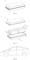
- Fig. 1 shows a secondary battery 5 with a square structure as an example.
- the outer package may include a housing 51 and a cover plate 53.
- the housing 51 may comprise a bottom plate and side plates connected to the bottom plate, and the bottom plate and the side plates enclose to form an accommodating cavity.
- the housing 51 has an opening in communication with the accommodating cavity, and the cover plate 53 can cover the opening to close the accommodating cavity.
- the positive electrode plate, the negative electrode plate, and the separator may be subjected to a winding process or a laminating process to form an electrode assembly 52.
- the electrode assembly 52 is packaged in the accommodating cavity.
- the electrolyte solution infiltrates the electrode assembly 52.
- the number of the electrode assemblies 52 contained in the secondary battery 5 may be one or more, and can be selected by those skilled in the art according to actual requirements.
- the secondary battery can be assembled into a battery module, and the number of the secondary batteries contained in the battery module may be one or more, and the specific number can be selected by those skilled in the art according to the application and capacity of the battery module.
- Fig. 3 shows a battery module 4 as an example.
- a plurality of secondary batteries 5 may be arranged in sequence in the length direction of the battery module 4.
- the secondary batteries may also be arranged in any other manner.
- the plurality of secondary batteries 5 may be fixed by fasteners.
- the battery module 4 may further comprise an outer housing with an accommodating space, and the plurality of secondary batteries 5 are accommodated in the accommodating space.
- the above battery module may also be assembled into a battery pack, the number of the battery modules contained in the battery pack may be one or more, and the specific number can be selected by those skilled in the art according to the application and capacity of the battery pack.
- the battery pack 1 may comprise a battery box and a plurality of battery modules 4 provided in the battery box.
- the battery box comprises an upper box body 2 and a lower box body 3, wherein the upper box body 2 may cover the lower box body 3 to form a closed space for accommodating the battery modules 4.
- the plurality of the battery modules 4 may be arranged in the battery box in any manner.
- the present application further provides a power consuming device.
- the power consuming device comprises at least one of the secondary battery, battery module, or battery pack provided by the present application.
- the secondary battery, the battery module or the battery pack may be used as a power supply or an energy storage unit of the power consuming device.
- the power consuming device may include a mobile device (e.g., a mobile phone, a laptop computer, etc.), an electric vehicle (e.g., a pure electric vehicle, a hybrid electric vehicle, a plug-in hybrid electric vehicle, an electric bicycle, an electric scooter, an electric golf cart, an electric truck), an electric train, ship, and satellite, an energy storage system, and the like, but is not limited thereto.
- the secondary battery, battery module or battery pack can be selected according to the usage requirements thereof.
- Fig. 6 shows a power consuming device as an example.
- the power consuming device may be a pure electric vehicle, a hybrid electric vehicle, a plug-in hybrid electric vehicle, etc.
- a battery pack or a battery module may be used.
- Table 2 Test results of Examples 1 to 33 and Comparative examples 1 to 19 New number Content of coating layer substance (wt%) First-cycle charge gram capacity (mAh/g) Resistivity of powder ( ⁇ •cm) Water content (ppm) Dv50 ( ⁇ m) Stability test Test of integrity and compactness of coating layer Weight growth rate Results of integrity and compactness of coating layer a value b value Mass ratio of coated lithium-rich metal oxide material to solvent Stirring time (min) Stirring rotation speed (rpm) d value (ppm) Results of integrity and compactness of coating layer Example 1 5.0 682 0.534 100 6 0.45% Excellent 5 0% 1 : 50 3 600 1316 Good Example 2 7.0 663 1.433 100 6 0.36% Excellent 5 0% 1 : 50 3 600 1122 Good Example 3 10.0 624 3.239 100 6 0.28% Excellent 5 0% 1 : 50 3 600 926 Good Example 4 5.0 678 0.762 200 6 0.47% Excellent 5 0% 1 : 50 3 600 1425 Good Example 5 5.0
Landscapes
- Chemical & Material Sciences (AREA)
- Chemical Kinetics & Catalysis (AREA)
- Electrochemistry (AREA)
- General Chemical & Material Sciences (AREA)
- Engineering & Computer Science (AREA)
- Manufacturing & Machinery (AREA)
- Composite Materials (AREA)
- Inorganic Chemistry (AREA)
- Battery Electrode And Active Subsutance (AREA)
Applications Claiming Priority (1)
| Application Number | Priority Date | Filing Date | Title |
|---|---|---|---|
| PCT/CN2022/130329 WO2024098198A1 (zh) | 2022-11-07 | 2022-11-07 | 包覆型富锂金属氧化物材料及制备方法、测定包覆型富锂金属氧化物材料中包覆层的方法、正极极片、电池及用电装置 |
Publications (2)
| Publication Number | Publication Date |
|---|---|
| EP4478456A1 true EP4478456A1 (de) | 2024-12-18 |
| EP4478456A4 EP4478456A4 (de) | 2025-10-22 |
Family
ID=91031722
Family Applications (1)
| Application Number | Title | Priority Date | Filing Date |
|---|---|---|---|
| EP22964677.3A Pending EP4478456A4 (de) | 2022-11-07 | 2022-11-07 | Beschichtetes lithiumreiches metalloxidmaterial, herstellungsverfahren dafür, bestimmungsverfahren für beschichtung |
Country Status (4)
| Country | Link |
|---|---|
| US (1) | US20250023031A1 (de) |
| EP (1) | EP4478456A4 (de) |
| CN (1) | CN119256405B (de) |
| WO (1) | WO2024098198A1 (de) |
Families Citing this family (2)
| Publication number | Priority date | Publication date | Assignee | Title |
|---|---|---|---|---|
| CN118465195B (zh) * | 2024-07-09 | 2024-10-18 | 广东瑞浦兰钧能源有限公司 | 电池正极材料表面包覆均匀性的检测方法及应用 |
| CN118825255A (zh) * | 2024-09-18 | 2024-10-22 | 山东创鲁先进电池科技有限公司 | 一种改性富锂锰基氧化物正极材料及其制备方法和应用 |
Family Cites Families (11)
| Publication number | Priority date | Publication date | Assignee | Title |
|---|---|---|---|---|
| US9853323B2 (en) * | 2013-10-31 | 2017-12-26 | Samsung Electronics Co., Ltd. | Positive electrode for lithium-ion secondary battery, and lithium-ion secondary battery |
| US10833321B2 (en) * | 2015-03-06 | 2020-11-10 | Uchicago Argonne, Llc | Cathode materials for lithium ion batteries |
| CN105958034A (zh) * | 2016-07-06 | 2016-09-21 | 福建师范大学 | 包覆硅氧化物的尖晶石富锂锰酸锂材料的制备方法 |
| CN111725576B (zh) * | 2020-07-09 | 2024-04-09 | 湖北融通高科先进材料集团股份有限公司 | 一种碳包覆富锂氧化物复合材料及其制备方法 |
| CN113078316B (zh) * | 2021-03-23 | 2022-04-12 | 电子科技大学 | 钼酸锂包覆的富锂锰基正极材料及其制备方法和应用 |
| CN115215376B (zh) * | 2021-10-29 | 2023-11-03 | 深圳市德方创域新能源科技有限公司 | 正极补锂添加剂及其制备方法与应用 |
| CN114079086A (zh) * | 2021-11-16 | 2022-02-22 | 远景动力技术(江苏)有限公司 | 正极补锂添加剂、正极极片、其制备方法及锂离子电池 |
| CN115295795B (zh) * | 2021-12-24 | 2025-07-18 | 深圳市德方创域新能源科技有限公司 | 正极补锂添加剂及其制备方法和应用 |
| CN114956193B (zh) * | 2022-06-30 | 2024-01-05 | 广东邦普循环科技有限公司 | 一种正极活性材料的制备方法及其应用 |
| CN115172700A (zh) * | 2022-07-20 | 2022-10-11 | 广东邦普循环科技有限公司 | 一种核壳结构富锂氧化物及制备方法和应用 |
| CN118202504A (zh) * | 2022-10-14 | 2024-06-14 | 宁德时代新能源科技股份有限公司 | 正极补锂材料及制备方法、正极片、二次电池和用电装置 |
-
2022
- 2022-11-07 EP EP22964677.3A patent/EP4478456A4/de active Pending
- 2022-11-07 WO PCT/CN2022/130329 patent/WO2024098198A1/zh not_active Ceased
- 2022-11-07 CN CN202280096509.3A patent/CN119256405B/zh active Active
-
2024
- 2024-09-30 US US18/900,956 patent/US20250023031A1/en active Pending
Also Published As
| Publication number | Publication date |
|---|---|
| US20250023031A1 (en) | 2025-01-16 |
| CN119256405B (zh) | 2026-02-03 |
| EP4478456A4 (de) | 2025-10-22 |
| CN119256405A (zh) | 2025-01-03 |
| WO2024098198A1 (zh) | 2024-05-16 |
Similar Documents
| Publication | Publication Date | Title |
|---|---|---|
| CN116636047B (zh) | 高镍正极活性材料、其制备方法、包括其的锂离子电池、电池模块、电池包和用电装置 | |
| KR102909157B1 (ko) | 전기화학 디바이스 및 전자 디바이스 | |
| US20250023031A1 (en) | Coated lithium-rich metal oxide material and preparation method therefor, method for testing coating layer in coated lithium-rich metal oxide material, positive electrode plate, battery and power consuming device | |
| EP4510230A1 (de) | Positivelektrodenaktivmaterial, herstellungsverfahren dafür, sekundärbatterie und elektrische vorrichtung | |
| US20250105266A1 (en) | Negative electrode active material and preparation method thereof, secondary battery, and electrical device | |
| US20240194889A1 (en) | Negative electrode plate and preparation method therefor, secondary battery, battery module, battery pack and power consuming devic | |
| KR20250006952A (ko) | 이차 배터리 및 이를 포함하는 배터리 모듈, 배터리 팩 및 전기 장치 | |
| US20230163284A1 (en) | Modified silicon material and preparation method thereof, negative electrode material | |
| CN117941101B (zh) | 正极活性材料及其制备方法、极片、二次电池及用电装置 | |
| EP4216317A1 (de) | Negativelektrodenaktivmaterial und herstellungsverfahren dafür, sekundärbatterie, batteriemodul, batteriepack und elektrische vorrichtung | |
| EP3926715A1 (de) | Silizium-sauerstoffverbindung, verfahren zu ihrer herstellung und sekundärbatterie, batteriemodul, batteriepack und dazugehöriges gerät | |
| WO2025112502A1 (zh) | 负极极片、二次电池以及用电装置 | |
| EP4682979A1 (de) | Verfahren zur herstellung eines positivelektrodenmaterials, positivelektrodenmaterial, positivelektrodenfolie, batterie und elektrische vorrichtung | |
| EP4329017A1 (de) | Herstellungsverfahren für vorlithiierten positivelektrodenstromkollektor sowie positivelektrodenstromkollektor und lithium-ionen-batterie | |
| EP4087004B1 (de) | Elektrolyt, sekundärbatterie, batteriemodul, batteriepack und vorrichtung | |
| CN121546040A (zh) | 负极活性材料、负极极片、锂离子电池及用电装置 | |
| EP4243144A1 (de) | Sekundärbatterie | |
| CN120637465B (zh) | 一种正极活性材料、电池单体、电池装置及用电装置 | |
| CN115842203B (zh) | 电池构件的防护方法、二次电池、电池模块、电池包和用电装置 | |
| EP4629313A1 (de) | Negativelektrodenfolie, sekundärbatterie und elektrische vorrichtung | |
| US20250273676A1 (en) | Silicon-based negative electrode active material and preparation method therefor, secondary battery, and power consuming apparatus | |
| EP4571884A1 (de) | Lithium-mangan-haltiges spinell-verbundoxid und herstellungsverfahren dafür, positivelektrodenfolie, sekundärbatterie und elektrische vorrichtung | |
| KR20260058892A (ko) | 음극 활물질, 이의 제조 방법, 이차 전지 및 전기 장치 | |
| JP2026500488A (ja) | 正極極板及びその製造方法、電極アセンブリ、電池セル、電池と電力消費装置 | |
| CN122000407A (zh) | 一种二次电池及其制备方法、用电装置 |
Legal Events
| Date | Code | Title | Description |
|---|---|---|---|
| STAA | Information on the status of an ep patent application or granted ep patent |
Free format text: STATUS: THE INTERNATIONAL PUBLICATION HAS BEEN MADE |
|
| PUAI | Public reference made under article 153(3) epc to a published international application that has entered the european phase |
Free format text: ORIGINAL CODE: 0009012 |
|
| STAA | Information on the status of an ep patent application or granted ep patent |
Free format text: STATUS: REQUEST FOR EXAMINATION WAS MADE |
|
| 17P | Request for examination filed |
Effective date: 20240909 |
|
| AK | Designated contracting states |
Kind code of ref document: A1 Designated state(s): AL AT BE BG CH CY CZ DE DK EE ES FI FR GB GR HR HU IE IS IT LI LT LU LV MC ME MK MT NL NO PL PT RO RS SE SI SK SM TR |
|
| RAP1 | Party data changed (applicant data changed or rights of an application transferred) |
Owner name: CONTEMPORARY AMPEREX TECHNOLOGY(HONG KONG) LIMITED |
|
| A4 | Supplementary search report drawn up and despatched |
Effective date: 20250918 |
|
| RIC1 | Information provided on ipc code assigned before grant |
Ipc: H01M 4/485 20100101AFI20250912BHEP Ipc: H01M 4/525 20100101ALI20250912BHEP Ipc: H01M 4/04 20060101ALI20250912BHEP Ipc: H01M 4/505 20100101ALI20250912BHEP Ipc: H01M 4/62 20060101ALI20250912BHEP Ipc: H01M 10/052 20100101ALI20250912BHEP Ipc: H01M 4/36 20060101ALI20250912BHEP Ipc: H01M 4/02 20060101ALN20250912BHEP |
|
| DAV | Request for validation of the european patent (deleted) | ||
| DAX | Request for extension of the european patent (deleted) |