EP4478548A1 - Kontaktklemme für einen verbinder und verfahren zu ihrer herstellung - Google Patents
Kontaktklemme für einen verbinder und verfahren zu ihrer herstellung Download PDFInfo
- Publication number
- EP4478548A1 EP4478548A1 EP23178703.7A EP23178703A EP4478548A1 EP 4478548 A1 EP4478548 A1 EP 4478548A1 EP 23178703 A EP23178703 A EP 23178703A EP 4478548 A1 EP4478548 A1 EP 4478548A1
- Authority
- EP
- European Patent Office
- Prior art keywords
- crimping
- edge
- terminal
- contact
- area
- Prior art date
- Legal status (The legal status is an assumption and is not a legal conclusion. Google has not performed a legal analysis and makes no representation as to the accuracy of the status listed.)
- Pending
Links
Images


Classifications
-
- H—ELECTRICITY
- H01—ELECTRIC ELEMENTS
- H01R—ELECTRICALLY-CONDUCTIVE CONNECTIONS; STRUCTURAL ASSOCIATIONS OF A PLURALITY OF MUTUALLY-INSULATED ELECTRICAL CONNECTING ELEMENTS; COUPLING DEVICES; CURRENT COLLECTORS
- H01R11/00—Individual connecting elements providing two or more spaced connecting locations for conductive members which are, or may be, thereby interconnected, e.g. end pieces for wires or cables supported by the wire or cable and having means for facilitating electrical connection to some other wire, terminal, or conductive member, blocks of binding posts
- H01R11/03—Individual connecting elements providing two or more spaced connecting locations for conductive members which are, or may be, thereby interconnected, e.g. end pieces for wires or cables supported by the wire or cable and having means for facilitating electrical connection to some other wire, terminal, or conductive member, blocks of binding posts characterised by the relationship between the connecting locations
- H01R11/05—Individual connecting elements providing two or more spaced connecting locations for conductive members which are, or may be, thereby interconnected, e.g. end pieces for wires or cables supported by the wire or cable and having means for facilitating electrical connection to some other wire, terminal, or conductive member, blocks of binding posts characterised by the relationship between the connecting locations the connecting locations having different types of direct connections
-
- H—ELECTRICITY
- H01—ELECTRIC ELEMENTS
- H01R—ELECTRICALLY-CONDUCTIVE CONNECTIONS; STRUCTURAL ASSOCIATIONS OF A PLURALITY OF MUTUALLY-INSULATED ELECTRICAL CONNECTING ELEMENTS; COUPLING DEVICES; CURRENT COLLECTORS
- H01R4/00—Electrically-conductive connections between two or more conductive members in direct contact, i.e. touching one another; Means for effecting or maintaining such contact; Electrically-conductive connections having two or more spaced connecting locations for conductors and using contact members penetrating insulation
- H01R4/10—Electrically-conductive connections between two or more conductive members in direct contact, i.e. touching one another; Means for effecting or maintaining such contact; Electrically-conductive connections having two or more spaced connecting locations for conductors and using contact members penetrating insulation effected solely by twisting, wrapping, bending, crimping, or other permanent deformation
- H01R4/18—Electrically-conductive connections between two or more conductive members in direct contact, i.e. touching one another; Means for effecting or maintaining such contact; Electrically-conductive connections having two or more spaced connecting locations for conductors and using contact members penetrating insulation effected solely by twisting, wrapping, bending, crimping, or other permanent deformation by crimping
- H01R4/20—Electrically-conductive connections between two or more conductive members in direct contact, i.e. touching one another; Means for effecting or maintaining such contact; Electrically-conductive connections having two or more spaced connecting locations for conductors and using contact members penetrating insulation effected solely by twisting, wrapping, bending, crimping, or other permanent deformation by crimping using a crimping sleeve
-
- H—ELECTRICITY
- H01—ELECTRIC ELEMENTS
- H01R—ELECTRICALLY-CONDUCTIVE CONNECTIONS; STRUCTURAL ASSOCIATIONS OF A PLURALITY OF MUTUALLY-INSULATED ELECTRICAL CONNECTING ELEMENTS; COUPLING DEVICES; CURRENT COLLECTORS
- H01R43/00—Apparatus or processes specially adapted for manufacturing, assembling, maintaining, or repairing of line connectors or current collectors or for joining electric conductors
- H01R43/16—Apparatus or processes specially adapted for manufacturing, assembling, maintaining, or repairing of line connectors or current collectors or for joining electric conductors for manufacturing contact members, e.g. by punching and by bending
-
- H—ELECTRICITY
- H01—ELECTRIC ELEMENTS
- H01R—ELECTRICALLY-CONDUCTIVE CONNECTIONS; STRUCTURAL ASSOCIATIONS OF A PLURALITY OF MUTUALLY-INSULATED ELECTRICAL CONNECTING ELEMENTS; COUPLING DEVICES; CURRENT COLLECTORS
- H01R13/00—Details of coupling devices of the kinds covered by groups H01R12/70 or H01R24/00 - H01R33/00
- H01R13/02—Contact members
- H01R13/04—Pins or blades for co-operation with sockets
- H01R13/08—Resiliently-mounted rigid pins or blades
-
- H—ELECTRICITY
- H01—ELECTRIC ELEMENTS
- H01R—ELECTRICALLY-CONDUCTIVE CONNECTIONS; STRUCTURAL ASSOCIATIONS OF A PLURALITY OF MUTUALLY-INSULATED ELECTRICAL CONNECTING ELEMENTS; COUPLING DEVICES; CURRENT COLLECTORS
- H01R4/00—Electrically-conductive connections between two or more conductive members in direct contact, i.e. touching one another; Means for effecting or maintaining such contact; Electrically-conductive connections having two or more spaced connecting locations for conductors and using contact members penetrating insulation
- H01R4/10—Electrically-conductive connections between two or more conductive members in direct contact, i.e. touching one another; Means for effecting or maintaining such contact; Electrically-conductive connections having two or more spaced connecting locations for conductors and using contact members penetrating insulation effected solely by twisting, wrapping, bending, crimping, or other permanent deformation
- H01R4/18—Electrically-conductive connections between two or more conductive members in direct contact, i.e. touching one another; Means for effecting or maintaining such contact; Electrically-conductive connections having two or more spaced connecting locations for conductors and using contact members penetrating insulation effected solely by twisting, wrapping, bending, crimping, or other permanent deformation by crimping
- H01R4/20—Electrically-conductive connections between two or more conductive members in direct contact, i.e. touching one another; Means for effecting or maintaining such contact; Electrically-conductive connections having two or more spaced connecting locations for conductors and using contact members penetrating insulation effected solely by twisting, wrapping, bending, crimping, or other permanent deformation by crimping using a crimping sleeve
- H01R4/203—Electrically-conductive connections between two or more conductive members in direct contact, i.e. touching one another; Means for effecting or maintaining such contact; Electrically-conductive connections having two or more spaced connecting locations for conductors and using contact members penetrating insulation effected solely by twisting, wrapping, bending, crimping, or other permanent deformation by crimping using a crimping sleeve having an uneven wire-receiving surface to improve the contact
Definitions
- the present disclosure relates to a terminal for electric contact, possibly for incorporating within a connector, intended to be crimped by an EMPT process, for "electromagnetic pulse technology".
- the terminal comprises a contact portion and a crimping portion which includes a crimping area.
- a conductive material surrounds a crimping cavity along an electrically closed perimeter.
- said crimping area is made from a stamped metal sheet bent on itself, two opposite edges of which are assembled together in an electrically conductive manner.
- Conductive assembly may be done edge to edge, with its edges fixed together by a puzzle-type assembly, or welding line or point, or both.
- crimping and contact areas are integral together and made from a same metal sheet, for example by stamping and/or rolling.
- Disclosure also relates to a method for manufacturing such a terminal.
- the disclosure relates to the field of connectors, and in particular to the field of automotive connectors.
- Connectors are used to assemble several previously manufactured devices, usually two, in order to make a connection between them that allows electrical energy and/or signals to be transmitted between these devices.
- These devices can each be a cable or a motor, or another type of device such as a computer or a sensor or a lighting device.
- a connector has one or more contact terminals, each of which is intended to make electrical contact with a counter terminal within a counter connector when the latter is mated with the connector.
- Such a connector can be a multi-contact connector, comprising several different contact terminals insulated from each other.
- a single terminal can also be used alone, insulated or not from the outside, and seen as a mono-contact conductor.
- Such a contact terminal generally has a contact portion, intended to come into electrical contact with the contact portion of the counter-terminal; and a connection portion intended to be permanently connected with one or more electrical conductors such as wires within a cable.
- This connection is usually made either by soldering or brazing or by crimping.
- Crimping is a widely used method, and has the advantage of being quick and simple, and to be done at ambient temperature. Such crimping is obtained by plastic deformation of the crimping portion so as for it to be tightly clamped and pressed around the conductors. The conductors are inserted into a cavity formed within the crimping portion, which is placed in a press, usually between a die and a tool. Electrical contact is then most often made by simply pressing the crimping portion against the exposed surface of the conductor(s).
- an electromagnetic pulse crimping process for Electro Magnetic Pulse Technology. This comprises subjecting the crimping portion and the conductors to a very short pulse of a very strong magnetic field, typically longitudinally to the conductors, so as to generate a circular current in the crimping portion all around the conductors.
- This circular current associated with the magnetic field that is transverse to it, produces a force in a third direction perpendicular to the other two, in accordance with Lorentz's law. This force is directed towards the interior of the cable, all around it, and crushes the crimping portion on the conductors within the cable.
- EMPT technology is very efficient and relatively fast to operate, but it creates particular constraints for the design of the crimping portion.
- the crimping portion must be electrically conductive all the way around the conductors.
- the contact terminals currently in use have a crimping portion in the form of a circular skirt, usually machined by material removal.
- EP4099519A1 discloses a sleeve-like crimping portion which could be compatible with EMPT crimping, though using such technology is not disclosed nor suggested within its teaching.
- Fig.1 shows a perspective view of a longitudinal section of a female terminal 9 according to EP4099519A1 .
- This terminal 9 has a connection portion 92, configured for electrically connecting, by crimping and/or soldering, the terminal to an electrical cable.
- This connection portion 92 is in shape of a circular skirt longitudinal to the terminal, in the opening 920 of which the cable is to be longitudinally inserted.
- Integral with the connection portion, and longitudinal with it, the terminal has a contact portion 93 intended to be mated, by an insertion movement along an axial direction D9, with the contact portion of a counter terminal not represented here.
- the contact portion 93 has several flexible blades 931, the internal surface 9310 of it is intended to make electrical contact with an external surface of the counter connector. In its center, contact portion 93 has a finger 932 the external surface 9320 of which is to make electrical contact of an internal surface of the counter connector.
- connection portion 92 may possibly be manufactured by machining and/or casting, but not by stamping nor rolling a metal sheet.
- Fig.2 illustrates the basic principle of EMPT crimping of a terminal, such as terminal 9 from Fig.1 , around wires 929 of an electrical cable.
- the skirt 92 of the connection portion is provided with its wires 929 and is inserted within an electrical loop L.
- a current Is passes in the conductors of the loop L, thus generating a magnetic field B which is longitudinal to the skirt 92.
- the skirt has electrical continuity all around its internal opening 920, it forms a conductive closed loop where the magnetic field B produces an electrical current Ir.
- skirt current Ir interacts with the magnetic field B perpendicular to it, for producing a force F which is perpendicular to both current Ir and field B and is center-oriented.
- this centripetal force F is sufficient to crush the skirt 92 on and around the wires 929 and thus produce the crimping.
- Fig.3 to Fig.6 are illustrated various examples of embodiments of a terminal according to the present disclosure. While these examples have the same kinds of contact portion, it must be understood that the disclosure mainly pertains to the connection portion. Different kinds of contact portions may be configured with such connection portion, in particular many contact portions of a known type.
- the crimping portion includes a crimping area 2 where an electrically conductive material surrounds, along an electrically closed perimeter C2, a crimping cavity 20 arranged for receiving one or several electrical conductors the terminal 11 to 15 is to be crimped on.
- manufacturing this crimping area comprises the following steps :
- Fig.3 is illustrated a first example of embodiment of the disclosure, with a terminal 11. Its contact portion 3 has the same kind of central finger 32 (not visible here) and blades 39 as the terminal 9 of Fig.1 .
- the terminal 11 of the disclosure has a connection portion, here called the crimping portion 2, intended to be EMPT-crimped on a cable.
- This crimping portion 2 is in shape of a circular cylindrical skirt of axis A1, with a blind back opening 20 for inserting the cable to be connected with the terminal.
- This skirt also called barrel, is made from a metal sheet. The sheet is stamped for making its external shape, and bent by stamping or rolling so as to have a shape of a cylinder.
- Its crimping area edges 211, 212 are joined together in an edge to edge manner, by assembly 213 of two complementary shapes 2131, 2130 of respective said edges in a way similar to assembling two pieces of a puzzle, in a manner which is known per se.
- the first edge 211 has a protrusion 2131 the width of which increases in the direction of the second edge 212, and which is arranged to be inserted in an edge-to-edge contact cooperation within a cavity 2130 formed in the second edge, which cavity has a width which decreases in the direction of the first edge, thus producing an assembling 213 here called "puzzle" assembly.
- a protrusion 2131 the width of which increases in the direction of the second edge 212
- which cavity has a width which decreases in the direction of the first edge
- the contact portion 3 may be produced out of the same sheet blank, or produced separately and assembled for example in a known manner.
- Fig.4 shows a second example of embodiment, which will be described only in its differences.
- the terminal 12 has a crimping portion 2 similar to terminal 11 of Fig.3 .
- the contact portion 3 is here also made of a metal sheet blank which is bent into a barrel, the edges 311, 312 of which are here also joined by an edge to edge puzzle assembly 313.
- contact portion 3 is a barrel 391 which is made from the same blank as crimping portion 2, though its diameter may be different thanks to stamping or other plastic deformation operations that are known per se.
- Center finger 321 may be produced as a separate part, which is here inserted into one 33 or another 32 barrel, and fixed therein by a hook that clips in a see-through opening 303 of such barrel.
- Fig.5 shows a third example of embodiment, which will be described only in its differences with Fig.4 .
- crimping area 2 has its first 211 and second 212 edges assembled by one or several soldering or welding lines, in particular one line 214, making them connected in an electrically conductive manner.
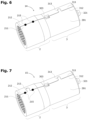
- Fig.6 shows a fourth example of embodiment, which will be described only in its differences with Fig.4 .
- crimping area 2 has its first 211 and second 212 edges are assembled with one or several soldering or welding points, in particular two points 215.
- Fig.7 shows a fifth example of embodiment, which will be described only in its differences with Fig.4 .
- crimping area 2 has its first 211 and second 212 edges assembled both by a combination of puzzle assemblies and soldering or welding lines or points, in particular one puzzle assembly 213 and two points 215.
Landscapes
- Engineering & Computer Science (AREA)
- Manufacturing & Machinery (AREA)
- Connections Effected By Soldering, Adhesion, Or Permanent Deformation (AREA)
Priority Applications (1)
| Application Number | Priority Date | Filing Date | Title |
|---|---|---|---|
| EP23178703.7A EP4478548A1 (de) | 2023-06-12 | 2023-06-12 | Kontaktklemme für einen verbinder und verfahren zu ihrer herstellung |
Applications Claiming Priority (1)
| Application Number | Priority Date | Filing Date | Title |
|---|---|---|---|
| EP23178703.7A EP4478548A1 (de) | 2023-06-12 | 2023-06-12 | Kontaktklemme für einen verbinder und verfahren zu ihrer herstellung |
Publications (1)
| Publication Number | Publication Date |
|---|---|
| EP4478548A1 true EP4478548A1 (de) | 2024-12-18 |
Family
ID=86760406
Family Applications (1)
| Application Number | Title | Priority Date | Filing Date |
|---|---|---|---|
| EP23178703.7A Pending EP4478548A1 (de) | 2023-06-12 | 2023-06-12 | Kontaktklemme für einen verbinder und verfahren zu ihrer herstellung |
Country Status (1)
| Country | Link |
|---|---|
| EP (1) | EP4478548A1 (de) |
Citations (4)
| Publication number | Priority date | Publication date | Assignee | Title |
|---|---|---|---|---|
| DE102011017071A1 (de) * | 2011-04-14 | 2012-10-18 | Auto-Kabel Managementgesellschaft Mbh | Anschlussteil für elektrische Anlagen |
| EP2871718A1 (de) * | 2012-07-09 | 2015-05-13 | Furukawa Electric Co., Ltd. | Druckfixierbarer anschluss, verbindungsstruktur und verbinder |
| US20150364837A1 (en) * | 2013-02-22 | 2015-12-17 | Furukawa Electric Co., Ltd. | Method for Manufacturing Crimp Terminal, Crimp Terminal, and Wire Harness |
| EP4099519A1 (de) | 2021-06-01 | 2022-12-07 | Aptiv Technologies Limited | Stecker- und buchsenstromanschlussanordnung, buchen- und steckerstromanschluss |
-
2023
- 2023-06-12 EP EP23178703.7A patent/EP4478548A1/de active Pending
Patent Citations (4)
| Publication number | Priority date | Publication date | Assignee | Title |
|---|---|---|---|---|
| DE102011017071A1 (de) * | 2011-04-14 | 2012-10-18 | Auto-Kabel Managementgesellschaft Mbh | Anschlussteil für elektrische Anlagen |
| EP2871718A1 (de) * | 2012-07-09 | 2015-05-13 | Furukawa Electric Co., Ltd. | Druckfixierbarer anschluss, verbindungsstruktur und verbinder |
| US20150364837A1 (en) * | 2013-02-22 | 2015-12-17 | Furukawa Electric Co., Ltd. | Method for Manufacturing Crimp Terminal, Crimp Terminal, and Wire Harness |
| EP4099519A1 (de) | 2021-06-01 | 2022-12-07 | Aptiv Technologies Limited | Stecker- und buchsenstromanschlussanordnung, buchen- und steckerstromanschluss |
Similar Documents
| Publication | Publication Date | Title |
|---|---|---|
| EP2556565B1 (de) | Elektromagnetische abschirmungsvorrichtung | |
| EP2335326B1 (de) | Elektrischer kontakt, menge elektrischer kontakte, produkt und baugruppe mit einem solchen elektrischen kontakt und verfahren zur herstellung und verfahren zur elektrischen verbindung | |
| JP2018026323A (ja) | 無線周波数同軸コネクタアセンブリおよび当該アセンブリの製造方法 | |
| US20180090900A1 (en) | Method for manufacturing female terminal and female terminal | |
| WO1998020581A1 (en) | Insulated wire with integral terminals | |
| EP2606536B1 (de) | Elektrische steckerklemme | |
| US11942737B2 (en) | Joint connector | |
| WO2014129227A1 (ja) | 接続構造体の製造方法、接続構造体、ワイヤーハーネス、圧着部材、及び圧着装置 | |
| EP4075610A1 (de) | Stecker oder buchse für kraftfahrzeuganwendungen und verfahren zur montage davon | |
| JP2516089B2 (ja) | コネクタの結線構造とその方法 | |
| EP1533868A2 (de) | Druckverbindungsanordnung für Koaxialkabel | |
| US11616316B2 (en) | Socket contact element for an electrically conductive connection | |
| US5120241A (en) | Miniature electrical connector | |
| US5171166A (en) | Miniature electrical contact terminal | |
| US8272901B2 (en) | Crimp contacts and electrical connector assemblies including the same | |
| JP4977768B2 (ja) | 複数種の端子金具の製造方法 | |
| JP5146759B2 (ja) | 端子金具、端子金具付き電線、及び端子金具付き電線の製造方法 | |
| JPH0641082U (ja) | 同軸コネクタ | |
| JP3024946U (ja) | 電気コネクタのターミナル | |
| US4626061A (en) | Crimp connect terminals | |
| US11710911B2 (en) | Terminal with a wire connecting portion having a sandwiching portion | |
| US20090170366A1 (en) | Shield sleeve for a plug connector | |
| CN224191255U (zh) | 一种汽车射频连接器端子 | |
| JP2006236873A (ja) | 端子金具の製造方法及び該端子金具 | |
| EP4002591B1 (de) | Leistungsklemme mit verbessertem crimp-abschnitt und crimpverfahren dafür |
Legal Events
| Date | Code | Title | Description |
|---|---|---|---|
| PUAI | Public reference made under article 153(3) epc to a published international application that has entered the european phase |
Free format text: ORIGINAL CODE: 0009012 |
|
| STAA | Information on the status of an ep patent application or granted ep patent |
Free format text: STATUS: THE APPLICATION HAS BEEN PUBLISHED |
|
| AK | Designated contracting states |
Kind code of ref document: A1 Designated state(s): AL AT BE BG CH CY CZ DE DK EE ES FI FR GB GR HR HU IE IS IT LI LT LU LV MC ME MK MT NL NO PL PT RO RS SE SI SK SM TR |
|
| STAA | Information on the status of an ep patent application or granted ep patent |
Free format text: STATUS: REQUEST FOR EXAMINATION WAS MADE |
|
| 17P | Request for examination filed |
Effective date: 20250617 |