EP4478575A1 - Procédé et système de commande de convertisseurs electroniques - Google Patents
Procédé et système de commande de convertisseurs electroniques Download PDFInfo
- Publication number
- EP4478575A1 EP4478575A1 EP22709336.6A EP22709336A EP4478575A1 EP 4478575 A1 EP4478575 A1 EP 4478575A1 EP 22709336 A EP22709336 A EP 22709336A EP 4478575 A1 EP4478575 A1 EP 4478575A1
- Authority
- EP
- European Patent Office
- Prior art keywords
- voltage
- electronic converter
- load angle
- converter
- droop
- Prior art date
- Legal status (The legal status is an assumption and is not a legal conclusion. Google has not performed a legal analysis and makes no representation as to the accuracy of the status listed.)
- Pending
Links
Images





Classifications
-
- H—ELECTRICITY
- H02—GENERATION; CONVERSION OR DISTRIBUTION OF ELECTRIC POWER
- H02J—ELECTRIC POWER NETWORKS; CIRCUIT ARRANGEMENTS OR SYSTEMS FOR SUPPLYING OR DISTRIBUTING ELECTRIC POWER; SYSTEMS FOR STORING ELECTRIC ENERGY
- H02J3/00—Circuit arrangements for AC mains or AC distribution networks
- H02J3/38—Arrangements for feeding a single network from two or more generators or sources in parallel; Arrangements for feeding already energised networks from additional generators or sources in parallel
- H02J3/46—Controlling the sharing of generated power between the generators, sources or networks
Definitions
- the present invention belongs to the field of electronic converters, whether connected to the electricity grid or to isolated systems. More specifically, the invention relates to methods and systems for controlling electronic converters.
- generation systems photovoltaic, wind, etc.
- storage systems batteries, fuel cells, etc.
- DC to AC electronic converters also called inverters
- the inverters When connected to isolated systems, i.e., to systems not connected to the grid, the inverters are controlled to behave as voltage sources, contributing to the generation and maintenance of the amplitude and frequency of the alternating voltage generated.
- inverters have traditionally been controlled as current sources, following the voltage at the connection point to exchange the desired active and reactive powers with the grid.
- GS synchronous generators
- the increasing penetration of renewable energy sources and storage systems is causing GS to be replaced by generators connected through inverters.
- maintaining control of the inverters as current sources could end up compromising the stability of the grid voltage amplitude and frequency.
- the inverters must be controlled as voltage sources so that they participate in the maintenance of the grid voltage and frequency.
- a widespread method for controlling the amplitude and frequency of the alternating voltage in systems with several inverters connected in parallel working as voltage sources is droop control. This technique makes it possible to guarantee the distribution of active and reactive power between the different generators, according to the capacity thereof, based on the local measurements in each inverter, without requiring communication between them.
- the droop control has parallel control loops, the active power-frequency (P-f) droop and the reactive power-voltage (Q-V) droop, with which the frequency and amplitude of the reference voltage that must be generated by the inverter based on the active and reactive power measurements, respectively, are calculated.
- the P-f droop is responsible for keeping the inverters synchronised and, at the same time, balancing the distribution of active power.
- An example of this method is found in the document: " Zhong, Q. C., & Zeng, Y. Universal droop control of inverters with different types of output impedance. IEEE access, 2016, 4, 702-712 ".
- the operation of the P-f droop causes the steady-state frequency to vary as a function of the power consumed by the loads connected to the system.
- the active power-load angle (P- ⁇ ) droop has been proposed, which directly calculates the difference in angle with the output voltage that the inverter has to generate to exchange the desired active power.
- An example of this method is found in the document: " B. John, A. Ghosh and F. Zare, Load Sharing in Medium Voltage Islanded Microgrids With Advanced Angle Droop Control, in IEEE Transactions on Smart Grid, vol. 9, no. 6, pp. 6461-6469, Nov. 2018 ".
- this technique has the drawbacks of being only valid for isolated systems and requiring fast and precise communication between inverters or the use of GPS synchronisation systems to guarantee the stable behaviour of the system.
- inverters controlled as voltage sources include methods for limiting the current (supplied current) to (or below) the maximum value thereof. In this way, in current limitation, the amplitude of the voltage is not controlled and the voltage droop is deactivated.
- the frequency droop remains active since the inverter must continue imposing the frequency and it thus continues to participate in maintaining the same.
- the output voltage of the inverter decreases, causing the active power to no longer change in the same manner with the overload level of the inverter and may even decrease instead of increase when the overload increases.
- droop control methods based on active power do not present stable behaviour in current limitation and tend to desynchronise the inverters.
- some methods proposed in the state of the art include a support PLL (Phase Locked Loop) to control the frequency in these situations.
- PLL Phase Locked Loop
- An example of this method is found in the document " Shi, K., Song, W., Xu, P., Liu, R., Fang, Z., & Ji, Y. Low-voltage ride-through control strategy for a virtual synchronous generator based on smooth switching. IEEE Access, 2017, 6, 2703-2711 ".
- the use of the support PLL causes the inverters to stop contributing to the maintenance of the system frequency and, in addition, has stability problems in certain line impedance ranges, as reflected in the document " Hu, Qi, et al. Large signal synchronizing instability of PLL-based VSC connected to weak AC grid. IEEE Transactions on Power Systems, 2019, vol. 34, no. 4, p. 3220-3229 ".
- I active -f droop the active current
- This variable is obtained by dividing the active power by the amplitude of the voltage at the inverter output.
- I act -f droop a behaviour similar to that of the P-f droop is achieved under normal operating conditions, and it improves the behaviour in the event of overloads and shallow voltage dips.
- An example of this method is found in the document " Brabandere, K.D., Bolsens, B., Keybus, J.V., et al.: 'A voltage and frequency droop control method for parallel inverters', IEEE Trans.
- the present invention provides a method and a system that aim to solve the drawbacks of the methods and systems described in the state of the art.
- the present invention provides a method and a system for controlling an electronic converter connected to an isolated system (for example, to one or more loads) or to the electricity grid. To perform this control, the method calculates, based on the load angle of the electronic converter or on a load angle-dependent parameter, the frequency of a voltage set-point that must be generated by the electronic converter.
- the method is applicable to electronic converters connected in parallel, whether to isolated systems (for example, loads) or to the electricity grid.
- the electronic converter can be single-phase or three-phase.
- the frequency of the voltage set-point is based on the droop concept.
- the frequency of the voltage set-point is determined by applying a frequency droop control using the load angle (or a load angle-dependent parameter) directly as input variable, which is the phase shift between the voltage imposed by the electronic converter before the output filter and the voltage at the filter output, instead of using the active power or active current, as is performed in the state of the art.
- This variable represents the phase shift between the electronic converter and the system (the electricity grid and/or isolated systems), both under normal conditions, wherein the voltages present values close to the rated (nominal) value, and in the presence of excess loads, voltage dips or short circuits, wherein the amplitude of the voltages decreases, for example, due to the actuation of a current limiting method.
- the method and system are applicable, among others, to DC/AC (Direct Current/Alternating Current) electronic converters or to DC/DC + DC/AC electronic converters.
- DC/AC Direct Current/Alternating Current
- the converters can be connected in parallel with the electricity grid or to a system of loads isolated from the grid, either independently or with several converters in parallel.
- the proposed control method is especially applicable in inverters controlled as a voltage source.
- the method can be applied, among others, to inverters controlled as a voltage source that also implement a current limiting method.
- the proposed control method determines the frequency of the voltage or voltages (voltage set-point) that the electronic converter must impose from the load angle ( ⁇ ) or a variant of the same, using a load angle - frequency droop ( ⁇ -f droop).
- ⁇ -f droop load angle - frequency droop
- any of the existing methods of the state of the art can be used. In this way, the electronic converter is controlled at the output thereof as an alternating voltage source.
- a method for controlling an electronic converter comprises the steps of: for each of the phases of the electronic converter, measuring an instantaneous current and an instantaneous voltage of the electronic converter; calculating, from the current measurements and voltage measurements: an active power exchanged by the electronic converter and an effective value of voltage of the electronic converter; and calculating an effective value of voltage imposed by the conversion step of the electronic converter.
- the method further comprises: obtaining the load angle or a load angle-dependent parameter from the active power, the effective value of voltage and the effective value of imposed voltage; calculating the frequency of a voltage set-point that must be generated by the electronic converter from the load angle or on the load angle-dependent parameter; obtaining the voltage set-point that must be generated by the electronic converter from the calculated frequency.
- the method calculates the frequency of the voltage set-point that must be generated by the electronic converter from the load angle of the electronic converter, or from a load angle-dependent parameter. This variable directly represents the phase shift of each electronic converter with the system regardless of the operating conditions.
- the frequency of the voltage set-point that must be generated by the electronic converter is obtained by applying a frequency droop to the load angle or to the load angle-dependent parameter.
- the load angle or load angle-dependent parameter is filtered before applying the frequency droop.
- the measured voltage has been measured at the terminals of a capacitor of an output filter of each phase of the electronic converter.
- the measured voltage has been measured at the output of the electronic converter.
- the measured voltage has been obtained by measuring the line voltage.
- the method further comprises, once the voltage set-point is obtained, applying a voltage control step to determine a voltage that the electronic converter must impose to achieve that voltage set-point.
- the voltage control step may implement, for example, a voltage control in alpha and beta axes, or a voltage control in dq axes, or an open-loop voltage control.
- the method further comprises a complementary current limiting step, which is preferably applied at the output of the voltage control, for which any of the existing methods of the state of the art can be used.
- the method further comprises correcting the load angle or the load angle-dependent parameter, to compensate for the phase shift introduced by the current limitation between the voltage set-point and the voltage imposed by the electronic converter.
- the method is applied to a plurality of electronic converters connected in parallel.
- the method is applied to one or more single-phase electronic converters.
- the method is applied to one or more three-phase electronic converters.
- the method is repeated at moments in time that are marked according to a clock frequency.
- a second aspect of the invention provides a system for controlling an electronic converter to carry out the method according to the first aspect of the invention.
- the control system comprises: means for measuring an instantaneous current and an instantaneous voltage of the electronic converter; means for: calculating, from the current measurements and voltage measurements: an active power exchanged by the electronic converter and an effective value of phase voltage of the electronic converter; calculating an effective value of voltage imposed by the conversion step of the electronic converter; obtaining the load angle or a load angle-dependent parameter from the active power, the effective value of voltage and the effective value of imposed voltage; calculating the frequency of a voltage set-point that must be generated by the electronic converter from the load angle or on the load angle-dependent parameter; and obtaining the voltage set-point that must be imposed on the electronic converter from said frequency.
- control system further comprises a voltage controller.
- control system further comprises a current controller.
- the method and system for controlling electronic converters guarantee that the electronic converters remain synchronised both under normal operating conditions and in the presence of excess loads, voltage dips or short circuits, without requiring the introduction of communication means (input/output interfaces, transmitters/receivers, antennas, etc.) between the electronic converters.
- the method for controlling an electronic converter of the invention is performed in a plurality of time instants. Said time instants relate, in the present description, to each sampling operation according to a frequency, i.e., to clock ticks or pulses.
- the sampling frequency falls within the usual ranges of controllers used in systems for controlling inverters, for example, at the switching frequency of the converter or multiples or sub-multiples thereof. That is, the control method or algorithm is executed periodically.
- the execution period can take a value in the range between 1 and 100,000 ⁇ s (microseconds, 10 -6 seconds), such as a value between 10 and 50,000 ⁇ s, or between 10 and 10,000 ⁇ s, or between 10 and 2,000, or between 50 and 1,200, or between 50 and 200 ⁇ s, or between 80 and 150 ⁇ s. For example, it runs once every 1,000 ⁇ s (1 ms).
- the proposed method has the following advantages:
- the connection diagram shown corresponds to the phase of a single-phase converter.
- the electronic converter 10 n has been schematically represented as two blocks 1, 2.
- Block 1 represents the conversion step, which is conventional and falls outside the scope of the present invention.
- Block 2 represents the output filter, which can be an LCL filter, an LC filter or any other conventional variant.
- the output filter 2 is intended to filter switching harmonics.
- the input 3 of the converter 10 n can be an energy source (for example, a continuous energy source) or a storage system. If it is an energy source, it can be of different types, such as a renewable generation source (photovoltaic solar or wind, for example).
- the output of the converter 10 n is connected to the electricity grid 5 (for example, to the main electricity grid) or to a load 4.
- the electricity grid 5 for example, to the main electricity grid
- a load 4 for example, to the electricity grid
- the converter 10 n specifically, the output step 2
- the load 4 or the electricity grid 5 there may be a transformer, not shown in Figure 1A .
- the electronic converter 10 n may be working in parallel with other electronic converters and/or power generators.
- Figure 1B shows a connection diagram of several electronic converters 10 1 ... 10 n in parallel like the one in Figure 1A .
- the same reference numbers as in Figures 1A-1B have been used to indicate the same elements.
- the input 3 of the converter 10 n can be an energy source (for example, a continuous energy source) or a storage system. If it is an energy source, it can be of different types, such as a renewable generation source (photovoltaic solar or wind, for example).
- the output of the converter 10 n is connected to the electricity grid 5 (for example, to the main electricity grid) or to several loads (for example, one per phase).
- the output filter 2 is an LCL filter, but an LC filter or any other variant could alternatively be used.
- the converter 10 n specifically, the output step 2
- the load(s) 4 or the electricity grid 5 there may be a transformer, not shown in Figure 1C .
- the three-phase electronic converter 10 n of Figure 1C may be working in parallel with other electronic converters and/or power generators. For conciseness, this possibility has not been illustrated, but a skilled person will understand that the connection diagram thereof is similar to that of Figure 1B .
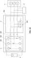
- the method of the invention implements a control of the voltage generated by the electronic converter 10 n .
- the control method is executed at all times and, in the event of several converters 10 1 ... 10 n ( Figure 1B ), in parallel between them. Specifically, the control method is applied to the phase (or phases) of the conversion step 1 of the one or more electronic converters 10 n .
- the output voltage of the converter 10 n (i.e., after the filtering step 2) can be both the voltage measured at the terminals of the capacitor of the output filter 2 (Vc_r,n, V C_s,n , V C_t,n in Figure 1C ), and the voltage in the grid 5 or load (loads) 4, or the voltage measured in the line, as represented in Figures 1A-1B through the voltmeter 6. This is applicable to both single-phase and three-phase converters.
- the control method calculates the voltage set-points that should be generated in each phase (if the converter is three-phase) or in the phase (if the converter is single-phase) by the electronic converter 10 n so that said phase behaves as an alternating voltage source with certain amplitude and frequency values, i.e., those desired depending on the load, the loads or the grid to which the converter is going to be connected.
- Figure 2 shows the single-phase equivalent circuit of the impedance of the filter 2 of each electronic converter 10 n and a phasor representation of currents and voltages.
- the point indicated as “A” in Figure 2 corresponds to the output of the conversion step 1 of a converter 10 n (or input of the filtering step 2)
- the point indicated as "B” in Figure 2 corresponds to the output of the filtering step 2 of a converter 10 n .
- Figure 2 also shows: the effective value of the voltage E n imposed by the conversion step 1 before the filter 2 (for example, in Figure 1C , effective value e r,n between the point 101 and the neutral 104, effective value e s,n between the point 102 and the neutral 104, and effective value e t,n between the point 103 and the neutral 104); the effective value of the current I n of the converter (current i n in Figure 1A , current i 1 , i 2 , ... i n in Figure 1B , current i r,n , i s,n , ... i t,n in Figure 1C ); and the effective value V n of the output voltage of the converter 10 n .
- the effective value of the voltage E n imposed by the conversion step 1 before the filter 2 for example, in Figure 1C , effective value e r,n between the point 101 and the neutral 104, effective value e s,n between the point 102 and the neutral
- the angle ⁇ n is also mentioned, which expresses the phase shift between the current and output voltage of the converter, and the load angle ⁇ n, which represents the phase shift of the voltage of each electronic converter 10 n with that of the system.
- the vector of the voltage imposed by the converter E n with a given loading angle ⁇ n is expressed, compared to the output "B", in which the vector of the output voltage V n is expressed, considering this vector as an angle reference.
- FIG. 2 The lower portion of Figure 2 shows the vectors: voltage imposed E n by the converter 10 before the filter 2 (i.e., at the output of conversion step 1), output voltage of the converter V n and current of the converter I n . It can be seen that the load angle ⁇ n represents the angle between the voltage imposed E n by the conversion step 1 and the output voltage V n .
- a voltage control can be applied to determine the voltage (one per phase, in the case of a three-phase converter) that the converter must impose to achieve that voltage set-point.
- the complete control is schematised as an example in Figure 4 .
- obtaining the frequency of the voltage set-point from a variable that does not depend on the voltage E n imposed by the converter or on the output voltage of the converter V n is proposed.
- obtaining the frequency of the voltage set-point that must be generated by the electronic converter (frequency that is obtained using a method or droop control) from the load angle ⁇ n , or from a parameter dependent on the same, is proposed. This ensures the correct reaction of the electronic converter to changes in any operating mode.
- the load angle ⁇ or a load angle-dependent parameter ⁇ , which represents the phase shift of the electronic converter 10 with the system to which it is connected at the output thereof (i.e., with the electricity grid 5 or the load or loads 4).
- the frequency droop ( ⁇ -f droop) will subsequently be carried out to obtain the frequency of the voltage set-point.
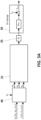
- Figure 3A shows a general block diagram for obtaining the reference frequency for a converter "n".
- the current i n of the converter 10 n current i delivered by conversion step 1
- the output voltage v n of the converter 10 n are measured.
- the current of the converter 10 n has been represented as i n
- Figure 1B it has been represented as i 1 ... i n for the n converters represented
- Figure 1C it has been represented as i r,n , i s,n , i t,n for each of the phases of a three-phase converter.
- the output voltage of the converter 10 n can be, as explained, the voltage measured at the terminals of the capacitor of the output filter 2 (V C_r,n , V C_s,n , V C_t,n in Figure 1C ), or the voltage at the output of the converter as represented in the figures through the voltmeter 6.
- the measured current and voltage have been represented as “i n " and "v n ".
- a first step (block 20), from the measured current and voltage: the active power P n exchanged by the electronic converter 10 n and an effective value of voltage V n at the output of the electronic converter 10 n , are calculated.
- the active power P n exchanged by the electronic converter 10 n and an effective value of voltage V n at the output of the electronic converter 10 n are calculated.
- conventional techniques are used, known to a person of average skill, which fall outside the scope of the present invention.
- an effective value of voltage E n imposed by conversion step 1 is calculated.
- the effective value of imposed voltage E n conventional techniques are used, known to a person of average skill, which fall outside the scope of the present invention.
- the effective value of imposed voltage E n can be obtained from the values applied in a previous cycle of the converter control or, in the event of using a PWM modulation, calculated from the DC voltage (not illustrated) and from the relationship between the modulation and the peak value of the triangle.
- Instantaneous measurements of voltage v n and current i n can be filtered before being used for the various calculations.
- the filter used can be implemented both in an analogue and a digital manner.
- the filter may be high pass, low pass, or a combination of both. This filtering is not illustrated (it is generally included in block 20).
- the load angle ⁇ n of an electronic converter n can be calculated from the power P n exchanged through the impedance Z n of the filter 2.
- a filtering step 25 can optionally be applied. For example, a low pass filter can be applied.
- a method or frequency droop control ( ⁇ -f droop) can be applied (step 26) to obtain the frequency of the voltage set-point f e,n which must be generated by the electronic converter.
- the output impedance of the converter Z n is very inductive, for example, due to the character of the line or the emulation of a virtual inductance at the output.
- the real portion of the impedance (the resistance R n ) is practically zero.
- FIG. 3B shows a block diagram of an alternative manner of obtaining the reference frequency in a converter 10 n in the particular case that the output impedance of the converter Z n is very inductive. In this case, it is possible to obtain either the load angle ⁇ n , or a load angle-dependent parameter ⁇ n , such as the sine of the loading angle ⁇ n or the conductance of the converter 10 n .
- the load angle obtained is an estimated load angle ⁇ n,est because it has been assumed that the output impedance of the converter Z n is very inductive (resistance R n is practically zero). Under the aforementioned conditions, the estimated load angle ⁇ n,est is approximately equal to the real load angle ⁇ n,real . Obtaining the estimated load angle ⁇ n,est from the formula (3), to then calculate the frequency of the voltage set-point f e,n , has been shown in Figure 3B , specifically in steps 211-214 of block 21.
- the sine of the estimated load angle (sin( ⁇ n )) est is approximately equal to the sine of the real load angle (sin( ⁇ n )) real .
- the active current I act,n is calculated which enables, using the previously calculated effective value of imposed voltage E n , the conductance G n of the electronic converter 10 n to be obtained (step 212).
- the sine of the load angle is obtained, sin( ⁇ n ), since the reactance of the filter X n is known. From the sine of the load angle, the load angle ⁇ n is obtained (step 214).
- a filtering step 25 can optionally be applied. For example, a low pass filter can be applied.
- a frequency droop method ( ⁇ -f droop) can be applied (step 26) to obtain the frequency of the voltage set-point f e,n which must be generated by the electronic converter.
- the applied droop can be a slope line m ⁇ n , wherein the slope m ⁇ n represents a droop coefficient of the load angle, or any other mathematical function.
- the coefficient M ⁇ can have the same value in all the electronic converters connected in parallel, or it can take different values for some or all electronic converters. It usually takes the same value in all converters connected in parallel.
- V nom is the same in all the electronic converters connected in parallel.
- the difference between the different ⁇ n,nom of each converter is due to the differences between the X nom,n and P nom,n of each of them. In this way, it is guaranteed that the distribution of load between electronic converters is proportional to the rated (nominal) power of each of them.
- the output of the block 21 may alternatively be the output of the step 213, i.e., the sine of the load angle, sin( ⁇ n ). From this sine, the step 26 of frequency droop ( ⁇ -f droop) can be applied to obtain the reference frequency f e,n , from said sine.
- f en f 0 , n ⁇ m ⁇ n ⁇ sin ⁇ n
- the output of the block 21 may be the output of the step 212, i.e., the conductance G n of the electronic converter 10 n .
- the step 26 of frequency droop ( ⁇ -f droop) can be applied to obtain the reference frequency f e,n .
- f en f 0 , n ⁇ m ⁇ n ⁇ G n
- the function (e.g., linear function) used by the droop step 26 may be predetermined or may be dynamically modified to vary the power supplied by each converter. In the event of dynamic modification, the slope or the offset of the linear function can be modified. Normally this function is controlled at a higher level, i.e., in a slower manner with respect to the execution period of the control method. Similarly, the function used by the droop step 26 may be predetermined or may be dynamically modified to vary the frequency generated by each converter. When the function used by the droop step 26 is dynamically modified, the modification may be controlled by an external control unit, not illustrated.
- each converter 10 n or of a load angle-dependent parameter
- local measurements of the respective converter are used. In other words, no data is needed from other converters in the set of converters connected in parallel, if any ( Figure 1B ). In other words, in this sense, each converter is autonomous with respect to the rest, without exchanging variables between them.
- At least one variable to be used in a subsequent droop is calculated from the instantaneous current measurement i n and instantaneous voltage measurement v n of the converter 10 n (or the instantaneous currents i r,n i s,n i t,n and voltages v r,n v s,n v t,n of each phase).
- the droop variable calculation block 41 represents the variable(s) required to perform the frequency droop 42.
- the load angle ⁇ n of each converter or a load angle-dependent parameter (for example, the sine of the load angle of the converter or the reactance of the corresponding output filter) is required.
- the block 41 substantially corresponds to the blocks 20 and 21 of Figures 3A-3B .
- the voltage set-point V cons (or set-points, in the case of a three-phase converter), which is the voltage that the electronic converter must generate in the phase (single-phase) or each phase (three-phase), is normally obtained from a frequency value (frequency f e,n obtained in the droop step 42) and by an amplitude value.
- the control method includes, in addition to the frequency droop 42, a voltage droop 43, which provides said amplitude V droop,n of the voltage set-point.
- the droop variable calculation block 41 additionally represents the variable(s) required to perform the voltage droop 43.
- the reactive power Q react,n or the reactive current I react,n can be used.
- the voltage droop method 43 to obtain the reference voltage V droop,n falls outside the scope of the present invention.
- the voltage set-point (or voltage set-points in the three-phase case) V cons is obtained (block 44), which is defined by said frequency value f e,n and preferably also the amplitude value V droop,n .
- the voltage set-point in each phase is determined by the set-point amplitude and set-point frequency previously obtained.
- obtaining the voltage set-points (block 44) at each instant is performed from the amplitude V droop,n of the voltage set-point and an angle obtained, for example, by integrating the frequency f e,n .
- a voltage control block 45 calculates the reference voltage e v,n that must be imposed on the phase of the single-phase converter (or the reference voltages e r,v,n , e s,v,n , e t,v,n that must be imposed on each phase of the three-phase converter), in order to generate the voltage set-point(s), so that the corresponding phase behaves as a voltage source, in particular as an alternating voltage source with certain amplitude and phase values.
- the step 45 returns the voltages that must be applied to obtain the aforementioned voltage set-points.
- three reference voltages are shown e r,v,n , e s,v,n , e t,v,n corresponding to a three-phase system (note that if the converter is single-phase, the reference voltage will be e v,n ).
- the method carried out by the voltage control block 45 falls outside the scope of the present invention.
- the voltage control block 45 can calculate the reference voltages e r,v,n , e s,v,n , e t,v,n by means of open-loop voltage control, control of the instantaneous voltage value on the alpha and beta axes or on the d and q axes, among others.
- the selected control voltage e r,v,n , e s,v,n , e t,v,n can then be applied to the corresponding phase of the conversion step of the electronic converter 10 n .
- a current limitation or control loop is also executed at each instant, implemented in a current control block 46 such as the one shown for example in Figure 4 , which calculates the voltages that must be imposed (or should be generated) in each phase e r,n , e s,n , e t,n (if the converter is three-phase) or in phase e n (if the converter is single-phase) by the electronic converter 10 n so that the current does not exceed a defined maximum value, for example in the event of current limitation, presence of excess load, voltage dips or short circuits.
- the current controller 46 also falls outside the scope of the present invention.
- the current controller 46 may be implemented by an internal current loop, or by hysteresis current limiting, or by emulating an impedance, or by any other method of the state of the art.
- the selected control voltage can then be applied to the corresponding phase of the conversion step of the electronic converter, such that the current in that phase is comprised between a predefined upper current limit and a predefined lower current limit.
- the voltage generated by the inverter in each phase is equal to the voltage e n , e r,n , e s,n , e t,n calculated by the voltage control 45.
- the reference voltage, of one or several phases, of the current control 46 is more restrictive than that provided by the voltage control 45.
- the voltage generated by the electronic converter 10 n is equal to the reference voltage provided by the current control 46, which ensures current control at the defined maximum value at the expense of a reduction in the output voltage.
- the proposed method for controlling electronic converters operating in parallel guarantees the synchronisation of electronic converters, both under normal operating conditions and in the presence of excess loads, voltage dips or short circuits in the microgrid, without requiring the introduction of communication between electronic converters.
- the electronic converters remain synchronised at the output of the same when they are connected to any element at the input thereof, whether it is, for example, an energy source or a storage system, or a combination of both; and/or when at the output thereof they are connected to the electricity grid or to a system isolated from the electricity grid.
- the calculations are carried out in a control unit comprising processing means, for example, in a processor.
- the electronic converter 10 n intends to impose the voltage set-points V cons obtained according to the proposed method (step 44). However, it may occur that the desired voltage cannot be imposed, due to, for example, the action of the current limitation. Therefore, during the execution of the method, or after the application thereof, the load angle ⁇ n (or a parameter dependent on the same) of one or more converters can be corrected to compensate for the phase shift between the voltage set-point obtained (step 44) and the voltage finally imposed (output of step 45 or, where appropriate, step 46) by the electronic converter before the filter thereof.
- the control method does not require the exchange of variables between converters. Specifically, to obtain the reference frequency of each converter 10 n , which in turn depends on the load angle ⁇ n of each converter, or of a load angle-dependent parameter, local measurements of the respective converter are used.
- FIGs 7-12 the evolution of the variables of each of the two electronic converters is shown for each case.
- the first graph of each case shows the filtered variables per unit (pu, values per unit) used in performing the frequency droop (P in Figures 7 and 10 , I act in Figures 8 and 11 and ⁇ in Figures 9 and 12 ) in order to compare the evolution of each variable depending on the method used.
- the rest of the graphs show the same variables in the three cases.
- the second graph shows the evolution of the effective values of the currents in pu
- the third shows the evolution of the generated frequencies (f e,i )
- the two electronic converters are supplying an isolated set of loads of 90% of the total rated (nominal) current and, since limiting the current references is not required, the electronic converters are working under normal operating conditions (CN).
- CN normal operating conditions
- the load distribution is almost equal and the small difference between the load levels of each inverter is due to the fact that possible measurement errors ( ⁇ 0.5%) that introduce offsets in the calculation of P n , I act,n and ⁇ n have been modelled.
- the phase shift between inverters (dif_delta) is kept close to 0, so there is no current recirculation between inverters and all the current provided by them is delivered to the load. Since limiting the current is not required, the inverters behave as voltage sources and the load voltage is equal to the rated voltage.
- the load angles ⁇ 1 and ⁇ 2 increase considerably in relation to the value.
- the ⁇ -f droop maintains the same behaviour as under normal operating conditions, and the phase shift between inverters also remains close to zero during the short circuit. This enables the voltage in the load to recover quickly when the short circuit is cleared and current limiting is not required.
- the electronic converter to which the method of the present invention is applied therefore functions as a voltage source. That is, the electronic converter is controlled at the output thereof as an alternating voltage source.
- the term “approximately” and terms of the family thereof should be interpreted as indicating values very close to those that accompany said term. That is, a deviation within reasonable limits from an exact value should be accepted, because a person skilled in the art will understand that such a deviation from the indicated values may be unavoidable due to measurement inaccuracies, etc. The same applies to the terms “some”, “around” and “substantially”.
Landscapes
- Engineering & Computer Science (AREA)
- Power Engineering (AREA)
- Ac-Ac Conversion (AREA)
- Inverter Devices (AREA)
Applications Claiming Priority (1)
| Application Number | Priority Date | Filing Date | Title |
|---|---|---|---|
| PCT/ES2022/070067 WO2023152407A1 (fr) | 2022-02-10 | 2022-02-10 | Procédé et système de commande de convertisseurs electroniques |
Publications (1)
| Publication Number | Publication Date |
|---|---|
| EP4478575A1 true EP4478575A1 (fr) | 2024-12-18 |
Family
ID=80685237
Family Applications (1)
| Application Number | Title | Priority Date | Filing Date |
|---|---|---|---|
| EP22709336.6A Pending EP4478575A1 (fr) | 2022-02-10 | 2022-02-10 | Procédé et système de commande de convertisseurs electroniques |
Country Status (3)
| Country | Link |
|---|---|
| EP (1) | EP4478575A1 (fr) |
| AU (1) | AU2022439513A1 (fr) |
| WO (1) | WO2023152407A1 (fr) |
Family Cites Families (3)
| Publication number | Priority date | Publication date | Assignee | Title |
|---|---|---|---|---|
| GB201114868D0 (en) * | 2011-08-30 | 2011-10-12 | Rolls Royce Plc | Method of controlling an inverter and a controller for controlling an inverter |
| CN104617597B (zh) * | 2015-02-12 | 2017-01-04 | 云南电网有限责任公司电网规划研究中心 | 减小逆变器并联运行时电压频率静差的控制方法 |
| CN105356487A (zh) * | 2015-11-27 | 2016-02-24 | 西安交通大学 | 一种电压控制型并网逆变器功率解耦方法 |
-
2022
- 2022-02-10 EP EP22709336.6A patent/EP4478575A1/fr active Pending
- 2022-02-10 AU AU2022439513A patent/AU2022439513A1/en active Pending
- 2022-02-10 WO PCT/ES2022/070067 patent/WO2023152407A1/fr not_active Ceased
Also Published As
| Publication number | Publication date |
|---|---|
| WO2023152407A1 (fr) | 2023-08-17 |
| AU2022439513A1 (en) | 2024-07-18 |
Similar Documents
| Publication | Publication Date | Title |
|---|---|---|
| US9490724B2 (en) | Methods for controlling electrical inverters and electrical inverters and systems using the same | |
| JP6398414B2 (ja) | 電力貯蔵システム、電力変換装置、自立運転システム、及び電力貯蔵システムの制御方法 | |
| US20160306372A1 (en) | Control systems for microgrid power inverter and methods thereof | |
| EP3218981B1 (fr) | Dispositif de commande de puissance et procédé de commande de puissance | |
| Marei et al. | PV interface system with LVRT capability based on a current controlled HFAC link converter | |
| Prabaharan et al. | An overview of control techniques and technical challenge for inverters in micro grid | |
| CN107612025A (zh) | 微网中电流控制型逆变器改进控制方法 | |
| Thai et al. | Voltage harmonic reduction using virtual oscillator based inverters in islanded microgrids | |
| Kumar et al. | Dynamic Operation of AC Micro-Grid Integrated PV-BESS using 3-phase97-level CHBMLI | |
| He et al. | A novel control for enhancing voltage regulation of electric springs in low-voltage distribution networks | |
| Geng et al. | Dynamic performance of unified grid-forming/following inverter control | |
| Zhang et al. | Design and operation of an islanded microgrid at constant frequency | |
| Simatupang et al. | PV source inverter with voltage compensation for weak grid based on UPQC configuration | |
| EP4478575A1 (fr) | Procédé et système de commande de convertisseurs electroniques | |
| Vechiu et al. | Control of a microgrid-connected hybrid energy storage system | |
| Giroux et al. | Microgrid dynamic operation | |
| WO2022264303A1 (fr) | Dispositif d'alimentation sans interruption | |
| Youssfi et al. | Improving power sharing and enhancing the stability of an isolated AC microgrid by implementing droop control and virtual impedance | |
| Gonzatti et al. | Implementation of a grid-forming converter based on modified synchronous reference frame | |
| Arani et al. | A new control method for improving transient response of parallel VSIs in islanded microgrids | |
| Shen et al. | Hybrid photovoltaic generation system with novel islanding detection method | |
| Pathak et al. | Permanent magnet synchronous generator based wind energy and DG hybrid system | |
| Das et al. | An adaptive ε–Normalized signed regressor LMF algorithm for power quality improvement in wind-solar based distributed generation system | |
| Kumar et al. | Control and Analysis of a Grid Following Converter using Adaptive Log Family based SOGI | |
| Wong et al. | Simplified benchtop model of a distributed energy resource management system |
Legal Events
| Date | Code | Title | Description |
|---|---|---|---|
| STAA | Information on the status of an ep patent application or granted ep patent |
Free format text: STATUS: UNKNOWN |
|
| STAA | Information on the status of an ep patent application or granted ep patent |
Free format text: STATUS: THE INTERNATIONAL PUBLICATION HAS BEEN MADE |
|
| PUAI | Public reference made under article 153(3) epc to a published international application that has entered the european phase |
Free format text: ORIGINAL CODE: 0009012 |
|
| STAA | Information on the status of an ep patent application or granted ep patent |
Free format text: STATUS: REQUEST FOR EXAMINATION WAS MADE |
|
| 17P | Request for examination filed |
Effective date: 20240527 |
|
| AK | Designated contracting states |
Kind code of ref document: A1 Designated state(s): AL AT BE BG CH CY CZ DE DK EE ES FI FR GB GR HR HU IE IS IT LI LT LU LV MC MK MT NL NO PL PT RO RS SE SI SK SM TR |
|
| DAV | Request for validation of the european patent (deleted) | ||
| DAX | Request for extension of the european patent (deleted) |