EP4478595A1 - Protection contre les défauts de convertisseur - Google Patents
Protection contre les défauts de convertisseur Download PDFInfo
- Publication number
- EP4478595A1 EP4478595A1 EP24176156.8A EP24176156A EP4478595A1 EP 4478595 A1 EP4478595 A1 EP 4478595A1 EP 24176156 A EP24176156 A EP 24176156A EP 4478595 A1 EP4478595 A1 EP 4478595A1
- Authority
- EP
- European Patent Office
- Prior art keywords
- switches
- electric power
- power converter
- switch
- terminals
- Prior art date
- Legal status (The legal status is an assumption and is not a legal conclusion. Google has not performed a legal analysis and makes no representation as to the accuracy of the status listed.)
- Pending
Links
Images





Classifications
-
- H—ELECTRICITY
- H02—GENERATION; CONVERSION OR DISTRIBUTION OF ELECTRIC POWER
- H02M—APPARATUS FOR CONVERSION BETWEEN AC AND AC, BETWEEN AC AND DC, OR BETWEEN DC AND DC, AND FOR USE WITH MAINS OR SIMILAR POWER SUPPLY SYSTEMS; CONVERSION OF DC OR AC INPUT POWER INTO SURGE OUTPUT POWER; CONTROL OR REGULATION THEREOF
- H02M1/00—Details of apparatus for conversion
- H02M1/36—Means for starting or stopping converters
-
- H—ELECTRICITY
- H02—GENERATION; CONVERSION OR DISTRIBUTION OF ELECTRIC POWER
- H02M—APPARATUS FOR CONVERSION BETWEEN AC AND AC, BETWEEN AC AND DC, OR BETWEEN DC AND DC, AND FOR USE WITH MAINS OR SIMILAR POWER SUPPLY SYSTEMS; CONVERSION OF DC OR AC INPUT POWER INTO SURGE OUTPUT POWER; CONTROL OR REGULATION THEREOF
- H02M1/00—Details of apparatus for conversion
- H02M1/32—Means for protecting converters other than automatic disconnection
- H02M1/325—Means for protecting converters other than automatic disconnection with means for allowing continuous operation despite a fault, i.e. fault tolerant converters
-
- H—ELECTRICITY
- H02—GENERATION; CONVERSION OR DISTRIBUTION OF ELECTRIC POWER
- H02M—APPARATUS FOR CONVERSION BETWEEN AC AND AC, BETWEEN AC AND DC, OR BETWEEN DC AND DC, AND FOR USE WITH MAINS OR SIMILAR POWER SUPPLY SYSTEMS; CONVERSION OF DC OR AC INPUT POWER INTO SURGE OUTPUT POWER; CONTROL OR REGULATION THEREOF
- H02M1/00—Details of apparatus for conversion
- H02M1/0003—Details of control, feedback or regulation circuits
- H02M1/0009—Devices or circuits for detecting current in a converter
-
- H—ELECTRICITY
- H02—GENERATION; CONVERSION OR DISTRIBUTION OF ELECTRIC POWER
- H02M—APPARATUS FOR CONVERSION BETWEEN AC AND AC, BETWEEN AC AND DC, OR BETWEEN DC AND DC, AND FOR USE WITH MAINS OR SIMILAR POWER SUPPLY SYSTEMS; CONVERSION OF DC OR AC INPUT POWER INTO SURGE OUTPUT POWER; CONTROL OR REGULATION THEREOF
- H02M3/00—Conversion of DC power input into DC power output
- H02M3/02—Conversion of DC power input into DC power output without intermediate conversion into AC
- H02M3/04—Conversion of DC power input into DC power output without intermediate conversion into AC by static converters
- H02M3/10—Conversion of DC power input into DC power output without intermediate conversion into AC by static converters using discharge tubes with control electrode or semiconductor devices with control electrode
- H02M3/145—Conversion of DC power input into DC power output without intermediate conversion into AC by static converters using discharge tubes with control electrode or semiconductor devices with control electrode using devices of a triode or transistor type requiring continuous application of a control signal
- H02M3/155—Conversion of DC power input into DC power output without intermediate conversion into AC by static converters using discharge tubes with control electrode or semiconductor devices with control electrode using devices of a triode or transistor type requiring continuous application of a control signal using semiconductor devices only
- H02M3/156—Conversion of DC power input into DC power output without intermediate conversion into AC by static converters using discharge tubes with control electrode or semiconductor devices with control electrode using devices of a triode or transistor type requiring continuous application of a control signal using semiconductor devices only with automatic control of output voltage or current, e.g. switching regulators
- H02M3/158—Conversion of DC power input into DC power output without intermediate conversion into AC by static converters using discharge tubes with control electrode or semiconductor devices with control electrode using devices of a triode or transistor type requiring continuous application of a control signal using semiconductor devices only with automatic control of output voltage or current, e.g. switching regulators including plural semiconductor devices as final control devices for a single load
-
- H—ELECTRICITY
- H02—GENERATION; CONVERSION OR DISTRIBUTION OF ELECTRIC POWER
- H02M—APPARATUS FOR CONVERSION BETWEEN AC AND AC, BETWEEN AC AND DC, OR BETWEEN DC AND DC, AND FOR USE WITH MAINS OR SIMILAR POWER SUPPLY SYSTEMS; CONVERSION OF DC OR AC INPUT POWER INTO SURGE OUTPUT POWER; CONTROL OR REGULATION THEREOF
- H02M3/00—Conversion of DC power input into DC power output
- H02M3/02—Conversion of DC power input into DC power output without intermediate conversion into AC
- H02M3/04—Conversion of DC power input into DC power output without intermediate conversion into AC by static converters
- H02M3/10—Conversion of DC power input into DC power output without intermediate conversion into AC by static converters using discharge tubes with control electrode or semiconductor devices with control electrode
- H02M3/145—Conversion of DC power input into DC power output without intermediate conversion into AC by static converters using discharge tubes with control electrode or semiconductor devices with control electrode using devices of a triode or transistor type requiring continuous application of a control signal
- H02M3/155—Conversion of DC power input into DC power output without intermediate conversion into AC by static converters using discharge tubes with control electrode or semiconductor devices with control electrode using devices of a triode or transistor type requiring continuous application of a control signal using semiconductor devices only
- H02M3/156—Conversion of DC power input into DC power output without intermediate conversion into AC by static converters using discharge tubes with control electrode or semiconductor devices with control electrode using devices of a triode or transistor type requiring continuous application of a control signal using semiconductor devices only with automatic control of output voltage or current, e.g. switching regulators
- H02M3/158—Conversion of DC power input into DC power output without intermediate conversion into AC by static converters using discharge tubes with control electrode or semiconductor devices with control electrode using devices of a triode or transistor type requiring continuous application of a control signal using semiconductor devices only with automatic control of output voltage or current, e.g. switching regulators including plural semiconductor devices as final control devices for a single load
- H02M3/1582—Buck-boost converters
-
- H—ELECTRICITY
- H02—GENERATION; CONVERSION OR DISTRIBUTION OF ELECTRIC POWER
- H02M—APPARATUS FOR CONVERSION BETWEEN AC AND AC, BETWEEN AC AND DC, OR BETWEEN DC AND DC, AND FOR USE WITH MAINS OR SIMILAR POWER SUPPLY SYSTEMS; CONVERSION OF DC OR AC INPUT POWER INTO SURGE OUTPUT POWER; CONTROL OR REGULATION THEREOF
- H02M1/00—Details of apparatus for conversion
- H02M1/0067—Converter structures employing plural converter units, other than for parallel operation of the units on a single load
- H02M1/0077—Plural converter units whose outputs are connected in series
-
- H—ELECTRICITY
- H02—GENERATION; CONVERSION OR DISTRIBUTION OF ELECTRIC POWER
- H02M—APPARATUS FOR CONVERSION BETWEEN AC AND AC, BETWEEN AC AND DC, OR BETWEEN DC AND DC, AND FOR USE WITH MAINS OR SIMILAR POWER SUPPLY SYSTEMS; CONVERSION OF DC OR AC INPUT POWER INTO SURGE OUTPUT POWER; CONTROL OR REGULATION THEREOF
- H02M3/00—Conversion of DC power input into DC power output
- H02M3/02—Conversion of DC power input into DC power output without intermediate conversion into AC
- H02M3/04—Conversion of DC power input into DC power output without intermediate conversion into AC by static converters
- H02M3/10—Conversion of DC power input into DC power output without intermediate conversion into AC by static converters using discharge tubes with control electrode or semiconductor devices with control electrode
- H02M3/145—Conversion of DC power input into DC power output without intermediate conversion into AC by static converters using discharge tubes with control electrode or semiconductor devices with control electrode using devices of a triode or transistor type requiring continuous application of a control signal
- H02M3/155—Conversion of DC power input into DC power output without intermediate conversion into AC by static converters using discharge tubes with control electrode or semiconductor devices with control electrode using devices of a triode or transistor type requiring continuous application of a control signal using semiconductor devices only
- H02M3/156—Conversion of DC power input into DC power output without intermediate conversion into AC by static converters using discharge tubes with control electrode or semiconductor devices with control electrode using devices of a triode or transistor type requiring continuous application of a control signal using semiconductor devices only with automatic control of output voltage or current, e.g. switching regulators
Definitions
- the disclosure relates to fault protection for a power electronics converter.
- Such aircraft generally require a high voltage DC electrical network, operating with a DC bus voltage of for example around 270V or 540V.
- Power electronics converters are used to convert between the DC supply on the DC electrical network and AC supplies for electrical machines and DC supplies for battery storage.
- Such converters may be employed in safety critical applications, for example in starter-generators for gas turbine engines, oil pumps, fuel pumps and electrical actuation systems. Safety and reliability of such converters is therefore of critical importance.
- Power electronics converters may also be used in electrical or hybrid propulsion systems in land or sea applications, in which safety and reliability is also important but where weight may be less of a critical factor.
- a DC-DC electric power converter comprising:
- the fifth switch may be connected between the second terminal of the first capacitor and the first switch.
- the sixth switch may be connected between the second terminal of the second capacitor and the third switch.
- the fifth switch may be connected between the second input terminal and the second terminal of the first capacitor.
- the sixth switch may be connected between the second output terminal and the second terminal of the second capacitor.
- Each switch may comprise a transistor connected in parallel with a diode.
- the transistor may be a MOSFET, IGBT or HFET.
- the DC-DC electric power converter may further comprise a controller configured to operate each of the switches.
- the DC-DC electric power converter may further comprise a first current sensor configured to measure current through the first output terminal and a second current sensor configured to measure current through the second output terminal, wherein the controller is configured to receive current readings from the first and second current sensors.
- the controller may be configured to close the fifth and sixth switches if the current readings from the first and second current sensors differ by more than a predetermined difference threshold.
- the controller may be configured to close the fifth and sixth switches if the current readings from the first and/or second current sensors exceed a predetermined magnitude threshold.
- the DC-DC electric power converter is a first DC-DC electric power converter
- the DC-DC electric power converter may further comprise a second DC-DC electric power converter comprising:
- the DC-DC electric power converter may further comprise an electrical load connected between the first output terminal of the second DC-DC electric power converter and the second output terminal of the first DC-DC electric power converter.
- the DC-DC electric power converter may further comprise a seventh switch connected between the second input terminal and the common line of the second DC-DC electric power converter.
- a DC-DC electric power converter comprising:
- the method may further comprise closing the fifth and sixth switches if a current through the first output terminal differs by more than a predetermined difference threshold from a current through the second output terminal.
- the method may further comprise closing the fifth and sixth switches if a current through the first and/or second output terminals exceeds a predetermined magnitude threshold.
- an aircraft propulsion system comprising:
- the aircraft propulsion system may comprise a gas turbine engine connected to the electrical machine.
- the system may comprise a propulsor comprising a fan and the electrical machine, the electrical machine connected to drive the fan.
- an aircraft comprising the propulsion system of the third aspect.
- the aircraft may be a hybrid electric aircraft.
- FIG. 1 A general arrangement of an engine 101 for an aircraft is shown in Figure 1 .
- the engine 101 is of turbofan configuration, and thus comprises a ducted fan 102 that receives intake air A and generates two pressurised airflows: a bypass flow B which passes axially through a bypass duct 103 and a core flow C which enters a core gas turbine.
- the core gas turbine comprises, in axial flow series, a low-pressure compressor 104, a high-pressure compressor 105, a combustor 106, a high-pressure turbine 107, and a low-pressure turbine 108.
- the core flow C is compressed by the low-pressure compressor 104 and is then directed into the high-pressure compressor 105 where further compression takes place.
- the compressed air exhausted from the high-pressure compressor 105 is directed into the combustor 106 where it is mixed with fuel and the mixture is combusted.
- the resultant hot combustion products then expand through, and thereby drive, the high-pressure turbine 107 and in turn the low-pressure turbine 108 before being exhausted to provide a small proportion of the overall thrust.
- the high-pressure turbine 107 drives the high-pressure compressor 105 via an interconnecting shaft.
- the low-pressure turbine 108 drives the low-pressure compressor 104 via another interconnecting shaft.
- the high-pressure compressor 105, high-pressure turbine 107, and associated interconnecting shaft form part of a high-pressure spool of the engine 101.
- the low-pressure compressor 104, low-pressure turbine 108, and associated interconnecting shaft form part of a low-pressure spool of the engine 101.
- Such nomenclature will be familiar to those skilled in the art.
- Those skilled in the art will also appreciate that whilst the illustrated engine has two spools, other gas turbine engines have a different number of spools, e.g., three spools.
- the fan 102 is driven by the low-pressure turbine 108 via a reduction gearbox in the form of a planetary-configuration epicyclic gearbox 109.
- the low-pressure turbine 108 is connected with a sun gear of the gearbox 109.
- the sun gear is meshed with a plurality of planet gears located in a rotating carrier, which planet gears are in turn meshed with a static ring gear.
- the rotating carrier drives the fan 102 via a fan shaft 110.
- a star-configuration epicyclic gearbox in which the planet carrier is static and the ring gear rotates and provides the output
- the gearbox 109 may be omitted entirely so that the fan 102 is driven directly by the low-pressure turbine 108.
- the engine 101 of Figure 1 comprises one or more rotary electrical machines, generally capable of operating both as a motor and as a generator.
- the number and arrangement of the rotary electrical machines will depend to some extent on the desired functionality.
- Some embodiments of the engine 101 include a single rotary electrical machine 111 driven by the high-pressure spool, for example by a core-mounted accessory drive 112 of conventional configuration. Such a configuration facilitates the generation of electrical power for the engine and the aircraft and the driving of the high-pressure spool to facilitate starting of the engine in place of an air turbine starter.
- FIG. 1 Other embodiments, including the one shown in Figure 1 , comprise both a first rotary electrical machine 111 coupled with the high-pressure spool and a second rotary electrical machine 113 coupled with the low-pressure spool.
- first and second rotary machines 111, 113 connected by power electronics, can facilitate the transfer of mechanical power between the high and lower pressure spools to improve operability, fuel consumption etc.
- the first rotary electrical machine 111 is driven by the high-pressure spool by a core-mounted accessory drive 112 of conventional configuration.
- the first electrical machine 111 may be mounted coaxially with the turbomachinery in the engine 101.
- the first electrical machine 111 may be mounted axially in line with the duct between the low- and high-pressure compressors 104 and 105.
- the second electrical machine 113 is mounted in the tail cone 114 of the engine 101 coaxially with the turbomachinery and is coupled to the low-pressure turbine 108.
- the second rotary electrical machine 113 may be located axially in line with low-pressure compressor 104, which may adopt a bladed disc or bladed drum configuration to provide space for the second rotary electrical machine 113. It will of course be appreciated by those skilled in the art that any other suitable location for the first and (if present) second electrical machines may be adopted.
- the first and second electrical machines 111, 113 are connected with power electronics. Extraction of power from or application of power to the electrical machines is performed by a power electronics module (PEM) 115.
- PEM power electronics module
- the PEM 115 is mounted on the fan case 116 of the engine 101, but it will be appreciated that it may be mounted elsewhere such as on the core of the gas turbine, or in the vehicle to which the engine 101 is attached, for example.
- Control of the PEM 115 and of the first and second electrical machines 111 and 113 is in the present example performed by an engine electronic controller (EEC) 117.
- EEC engine electronic controller
- the EEC 117 is a full-authority digital engine controller (FADEC), the configuration of which will be known and understood by those skilled in the art. It therefore controls all aspects of the engine 101, i.e. both of the core gas turbine and the first and second electrical machines 111 and 113. In this way, the EEC 117 may holistically respond to both thrust demand and electrical power demand.
- FADEC full-authority digital engine controller
- the one or more rotary electrical machines 111, 113 and the power electronics 115 may be configured to output to or receive electric power from one, two or more dc busses.
- the dc busses allow for the distribution of electrical power to other engine electrical loads and to electrical loads on the airframe.
- gas turbine engine 101 described above may be regarded as a 'more electric' gas turbine engine because of the increased role of the electrical machines 111, 113 compared with those of conventional gas turbines.
- FIG 2A illustrates an exemplary propulsion system 200 of a hybrid electric aircraft.
- the propulsion system 200 includes a generator set 202 comprising a gas turbine engine 201 and electrical generator 211, and a battery pack 203. Both the generator set 202 and the battery pack 203 are used as energy sources to power a motor-driven propulsor 204, an example of which is shown in Figure 2B .
- the illustrated propulsion system 200 further comprises an AC/DC converter 205, a dc distribution bus 210, a DC/AC converter 206 and a DC/DC converter 207. It will be appreciated that whilst one generator set 202 and one propulsor 204 are illustrated in this example, a propulsion system 200 may include more than one generator set 202 and/or one or more propulsor 204.
- a shaft or spool of the engine 201 is coupled to and drives the rotation of a shaft of the generator 211 which thereby produces alternating current.
- the AC/DC converter 205 which faces the generator 211, converts the alternating current into direct current which is fed to various electrical systems and loads via the dc distribution bus 210. These electrical systems include non-propulsive loads (not shown in Figure 2A ) and the motor-driven propulsor 204, which comprises a motor 213 which drives a propulsor 204 via the DC/AC converter 206.
- the battery pack 203 which may be made up of a number of battery modules connected in series and/or parallel, is connected to the dc distribution bus 210 via the DC/DC converter 207.
- the DC/DC converter 207 converts between a voltage of the battery pack 203 and a voltage of the dc distribution bus 210. In this way, the battery pack 203 can replace or supplement the power provided by the generator set 202 (by discharging and thereby feeding the DC distribution bus 210) or can be charged using the power provided by the generator set 202 (by being fed by the DC distribution bus 210).
- the propulsor 204 takes the form of a ducted fan.
- the fan 216 is enclosed within a fan duct 219 defined within a nacelle 221 and is mounted to a core nacelle 215.
- the fan 216 is driven by the electrical machine 213 via a drive shaft 214, both of which may also be thought of as components of the propulsor 204.
- a gearbox 220 is provided between the electrical machine 213 and the drive shaft 214.
- the electrical machine 213 is supplied with electric power from a power source, for example the generator set 202 and/or the battery 203 via the dc bus 210.
- the electrical machine 213 of the propulsor, and indeed the electrical machine 211 of the generator set 202, may be of any suitable type, for example of the permanent magnet synchronous type.
- propulsion system 200 of Figures 2A-B will recognise the propulsion system 200 of Figures 2A-B to be of the series hybrid type.
- Other hybrid electric propulsion systems are of the parallel type, while still others are of the turboelectric type or have features of more than one type.
- the configuration of the more electric engine 101 of Figure 1 may be considered similar to a parallel hybrid system, with the main distinction being the roles of the electrical machines.
- the electrical machines of a more electric engine are generally only used in motor mode to start the engine and to improve engine operability, whereas the electric machines of a parallel hybrid propulsion system are used to motor the spools to meaningfully add to the amount of propulsive thrust produced by the turbomachinery.
- the DC/DC converter 207 of the propulsion system 200 is typically bidirectional, in that the converter 207 can be used to provide a DC voltage supply to the DC bus 210 or can convert a DC voltage supply across the DC bus 210 to charge the battery pack 203.
- the converter 207 may thereby be able to bridge a voltage difference between the battery pack 203 and the DC voltage bus 210 and may be able to provide a constant DC voltage to the bus 210 as the voltage across the battery pack 203 changes.
- the battery pack 203 may not be grounded but instead allowed to float electrically with respect to the aircraft chassis.
- the power converters 205, 206, 207 may be centred to the chassis using a high impedance circuit comprising capacitors and resistors, such that the DC bus consists of a positive rail and a negative rail with respect to the chassis, thereby reducing insulation requirements.
- An advantage of such an arrangement is that a single ground fault may be tolerated. The system may not, however, be able to tolerate a second ground fault.
- FIG 3 is a schematic diagram illustrating an example electrical storage system (ESS) 300 for the propulsion system 200 of Figure 2 .
- the ESS 300 comprises a battery pack 303 connected to a DC/DC converter 307, which is connected to a high voltage (HV) DC distribution system 310, e.g. the DC bus 210 of the system 200 of Figure 2 .
- HV high voltage
- Contactors 311, 312 and fuses 313, 314 are provided in the DC/DC converter 307 to enable the converter 307 to be connected to and disconnected from the HVDC distribution system 310.
- a converter controller 315 controls operation of the converter 307, i.e. by controlling operation of the switching elements in the converter, described in further detail in the following examples.
- the battery pack 303 comprises a battery management system 316 and a plurality of cells 304 connected in series. Further cells may be provided in parallel to those shown to increase the current capacity of the battery pack and further cells in series may be added to increase the supply voltage of the battery pack 303. Further fuses and contactors are provided in the battery pack 303 for control and safety.
- Figure 4 illustrates in schematic form a conventional DC-DC electric power converter 400 for converting a first DC voltage V 1 across a DC power supply 401 to a second DC voltage V 2 across an electrical load 402.
- the DC power supply 401 may for example be a battery pack of the type described above.
- the second DC voltage may be higher or lower than the first DC voltage, i.e. the converter 400 may be a buck or boost converter.
- the load 402 may represent a load provided by a DC distribution bus, as described above in relation to Figure 2A .
- the converter circuit 400 comprises first and second input terminals 403, 404 connected across the DC power supply 401 and first and second output terminals 405, 406 connected across the load 402.
- the second input and output terminals 404, 406 are connected to a common line 407.
- the common line 407 may be ground or may be floating.
- a first capacitor C L 408 has first (positive) and second (negative) terminals 409, 410 connected to the respective first and second input terminals 403, 404.
- a second capacitor C H 411 has first (positive) and second (negative) terminals 412, 413 connected to the respective first and second output terminals 405, 406.
- First and second switches S1, S2 are connected in series between the first input terminal 403 and the common line 407.
- Third and fourth switches S3, S4 are connected in series between the first output terminal 405 and the common line 407.
- the common line 407 connects the first switch S1 and the third switch S3.
- An inductor L 414 is connected between a first node 415 connecting the first and second input switches S1, S2 and a second node 416 connecting the third and fourth output switches S3, S4.
- Each of the switches S1-S4 comprises a MOSFET connected in parallel with a diode, the diode being reverse biased relative to the MOSFET.
- Each switch is operated by applying a switching voltage to a gate terminal of the MOSFET to turn the switch on.
- the MOSFET in each switch may be replaced with an IGBT or HEMT (or HFET), which may be based on GaN.
- the converter 400 is capable of bidirectional power transfer, i.e. can transfer power from the supply 401 to the load 402 and also from the load 402 to the supply 401.
- the converter 400 can be operated to block input short circuits and output short circuit fault currents.
- the converter 400 is, however, vulnerable to certain faults or switch failures that, as discussed below, could be critical particularly for aircraft applications.
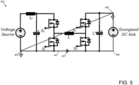
- Figure 5 illustrates an example converter 500 of the type described above in relation to Figure 4 , in which a short circuit fault has occurred that connects the second input terminal 404 and the first output terminal 405. This causes a short circuit current 501 to flow through the common line 407 from the second input terminal 404 to the second output terminal 406.
- Figure 6 illustrates the example converter 500 in which a short circuit fault has occurred that connects the first input terminal 403 to the second output terminal 406. This causes a short circuit current 601 to flow through the common line 407 from the second output terminal 406 to the second input terminal 404.
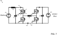
- an inductor Lf is shown representing an inductance of a cable connecting the first input terminal 403 and the first terminal 409 of the first capacitor 408.
- the inductor Lf does not form an essential part of the converter topology.
- Figure 7 illustrates the example converter 500 in which a short circuit fault in the second switch S2 causes current 701 to flow from the battery 401 to the electrical load 402, with a return current 702 flowing back to the battery 401 through the common line 407.
- Figure 8 illustrates the example converter 500 in which a short circuit fault in the fourth switch S4 causes current 801 to flow from the load 402 to the battery 401 when the voltage across the load 402 is higher than the battery voltage, with a return current 802 flowing back to the load 402 through the common line 407.
- the converter 900 illustrated in Figure 9 addresses this problem by including fifth and sixth switches SA1, SA2 in the common line 407.
- the other components of the converter 900 are as described above in relation to Figure 4 .
- the fifth switch SA1 is connected between the second input terminal and the common line 407.
- the sixth switch SA2 is connected between the second output terminal 406 and the common line 407.
- the fifth switch SA1 is connected between the first switch S1 and the second terminal 410 of the first capacitor 408, while the sixth switch SA2 is connected between the third switch S3 and the second terminal 413 of the second capacitor 411.
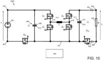
- Figure 10 illustrates an alternative DC-DC converter 1000 similar to the converter 900 of Figure 9 but with the fifth switch SA1 instead connected between the second input terminal 404 and the second terminal 410 of the first capacitor 408 and with the sixth switch SA2 connected between the second output terminal 406 and the second terminal 413 of the second capacitor 411.
- An advantage of this arrangement is that the fifth switch SA1 is not in the boosting current path when the inductor 414 is momentarily connected with the source. The peak current through the fifth switch SA1 will therefore be lower.
- the sixth switch in the position shown in Figure 10 the second capacitor 411 can be isolated from the load 402, which is not possible in the Figure 9 converter.
- the fifth switch SA1 may be in the position shown in Figure 9 while the sixth switch SA2 is in the position shown in Figure 10 and vice versa.
- the fifth and sixth switches SA1, SA2 are strategically placed in the converter topology to provide an additional protection capability.
- the main purpose of the switches SA1, SA2 is to allow the converter to be able to protect against ground fault conditions, as illustrated in Figures 5 and 6 .
- switches SA1 and SA2 may be turned ON.
- the fifth switch SA1 may not be required to be turned ON but doing so will improve the efficiency as current will be shared with the antiparallel diode and MOSFET.
- the sixth switch SA2 does need to be turned ON before starting the converter.
- the fifth and sixth switches SA1, SA2 do not participate in PWM switching operation while the converter is operating but operate only for protection. As the switches SA1, SA2 are in the ON state during converter operation, power losses will be smaller because the diodes and MOSFETs share the current and reduce power losses.
- Addition of the fifth and sixth switches SA1, SA2 also provides for improved fault tolerance in the converter in providing protection in the event of a single switch fault. If, for example, the fourth switch S4 has a short circuit failure (shown in Figure 8 ), operation of the fifth switch SA1 can be used to prevent the battery connecting directly to the DC distribution system. Similarly, if the second switch S2 is short circuit (shown in Figure 7 ), the converter is at similar risk when having a higher battery voltage than the distribution bus where the fourth switch S4 is not able to block the battery current flowing into the DC bus under failure of S2. In such conditions, the sixth switch SA2 can be operated to protect the converter.
- current sensors 901, 902 may be provided on the positive and negative sides of the converter 900, 1000, as shown in Figures 9 and 10 .
- a controller 903 receives current readings from the current sensors 901, 902 and determines if a fault has occurred by detecting a difference between the current readings. If the difference is greater than a predetermined difference threshold, the controller may close all switches, including the fifth and sixth switches SA1, SA2, to protect the converter 900, 1000 from fault currents.
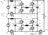
- Figure 11 depicts a two-cell buck boost converter 1100 with integrated protection, which is an extension of the single cell buck boost converter 1000 shown in Figure 10 .
- the converter 1100 comprises first and second converters, each of which are as described above in relation to Figure 10 .
- the reference signs for the various components in the converters are assigned accordingly, i.e. the DC voltage supply 401 1 is connected to the first and second input terminals 403 1 , 404 1 of the first converter 1100 1 and the DC voltage supply 401 2 is connected to the first and second input terminals 403 2 , 404 1 of the second converter 1100 2 .
- the first and second DC voltage supplies 401 1 , 401 2 may be the same supply or may be different supplies.
- the second terminal 406 2 of the second converter 1100 2 is connected to the first terminal 405 1 of the first converter 1100 1 .
- the output voltage supply V 2 across the electrical load 402 is therefore the combined outputs of the first and second converters 1100 1 , 1100 2 .
- the switch SB1 may be omitted. This also provides ground fault capability but may result in a transient current in the event where the energised dc-link positive terminal has a ground fault with the top battery cell negative terminal.
- the presence of a capacitor 411 1 , 411 2 from the centre point 1101 to the positive and negative rails of the converter 1100, corresponding to the first output terminal 405 2 of the second converter 1100 2 and the second output terminal 406 1 of the first converter 1100 1 allows the switch SB1 to be removed without affecting the fault protection capability.
- a controller 903 provides switching signals to each of the switches of the converter 1100 and controls operation of the additional fault switches dependent on current measurements during operation.
Landscapes
- Engineering & Computer Science (AREA)
- Power Engineering (AREA)
- Dc-Dc Converters (AREA)
Applications Claiming Priority (1)
| Application Number | Priority Date | Filing Date | Title |
|---|---|---|---|
| GB202309064 | 2023-06-16 |
Publications (1)
| Publication Number | Publication Date |
|---|---|
| EP4478595A1 true EP4478595A1 (fr) | 2024-12-18 |
Family
ID=91129813
Family Applications (1)
| Application Number | Title | Priority Date | Filing Date |
|---|---|---|---|
| EP24176156.8A Pending EP4478595A1 (fr) | 2023-06-16 | 2024-05-16 | Protection contre les défauts de convertisseur |
Country Status (2)
| Country | Link |
|---|---|
| US (1) | US20240421701A1 (fr) |
| EP (1) | EP4478595A1 (fr) |
Citations (2)
| Publication number | Priority date | Publication date | Assignee | Title |
|---|---|---|---|---|
| WO2021070506A1 (fr) * | 2019-10-10 | 2021-04-15 | 株式会社オートネットワーク技術研究所 | Convertisseur cc/cc |
| US11605951B2 (en) * | 2019-03-29 | 2023-03-14 | Huawei Digital Power Technologies Co., Ltd. | Photovoltaic converter string, control method, and system |
Family Cites Families (2)
| Publication number | Priority date | Publication date | Assignee | Title |
|---|---|---|---|---|
| CN104718681B (zh) * | 2012-10-10 | 2018-06-19 | 住友建机株式会社 | 挖土机及挖土机的控制方法 |
| FR3131812B1 (fr) * | 2022-01-07 | 2023-12-22 | Safran Helicopter Engines | Convertisseur dc/dc pour un reseau electrique propulsif d’aeronef |
-
2024
- 2024-05-16 EP EP24176156.8A patent/EP4478595A1/fr active Pending
- 2024-05-29 US US18/677,149 patent/US20240421701A1/en active Pending
Patent Citations (2)
| Publication number | Priority date | Publication date | Assignee | Title |
|---|---|---|---|---|
| US11605951B2 (en) * | 2019-03-29 | 2023-03-14 | Huawei Digital Power Technologies Co., Ltd. | Photovoltaic converter string, control method, and system |
| WO2021070506A1 (fr) * | 2019-10-10 | 2021-04-15 | 株式会社オートネットワーク技術研究所 | Convertisseur cc/cc |
Non-Patent Citations (2)
| Title |
|---|
| CORTI MATTEO ET AL: "DC Networks Including Multiport DC/DC Converters: Fault Analysis", IEEE TRANSACTIONS ON INDUSTRY APPLICATIONS, IEEE SERVICE CENTER, PISCATAWAY, NJ, US, vol. 52, no. 5, 1 September 2016 (2016-09-01), pages 3655 - 3662, XP011623133, ISSN: 0093-9994, [retrieved on 20160916], DOI: 10.1109/TIA.2016.2572045 * |
| HALSTED CLINT ET AL: "A Novel Transformerless Common-Ground AC/DC Switching Converter with Integral Fault Protection utilizing Active Isolation Techniques", 2021 IEEE ENERGY CONVERSION CONGRESS AND EXPOSITION (ECCE), IEEE, 10 October 2021 (2021-10-10), pages 2231 - 2238, XP034020183, DOI: 10.1109/ECCE47101.2021.9595037 * |
Also Published As
| Publication number | Publication date |
|---|---|
| US20240421701A1 (en) | 2024-12-19 |
Similar Documents
| Publication | Publication Date | Title |
|---|---|---|
| US10826415B2 (en) | Operation of a hybrid electric aircraft propulsion system | |
| US12418170B2 (en) | Electrical power system converter control | |
| US12416244B2 (en) | Aircraft power and propulsion systems comprising permanent magnet electrical machines | |
| US20230373319A1 (en) | Power electronics converter | |
| US11233470B2 (en) | Synchronization of generator and electric motor in a hybrid electric aircraft propulsion system | |
| EP4170893A1 (fr) | Commande de convertisseur de système d'alimentation électrique | |
| US11873109B2 (en) | Electrical power system | |
| EP4478595A1 (fr) | Protection contre les défauts de convertisseur | |
| EP4475424A1 (fr) | Convertisseur électronique de puissance | |
| US12352212B2 (en) | Electrically starting a gas turbine engine | |
| US12562639B2 (en) | Power electronics converter thermal management | |
| US20260039110A1 (en) | Electrical power system and method of control | |
| EP4539288A1 (fr) | Système électrique | |
| US20250293588A1 (en) | Power electronics converter | |
| US12597867B2 (en) | Electrical power system converter control | |
| US12431748B2 (en) | Aircraft power and propulsion systems comprising permanent magnet electrical machines | |
| CA3051334A1 (fr) | Synchronisation du generateur et du moteur electrique d`un systeme de propulsion d`aeronef hybride electrique | |
| US20250293627A1 (en) | Hybrid electric aircraft propulsion system and method | |
| GB2640242A (en) | Power electronics converter |
Legal Events
| Date | Code | Title | Description |
|---|---|---|---|
| PUAI | Public reference made under article 153(3) epc to a published international application that has entered the european phase |
Free format text: ORIGINAL CODE: 0009012 |
|
| STAA | Information on the status of an ep patent application or granted ep patent |
Free format text: STATUS: THE APPLICATION HAS BEEN PUBLISHED |
|
| AK | Designated contracting states |
Kind code of ref document: A1 Designated state(s): AL AT BE BG CH CY CZ DE DK EE ES FI FR GB GR HR HU IE IS IT LI LT LU LV MC ME MK MT NL NO PL PT RO RS SE SI SK SM TR |
|
| STAA | Information on the status of an ep patent application or granted ep patent |
Free format text: STATUS: REQUEST FOR EXAMINATION WAS MADE |
|
| 17P | Request for examination filed |
Effective date: 20250616 |