EP4478802A1 - Procédés et dispositifs de communication par rétrodiffusion - Google Patents
Procédés et dispositifs de communication par rétrodiffusion Download PDFInfo
- Publication number
- EP4478802A1 EP4478802A1 EP22925407.3A EP22925407A EP4478802A1 EP 4478802 A1 EP4478802 A1 EP 4478802A1 EP 22925407 A EP22925407 A EP 22925407A EP 4478802 A1 EP4478802 A1 EP 4478802A1
- Authority
- EP
- European Patent Office
- Prior art keywords
- back scattering
- communication device
- time domain
- communication
- occasion
- Prior art date
- Legal status (The legal status is an assumption and is not a legal conclusion. Google has not performed a legal analysis and makes no representation as to the accuracy of the status listed.)
- Pending
Links
Images



Classifications
-
- H—ELECTRICITY
- H04—ELECTRIC COMMUNICATION TECHNIQUE
- H04B—TRANSMISSION
- H04B7/00—Radio transmission systems, i.e. using radiation field
- H04B7/22—Scatter propagation systems, e.g. ionospheric, tropospheric or meteor scatter
-
- H—ELECTRICITY
- H04—ELECTRIC COMMUNICATION TECHNIQUE
- H04W—WIRELESS COMMUNICATION NETWORKS
- H04W72/00—Local resource management
- H04W72/04—Wireless resource allocation
- H04W72/044—Wireless resource allocation based on the type of the allocated resource
- H04W72/0446—Resources in time domain, e.g. slots or frames
-
- H—ELECTRICITY
- H04—ELECTRIC COMMUNICATION TECHNIQUE
- H04W—WIRELESS COMMUNICATION NETWORKS
- H04W72/00—Local resource management
-
- H—ELECTRICITY
- H02—GENERATION; CONVERSION OR DISTRIBUTION OF ELECTRIC POWER
- H02J—ELECTRIC POWER NETWORKS; CIRCUIT ARRANGEMENTS OR SYSTEMS FOR SUPPLYING OR DISTRIBUTING ELECTRIC POWER; SYSTEMS FOR STORING ELECTRIC ENERGY
- H02J50/00—Circuit arrangements or systems for wireless supply or distribution of electric power
- H02J50/001—Energy harvesting or scavenging
-
- H—ELECTRICITY
- H02—GENERATION; CONVERSION OR DISTRIBUTION OF ELECTRIC POWER
- H02J—ELECTRIC POWER NETWORKS; CIRCUIT ARRANGEMENTS OR SYSTEMS FOR SUPPLYING OR DISTRIBUTING ELECTRIC POWER; SYSTEMS FOR STORING ELECTRIC ENERGY
- H02J50/00—Circuit arrangements or systems for wireless supply or distribution of electric power
- H02J50/20—Circuit arrangements or systems for wireless supply or distribution of electric power using microwaves or radio frequency waves
Definitions
- Embodiments of the present application relate to the field of communication, and in particular, to a method and a device of back scattering communication.
- a zero-power consumption terminal may drive itself to work only after harvesting a radio wave to obtain energy.
- a large number of zero-power consumption terminals need to be accessed, and how to avoid a conflict between different zero-power consumption terminals during back scattering communication is a problem that needs to be solved urgently.
- Back scattering signals are transmitted between different communication devices in a time-division manner, which enables to avoid a conflict between different communication devices during the back scattering communication.
- a method of back scattering communication includes:
- a method of back scattering communication includes:
- a communication device for performing the method in the above first aspect.
- the communication device includes functional modules for performing the method in the above first aspect.
- a communication device for performing the method in the above second aspect.
- the communication device includes functional modules for performing the method in the above second aspect.
- a communication device including a processor and a memory; the memory is configured to store a computer program, and the processor is configured to invoke and execute the computer program stored in the memory, to cause the communication device to perform the method in the above first aspect.
- a communication device including a processor and a memory; the memory is configured to store a computer program, and the processor is configured to invoke and execute the computer program stored in the memory, to cause the communication device to perform the method in the above second aspect.
- an apparatus for implementing the method of any one of the above first aspect to the above second aspect.
- the apparatus includes: a processor, configured to invoke and execute a computer program from a memory, to cause a device equipped with the apparatus to perform the method of any one of the above first aspect to the above second aspect.
- a computer readable storage medium for storing a computer program, and the computer program causes a computer to perform the method of any one of the above first aspect to the above second aspect.
- a computer program product including a computer program instruction, and the computer program instruction causes a computer to perform the method of any one of the above first aspect to the above second aspect.
- a computer program when being executed on a computer, causes the computer to perform the method of any one of the above first aspect to the second aspect.
- the first communication device may determine the time domain resource information for the back scattering communication according to the identification information of the first communication device, or the first communication device may determine the time domain resource information for the back scattering communication based on the identification information of the first communication device and the identification information of the serving cell, so that the first communication device may have its own time domain resource for the back scattering communication, and back scattering signals are transmitted between different communication devices in a time-division manner, which enables to avoid a conflict between different communication devices during the back scattering communication.
- GSM Global System of Mobile communication
- CDMA Code Division Multiple Access
- WCDMA Wideband Code Division Multiple Access
- GPRS General Packet Radio Service
- LTE Long Term Evolution
- LTE-A Advanced long term evolution
- NR New Radio
- NTN Non-Terrestrial communication Network
- UMTS Universal Mobile Telecommunication System
- WLAN Wireless Local Area Network
- IoT internet of things
- WiFi Wireless Fidelity
- 5G fifth-generation communication
- the mobile communication system will not only support the traditional communication, but also support, for example, Device to Device (D2D) communication, Machine to Machine (M2M) communication, Machine Type Communication (MTC), Vehicle to Vehicle (V2V) communication, or Vehicle to everything (V2X) communication, etc., and the embodiments of the present application may also be applied to these communication systems.
- D2D Device to Device
- M2M Machine to Machine
- MTC Machine Type Communication
- V2V Vehicle to Vehicle
- V2X Vehicle to everything
- the communication system in the embodiments of the present application may be applied to a carrier aggregation (CA) scenario, may also be applied to a dual connectivity (DC) scenario, and may also be applied to a standalone (SA) network deployment scenario, or applied to non-standalone (NSA) network deployment scenario.
- CA carrier aggregation
- DC dual connectivity
- SA standalone
- NSA non-standalone
- the communication system in the embodiments of the present application may be applied to an unlicensed spectrum, where the unlicensed spectrum may also be considered as a shared spectrum; or the communication system in the embodiments of the present application may also be applied to a licensed spectrum, where the licensed spectrum may also be considered as an unshared spectrum.
- the communication system in the embodiments of the present application may be applied to an FR1 frequency band (corresponding to a frequency band range of 410 MHz to 7.125 GHz), or may also be applied to an FR2 frequency band (corresponding to a frequency band range of 24.25 GHz to 52.6 GHz), or may also be applied to a new frequency band, such as a high frequency band corresponding to a frequency band range of 52.6 GHz to 71 GHz or corresponding to a frequency band range of 71 GHz to 114.25 GHz.
- the embodiments of the present application describe various embodiments in conjunction with a network device and a terminal device, where the terminal device may also be referred to as a user equipment (UE), an access terminal, a user unit, a user station, a mobile station, a mobile platform, a remote station, a remote terminal, a mobile device, a user terminal, a terminal, a wireless communication device, a user agent or a user apparatus, etc.
- UE user equipment
- the terminal device may be a station (STATION, STA) in the WLAN, may be a cellular phone, a cordless phone, a Session Initiation Protocol (SIP) phone, a Wireless Local Loop (WLL) station, or a personal digital assistant (PDA) device, a handheld device with a wireless communication function, a computing device or other processing devices connected to a wireless modem, a vehicle-mounted device, a wearable device, a terminal device in a next generation communication system such as in an NR network, or a terminal device in a Public Land Mobile Network (PLMN) network evolved in the future, etc.
- STATION station
- STA Session Initiation Protocol
- WLL Wireless Local Loop
- PDA personal digital assistant
- the terminal device may be deployed on land, which includes indoor or outdoor, in handheld, worn or vehicle-mounted; may also be deployed on water (e.g., on a ship, etc.); may also be deployed in the air (e.g., on an airplane, a balloon, a satellite, etc.).
- the terminal device may be a mobile phone, a pad, a computer with a wireless transceiving function, a Virtual Reality (VR) terminal device, an Augmented Reality (AR) terminal device, a wireless terminal device in industrial control, a wireless terminal device in self-driving, a wireless terminal device in remote medical, a wireless terminal device in smart grid, a wireless terminal device in transportation safety, a wireless terminal device in smart city, a wireless terminal device in smart home, a vehicle-mounted communication device, a wireless communication chip/application specific integrated circuit (ASIC)/system on chip (SoC), etc.
- VR Virtual Reality
- AR Augmented Reality
- wireless terminal device in industrial control a wireless terminal device in self-driving
- a wireless terminal device in remote medical a wireless terminal device in smart grid, a wireless terminal device in transportation safety, a wireless terminal device in smart city, a wireless terminal device in smart home, a vehicle-mounted communication device, a wireless communication chip/application specific integrated circuit (ASIC)/system on chip (SoC), etc.
- the terminal device may also be a wearable device.
- the wearable device which is also referred to as a wearable smart device, is a generic term for a device that can be worn, into which the daily wear is intelligently designed and developed by applying wearable technologies, such as glasses, gloves, watches, clothing, and shoes, etc.
- the wearable device is a portable device that is worn directly on the body, or integrated into the user's clothing or accessories.
- the wearable device is not just a hardware device, but also achieves powerful functions through software supporting, data interaction, and cloud interaction.
- a generalized wearable smart device includes for example, a smartwatch or smart glasses, etc., with full functions, large size, and entire or partial functions without relying on a smartphone, as well as, for example, a smart bracelet and smart jewelry for physical sign monitoring, which only focuses on a certain type of application function and needs to be used in conjunction with other devices such as a smartphone.
- the network device may be a device used for communicating with a mobile device.
- the network device may be an Access Point (AP) in the WLAN, a base station (Base Transceiver Station, BTS) in the GSM or CDMA, may also be a base station (NodeB, NB) in the WCDMA, or may also be an evolutionary base station (Evolutionary Node B, eNB or eNodeB) in the LTE, or a relay station or an access point, or a vehicle-mounted device, a wearable device, and a network device or a base station (gNB) in an NR network, or a network device in the PLMN network evolved in the future or a network device in the NTN network, etc.
- AP Access Point
- BTS Base Transceiver Station
- NodeB NodeB
- NB evolved base station
- gNB network device or a base station
- the network device may have a mobile characteristic, for example, the network device may be a mobile device.
- the network device may be a satellite or a balloon station.
- the satellite may be a low earth orbit (LEO) satellite, a medium earth orbit (MEO) satellite, a geostationary earth orbit (GEO) satellite, a high elliptical orbit (HEO) satellite, etc.
- the network device may also be a base station provided on land, water, and other places.
- the network device may provide a service for a cell, and the terminal device communicates with the network device through a transmission resource (such as a frequency domain resource, or a frequency spectrum resource) used by the cell.
- the cell may be a cell corresponding to the network device (such as the base station), the cell may belong to a macro base station or may also belong to a base station corresponding to a small cell, and the small cell here may include: a metro cell, a micro cell, a pico cell, a femto cell, etc., these small cells have characteristics of small coverage range and low transmission power, which are applicable for providing a data transmission service with high speed.
- the communication system 100 may include a network device 110, and the network device 110 may be a device that communicates with a terminal device 120 (also referred to as a communication terminal or a terminal).
- the network device 110 may provide communication coverage for a specific geographical area and may communicate with a terminal device located within the coverage area.
- FIG. 1 exemplarily shows one network device and two terminal devices, and in some embodiments, the communication system 100 may include a plurality of network devices and may include another number of terminal devices within a coverage range of each network device, the embodiments of the present application are not limited thereto.
- the communication system 100 may also include other network entities such as a network controller and a mobility management entity, etc., which are not limited to the embodiments of the present application.
- a device with a communication function in the network/system may be referred to as a communication device.
- the communication device may include the network device 110 and the terminal device 120 with the communication function, and the network device 110 and the terminal device 120 may be the specific devices described above, which will not be repeated herein; the communication device may also include other devices in the communication system 100, such as a network controller, a mobility management entity, and other network entities, which are not limited in the embodiments of the present application.
- the present document relates to a first communication device and a second communication device
- the first communication device may be a terminal device, such as a mobile phone, a machine facility, a customer premise equipment (CPE), an industrial device, a vehicle, etc.
- the second communication device may be a counterpart communication device of the first communication device, such as a network device, a mobile phone, an industrial device, a vehicle, an RFID tag, a zero-power consumption tag, etc.
- the first communication device as a terminal device and the second communication device as a network device are taken as a specific instance herein.
- the "indication" mentioned in the embodiments of the present application may be a direct indication, may also be an indirect indication, or may also represent having an association relationship.
- a indicates B which may mean that A directly indicates B, for example, B may be acquired by A; may also mean that A indirectly indicates B, for example, A indicates C, and B may be acquired by C; or may also mean that there is an association relationship between A and B.
- the term "correspondence” may mean that there is a direct correspondence or indirect correspondence between the two, it may also mean that there is an associated relationship between the two, or it may also mean a relationship of indicating and being indicated or a relationship of configuring and being configured, etc.
- predefined or “preconfigured” may be implemented by pre-saving corresponding codes, tables or other manners that may be used for indicating related information, in the device (for example, including the terminal device and the network device), and the present application does not limit its specific implementation.
- the predefined may refer to what is defined in a protocol.
- the "protocol” may refer to a standard protocol in the field of communication, which may include, for example, an LTE protocol, an NR protocol, and related protocols applied in the future communication system, and the present application is not limited thereto.
- a typical zero-power consumption device is a radio frequency identification (Radio Frequency identification, RFID), which is a technology for implementing an automatic transmission and identification of contactless tag information by means of spatial coupling of wireless radio frequency signals.
- RFID tag is also referred to as a "radio frequency tag” or "electronic tag”.
- Types of electronic tags which are divided according to different power supply methods, may be divided into an active electronic tag, a passive electronic tag and a semi-passive electronic tag.
- the active electronic tag also referred to as an active-type electronic tag, refers to energy for operations of the electronic label is provided by a battery, and the active electronic tag is formed by the battery, a memory and an antenna together, which is different from a activating method of passive radio frequency, it transmits information over a set frequency band until the battery is replaced.
- the passive electronic tag referred to as a passive-type electronic tag, does not support an internal battery, and when the passive electronic tag is close to a reader/writer, the tag is within a near field range formed by antenna radiation of the reader/writer, and the electronic tag antenna generates an induced current by electromagnetic induction, and the induced current drives a chip circuit of the electronic tag.
- the chip circuit transmits identification information stored in the tag to the reader/writer by the electronic tag antenna.
- the semi-active electronic tag inherits advantages of the passive electronic tag with a small size, light weight, cheap price and long service life, and the internal battery supplies power only for very few circuits within the chip when not accessed by the reader/writer, and only when accessed by the reader/writer, the internal battery supplies power to the RFID chip, to increase the reading and writing distance of the tag to be farther, and improve the reliability of communication.
- the RFID is a wireless communication technology.
- the most basic RFID system is formed by two parts: an electronic tag (TAG) and a reader/writer (Reader/Writer).
- the electronic tag is formed by a coupling component and a chip.
- Each electronic tag possesses a unique electronic code and is placed on a measured target to achieve a purpose of marking a target object.
- the reader/writer it can not only read information on the electronic tag, but also write the information on the electronic tag, and at the same time, provide the electronic tag with energy required for communication.
- the electronic tag after entering an electromagnetic field, receives a radio frequency signal transmitted by the reader/writer.
- the passive electronic tag or the passive-type electronic tag obtains energy by using the electromagnetic field generated in space, and transmits the information stored in the electronic tag, and then the reader/writer reads and decodes the information, thereby identifying the electronic tag.
- a typical zero-power consumption communication system includes a reader/writer and a zero-power consumption terminal.
- the reader/writer transmits radio waves to provide energy to the zero-power consumption terminal.
- An energy harvesting module installed in the zero-power consumption terminal may harvest energy carried by radio waves in space (radio waves transmitted by the reader/writer shown in FIG. 2 ), to drive a low-power consumption computing module of the zero-power consumption terminal and implement the back scattering communication.
- the zero-power consumption terminal after obtaining energy, may receive a control command from the reader/writer and transmit data to the reader/writer based on the back scattering method, based on the control signaling.
- the transmitted data may come from data stored in the zero-power consumption terminal itself (for example, an identity or pre-written information, such as a production date, a brand, a manufacturer of the product, etc.).
- the zero-power consumption terminal may also be loaded with various sensors, so as to report data collected by the various sensors based on a zero-power consumption mechanism.
- a zero-power consumption device receives a carrier signal transmitted by a back scattering reader/writer and harvests energy by a wireless radio frequency (RF) energy harvesting module. Then, it functions on a low-power consumption processing module (a logic processing module in FIG. 3 ), to modulate an incoming wave signal and perform back scattering.
- RF radio frequency
- harvesting of electromagnetic wave energy in space is implemented by electromagnetic induction by using an RF module, and then driving of a load circuit (the low-power consumption computing, the sensor, etc.) is implemented, which enables battery-free.
- a load circuit the low-power consumption computing, the sensor, etc.
- the load modulation is a method often used by the electronic tag to transmit data to the reader/writer.
- the load modulation changes the magnitude and phase of the impedance of the electronic tag, by adjusting an electrical parameter of an oscillation circuit of the electronic tag according to a rhythm of a data stream, thereby completing the modulation procedure.
- the load modulation technology mainly has two methods: resistive load modulation and capacitive load modulation.
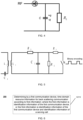
- the resistive load modulation the load is connected in parallel with a resistor, referred to as a load modulation resistor, the resistor is turned on and off according to a clock of the data stream, and the on and off of a switch S are controlled by binary data encoding.
- a circuit schematic diagram of the resistive load modulation is shown in FIG. 5 .
- the load is connected in parallel with a capacitor, replacing the load modulation resistor controlled by the binary data encoding in FIG. 5 .
- the data transmitted by the electronic tag may be represented as binary "1" and "0” by using different forms of codes.
- the wireless radio frequency identification system usually uses one of the following encoding methods: Non Return Zero (NRZ) encoding, Manchester encoding, Unipolar RZ encoding, Differential Bi-Phase (DBP) encoding, Miller encoding and differential encoding. In general terms, 0 and 1 are represented by using different pulse signals.
- energy supply signal carriers it may be a base station, a smart phone, a smart gateway, a charging station, a micro base station, etc.
- a radio wave used for energy supply may be in a low frequency, an intermediate frequency, or a high frequency, etc.
- a radio wave used for energy supply may be a sine wave, a square wave, a triangle wave, a pulse, a rectangular wave, etc.
- the radio wave used for energy supply may be a continuous wave, or a non-continuous wave (i.e., a certain time interruption is allowed).
- the energy supply signal may be a certain signal specified in the 3rd Generation Partnership Project (3GPP) standard, for example, a sounding reference signal (SRS), a physical uplink shared channel (PUSCH), a physical random access channel (PRACH), a physical uplink control channel (PUCCH), a physical downlink control channel (PDCCH), a physical downlink shared channel (PDSCH), a physical broadcast channel (PBCH), etc.
- 3GPP 3rd Generation Partnership Project
- trigger signal carriers it may be a base station, a smart phone, a smart gateway, etc.
- a radio wave used for triggering may be in a low frequency, an intermediate frequency, or a high frequency, etc.
- a radio wave used for triggering may be a sine wave, a square wave, a triangle wave, a pulse, a rectangular wave, etc.
- the radio wave used for triggering may be a continuous wave, or a non-continuous wave (i.e., a certain time interruption is allowed).
- the trigger signal may be a certain signal specified in the 3GPP standard, for example, an SRS, a PUSCH, a PRACH, a PUCCH, a PDCCH, a PDSCH, a PBCH, etc.; or it may also be a new signal.
- the application of battery-free, low-cost passive Internet of Things devices becomes a key technology of the cellular loT, which enriches the types and number of 5G network-linked terminals, and truly implements the Internet of Everything.
- the passive Internet of Things device may be based on the existing zero-power consumption device, such as RFID technology, and extended on this basis, to be applicable for the cellular loT.
- the zero-power consumption terminals may be divided into the following types.
- the zero-power consumption terminal does not need an internal battery, and when the zero-power consumption terminal is close to a network device (such as a reader/writer of the RFID system), the zero-power consumption terminal is within a near field range formed by antenna radiation of the network device. Therefore, an antenna of the zero-power consumption terminal generates an induced current by electromagnetic induction, and the induced current drives the low-power consumption chip circuit of the zero-power consumption terminal. Tasks such as demodulation of a forward link signal and modulation of a backward link signal, etc., are implemented. For the back scattering link, the zero-power consumption terminal uses the back scattering implementation to transmit a signal.
- the passive zero-power consumption terminal does not need an internal battery to drive either the forward link or the backward link, and is a truly zero-power consumption terminal.
- the passive zero-power consumption terminal does not need a battery, and a radio frequency circuit and a baseband circuit of the passive zero-power consumption terminal both are very simple, for example, do not need a low-noise amplifier (LNA), a power amplifier(PA), a crystal oscillator, an analog-to-digital converter (ADC) and other devices, therefore, the passive zero-power consumption terminal has many advantages, such as small size, light weight, very cheap price, and long service life, etc.
- LNA low-noise amplifier
- PA power amplifier
- ADC analog-to-digital converter
- the semi-passive zero-power consumption terminal is not equipped with a conventional battery itself, but may use an RF energy harvesting module to harvest radio wave energy, and at the same time, store the harvested energy in an energy storage unit (such as a capacitor).
- the energy storage unit after obtaining the energy, may drive the low-power consumption chip circuit of the zero-power consumption terminal. Tasks such as demodulation of a forward link signal and modulation of a backward link signal, etc., are implemented.
- the zero-power consumption terminal uses the back scattering implementation to transmit a signal.
- the semi-passive zero-power consumption terminal does not need an internal battery to drive either the forward link or the backward link. Although the energy stored in the capacitor is used in the operation, the energy comes from the radio energy harvested by the energy harvesting module, therefore, the semi-passive zero-power consumption terminal is also a truly zero-power consumption terminal.
- the semi-passive zero-power consumption terminal inherits many of advantages of the passive zero-power consumption terminal, so they have many advantages, such as small size, light weight, very cheap price, and long service life, etc.
- the zero-power consumption terminal used in some scenarios may also be an active zero-power consumption terminal, this type of terminal may have an internal battery.
- the battery is used to drive a low-power consumption chip circuit of the zero-power consumption terminal.
- Tasks such as demodulation of a forward link signal and modulation of a backward link signal, etc., are implemented.
- the zero-power consumption terminal uses the back scattering implementation to transmit a signal. Therefore, the zero-power consumption of this type of terminal is mainly reflected in the fact that the signal transmission of the backward link does not need the terminal's own power, but uses the method of back scattering.
- the internal battery of the active zero-power consumption terminal supplies power to the RFID chip, to increase the reading and writing distance of the tag and improve the reliability of communication. Therefore, it is applied in some scenarios with relatively high requirements on the communication distance, the reading latency, etc.
- the plurality of electronic tags may be a plurality of electronic tags simultaneously within a working range of a reader/writer.
- the plurality of electronic tags transmit data to the reader/writer simultaneously, which will cause a collision of the data of the electronic tags and make the reader/writer unable to read relevant data of each electronic tag normally.
- there are four anti-collision solutions for the data collision which are a space division multiplexing method, a frequency division multiplexing method, a time division multiplexing method and a code division multiplexing method, respectively.
- the RFID anti-collision algorithm is mainly based on a Tridiagonal Matrices (TDMA) algorithm, which may be divided into an ALOHA anti-collision algorithm and a binary-based search algorithm.
- TDMA Tridiagonal Matrices
- the anti-collision algorithm may enable higher system throughput and channel utilization, fewer slots required, and higher data accuracy.
- the polling algorithm and binary search algorithm are both the anti-collision algorithm of the RFID based on TDMA.
- the polling algorithm is to continuously transmit inquiry commands to the tag, and the command contains a serial number.
- the tag checks whether the serial number in the command is the same as its own serial number, and if they are different, the tag will not reply. If the reader/writer does not receive a reply within a specified period of time, it will again transmit an inquiry command containing another serial number, until there is a serial number of a tag meeting the requirement, and then the data communication with the reader/writer is completed. It can be seen that the efficiency of this algorithm is very low.
- the binary search algorithm is that after receiving a reply from the tag, the reader/writer detects a bit that causes the collision, and transmits an inquiry command that can group the tag, according to a detected situation. After receiving the command, a tag checks whether it is in a group that allows communication, and If so, it continues to reply, until there is only one tag, and then the data exchange with the reader/writer is completed. And so on, until data exchanges between all tags and the reader/writer are completed.
- a pure ALOHA algorithm is a process of random access or contention transmission.
- a sender may perform conflict detection in a data transmission procedure and compare the received data with data in a buffer to know whether a data frame is corrupted. If the sender knows that the data frame is corrupted (i.e., the collision is detected), it may retransmit the frame after waiting for a random period of time.
- a frame slot ALOHA algorithm is that the electronic tag randomly selects a slot in each frame to transmit data. All electronic tags must reply synchronously, that is, all electronic tags can only transmit information to the reader/writer at a beginning point of the slot, and the slot for the transmission by each electronic tag is randomly selected.
- BS Binary Search
- tags in the collision are divided into two subsets 0 and 1, query the subsets, and if there is no collision, tags are identified correctly; if there is a collision, the tags are split (for example, the subset 1 is split into two subsets 00 and 01), until all tags in the subsets are identified.
- the zero-power consumption terminal needs to harvest the radio wave transmitted by a network node to obtain energy before it can drive itself to work.
- the number of devices accessed to the network is increased dramatically, and the number of zero-power consumption devices applied in the cellular system will also be very huge.
- a large number of tags need to be accessed, and at the same time, all tags are further required to be identified.
- the traditional conflict solution mechanisms described above, although being able to do so without missing tags, usually have a large latency. Therefore, it is necessary to introduce a new anti-collision solution mechanism in the zero-power consumption communication of the cellular network.
- a solution of back scattering communication is provided by the present application, that different communication devices transmit back scattering signals in a time-division manner, which can avoid the conflict between different communication devices during the back scattering communication.
- FIG. 6 is a schematic flow chart of a method 200 of back scattering communication, according to the embodiments of the present application, and as shown in FIG. 6 , the method 200 of back scattering communication may include at least some of the following contents: S210, determining by a first communication device, time domain resource information for the back scattering communication according to first information; where the first information is identification information of the first communication device, or the first information is identification information of the first communication device and identification information of a serving cell.
- the back scattering communication may be communication between the first communication device and a second communication device.
- the first communication device is a terminal device
- the second communication device is a network device, that is, the communication between the first communication device and the second communication device may be uplink and downlink communication.
- the first communication device is a terminal device
- the second communication device is another terminal device, that is, the communication between the first communication device and the second communication device may be sidelink communication.
- the first communication device is taken as a terminal device and the second communication device is taken as a network device as an example to explain.
- the identification information of the terminal device may be a terminal identification (UE ID), or other information used to identify the terminal device, such as a terminal index, etc., which is not limited by the present application.
- UE ID terminal identification
- the terminal index such as a terminal index, etc.
- the identification information of the serving cell may be a cell identification (Identity, ID), or other information used to identify the serving cell, such as a cell index, etc., which is not limited by the present application.
- the embodiments of the present application may be applied to a cellular Internet of Things system, such as a cellular passive Internet of Things system, or may also be applied to other scenarios in which the terminal device transmits information to the network device in a zero-power consumption communication manner or a battery-free communication manner, but the present application is not limited thereto.
- the embodiments of the present application may be applicable to one-to-many communication modes such as broadcast, multicast, and packet paging, etc.
- one-to-many communication modes such as broadcast, multicast, and packet paging, etc.
- the network device transmits a broadcast message, a multicast message, a packet paging message, etc.
- back scattering signals are transmitted by different terminals in a time-division manner, which can avoid the conflict between different terminals during the back scattering communication.
- the embodiments of the present application are also applicable to one-to-one communication modes, which is not limited by the present application.
- the terminal device may be a zero-power consumption terminal; specifically, the terminal device obtains energy by energy harvesting, to be used for communication, information collecting and processing.
- the terminal device may also be other terminals, such as a terminal that may achieve communication, information collecting and processing without the capability harvesting.
- a terminal that may achieve communication, information collecting and processing without the capability harvesting.
- the present application is not limited thereto.
- the zero-power consumption device needs to obtain energy for communication by the energy harvesting, and on the one hand, it may perform the energy harvesting on environmental energy such as thermal energy, light energy, kinetic energy, etc., on the other hand, it may perform the energy harvesting on radio frequency signals, to obtain energy for communication, and then perform a corresponding communication procedure based on the back scattering.
- a signal for the energy harvesting i.e., an energy supply signal
- the network device needs to provide control information to schedule the information transmission, which may be referred to as a scheduling signal/trigger signal.
- the trigger signal and the energy supply signal may be a same signal or two independent signals.
- a carrier capable of carrying the communication is needed, and the carrier may be a signal independent from the energy supply signal and the trigger signal, or may be one signal with the energy supply signal, or one signal with the trigger signal.
- frequency bands of the energy supply signal, the carrier signal, and the trigger signal may be completely different, completely the same, or partially the same.
- the network device continuously or intermittently transmits the energy supply signal in a certain frequency band, the zero-power consumption device harvests energy, and after obtaining the energy, the zero-power consumption device may perform the corresponding communication procedure, such as measuring, receiving a channel/signal, transmitting a channel/signal, etc.
- the terminal device transmits a back scattering signal according to the determined time domain resource for the back scattering communication.
- the back scattering signal is obtained by scrambling the identification information of the terminal device.
- the terminal device obtains the back scattering signal by scrambling a cyclic redundancy check (CRC) based on its UE ID.
- CRC cyclic redundancy check
- the terminal device receives a first scheduling signal for scheduling or triggering the back scattering communication, transmitted by the network device, and after receiving the first scheduling signal, the terminal device determines the time domain resource information for the back scattering communication based on the first information. Further, in response to the first scheduling signal, the terminal device transmits a back scattering signal according to the determined time domain resource for the back scattering communication.
- the terminal device obtains energy by energy harvesting, to be used for communication, information collecting and processing. And in a case where the first scheduling signal is an energy supply signal of the terminal device, the terminal device monitors the first scheduling signal in the energy harvesting procedure. Or, in a case where the energy supply signal of the terminal device does not contain scheduling information, the terminal device monitors the first scheduling signal after the energy harvesting.
- the first scheduling signal may be a broadcast signal or a multicast signal transmitted by the network device to the zero-power consumption terminal within a coverage range, or the first scheduling signal may be a paging signal transmitted by the network device to a certain group of zero-power consumption terminals, or the first scheduling signal may be other control signals transmitted by the network device to a zero-power consumption terminal within a coverage range, etc.
- the time domain resource information for the back scattering communication includes but not limited to at least one of: a starting location of a time domain resource for the back scattering communication, and a back scattering occasion for the back scattering communication.
- the time domain resource for the back scattering communication may be referred to as a back scattering occasion (backscatter occasion, BO).
- back scattering occasion (backscatter occasion, BO).
- the back scattering occasion described herein is the time domain resource for the back scattering communication.
- Example 1 the time domain resource information for the back scattering communication includes a starting location of a time domain resource for the back scattering communication.
- S210 described above may specifically include: determining by the terminal device, a first duration according to the first information; and determining by the terminal device, the starting location of the time domain resource for the back scattering communication according to the first duration and a first time domain location.
- the terminal device may be configured with N durations, and the terminal device may determine the first duration from the N durations based on the first information, where N is a positive integer.
- the terminal device determines the first duration corresponding to the terminal device from the N durations according to a UE ID, or the UE ID and a cell ID.
- the network device may semi-statically configure X durations, where X is a positive integer; and the network device indicates the N durations of the X durations by the first scheduling signal, or the network device indicates the N durations of the X durations by a signal other than the first scheduling signal.
- the network device indicates the N durations by the first scheduling signal, or the network device indicates the N durations by a signal other than the first scheduling signal.
- the terminal device may determine an index of the first duration used by the terminal device from the N durations based on the following formula 1: UE ID mod N + 1 where UE ID denotes an identification of the terminal device, and mod denotes a modulo operation.
- the above formula 1 may also be (UE ID mod N).
- the terminal device may determine an index of the first duration used by the terminal device from the N durations based on the following formula 2 or formula 3: UE ID ⁇ Cell ID mod N + 1 UE ID ⁇ Cell ID mod N + 1 where UE ID denotes an identifier of the terminal device, Cell ID denotes a serving cell identification, V denotes an OR operation, ⁇ denotes an AND operation, and mod denotes a modulo operation.
- the above formula 2 may also be ( UE ID ⁇ Cell ID ) mod N
- the above formula 3 may also be ( UE ID ⁇ Cell ID ) mod N.
- the "OR operation” in the above formula 2 may also be replaced by an “XOR operation” or an “XNOR operation”.
- the "AND operation” in the above formula 3 may also be replaced by the "XOR operation” or the "XNOR operation”.
- a unit of the first duration may be a basic unit for the back scattering communication, such as a symbol, a slot, a subframe, a frame, or other units, etc.
- the terminal device may determine the first duration based on the following formula 4: UE ID ⁇ Cell ID mod T max where UE ID denotes an identification of the terminal device, Cell ID denotes a serving cell identification, V denotes an OR operation, T max denotes a maximum value of the first duration, and mod denotes a modulo operation.
- the "OR operation" in the above formula 4 may also be replaced by an “AND operation” or an "XOR operation” or an “XNOR operation”.
- the terminal device may determine the first duration based on the following formula 5: UE ID mod T max where UE ID denotes an identification of the terminal device, T max denotes a maximum value of the first duration, and mod denotes a modulo operation.
- T max may be pre-configured, or T max may be configured by the network device, or T max may be semi-statically configured, or T max may be configured by the network device by the first scheduling signal, or T max may be configured by the network device by a signal other than the first scheduling signal, or T max may be configured by the network device by other control information (carried by a signal other than the first scheduling signal).
- a unit of T may be an absolute time unit such as microsecond (us), millisecond (ms), or second (s).
- the zero-power consumption device performs the back scattering communication at the moment T 0 +T, based on the moment T 0 at which the first scheduling signal is received.
- a unit of T may be a symbol, a slot, a subframe, a frame, a basic time unit in the zero-power consumption communication, etc.
- the zero-power consumption device performs the back scattering communication after the T-th time unit after a time unit in which the first scheduling signal is received.
- the terminal device performs the back scattering communication after T OFDM symbols after receiving the first scheduling signal; if the unit of T is a slot, the terminal device performs the back scattering communication at a starting location of a T-th slot after a slot in which the first scheduling signal is received.
- OFDM orthogonal frequency-division multiplexing
- the unit of T and T 0 may be an absolute time unit, such as us, ms, or s, etc.
- the zero-power consumption device performs the back scattering communication at the moment T 0 +T based on T 0 indicated by the received first scheduling signal.
- the unit of T and T 0 may be a symbol, a slot, a subframe, a frame, a basic time unit in the zero-power consumption communication, etc.
- the zero-power consumption device performs the back scattering communication after T time units after the time unit T 0 indicated by the received first scheduling signal. For example: if the unit of T and T 0 is an OFDM symbol, the back scattering communication is performed after T OFDM symbols after T 0 indicated by the received first scheduling signal; if the unit of T and T 0 is a time slot, the back scattering communication is performed at a starting location of a T-th time slot after the T 0 slot indicated by the received first scheduling signal.
- the first time domain location is determined based on the first scheduling signal for scheduling or triggering the back scattering communication. Specifically, the first time domain location is a moment at which the terminal device receives the first scheduling signal, or the first time domain location is a starting time domain location when the terminal device receives the first scheduling signal, or the first time domain location is an ending time domain location at which the terminal device receives the first scheduling signal, or the first time domain location is a time unit in which the first scheduling signal is located, or the first time domain location is a time unit in which a starting time domain location of the first scheduling signal is located, or the first time domain location is a time unit in which an ending time domain location of the first scheduling signal is located, or the first time domain location is indicated by the first scheduling signal.
- the moment at which the terminal device receives the first scheduling signal may be expressed by an absolute time unit, such as us, ms, s, etc.
- the starting time domain location at which the terminal device receives the first scheduling signal may be expressed by an absolute time unit, such as us, ms, s, etc., or expressed by a time unit such as a symbol, a slot, a subframe, a frame, etc.
- the ending time domain location at which the terminal device receives the first scheduling signal may be expressed by an absolute time unit, such as us, ms, s, etc., or expressed by a time unit such as a symbol, a slot, a subframe, a frame, etc.
- the time unit associated with the first time domain location may be a time unit, such as a symbol, a slot, a subframe, or a frame, etc.
- the first time domain location is pre-configured, or the first time domain location is agreed by a protocol.
- the first time domain location may also be indicated by the network device by a signal other than the first scheduling signal.
- the network device indicates the first time domain location by control information.
- T 0 is not indicated by the first scheduling signal.
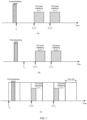
- T 0 is the moment at which a UE1 and a UE2 receive the first scheduling signal, the first duration corresponding to the UE1 is T 1 , and the first duration corresponding to the UE2 is T2, and then, the UE1 transmits a back scattering signal at a moment T 0 +T 1 , and the UE2 transmits a back scattering signal at a moment T 0 +T 2 .
- T 0 is the moment at which a UE1 and a UE2 receive the first scheduling signal, the first duration corresponding to the UE1 is T 1 , and the first duration corresponding to the UE2 is T2, and then, the UE1 transmits a back scattering signal at a moment T 0 +T 1 , and the UE2 transmits a back scattering signal at a moment T 0 +T 2 .
- T 0 is the moment at which a UE1 and a UE2 receive the first scheduling signal
- T 0 is a pre-configured moment or a moment agreed by the protocol
- the UE1 and the UE2 know that T 0 is located at a moment T 0 after the first scheduling signal, the first duration corresponding to the UE1 is T 1 , and the first duration corresponding to the UE2 is T 2 , and then, the UE1 transmits a back scattering signal at a moment T 0 +T 1 , and the UE2 transmits a back scattering signal at a moment T 0 +T 2 .
- T 0 is the starting location of the time unit in which the first scheduling signal is located
- the first duration corresponding to the UE1 is T 1
- the first duration corresponding to the UE2 is T 2
- the UE1 transmits a back scattering signal at a starting location of a time unit in which T 0 +T 1 is located (particularly, the back scattering signal may be transmitted at the start location of the time unit, or the back scattering signal may be transmitted after an offset within the time unit)
- the UE2 transmits a back scattering signal at a starting location of a time unit in which T 0 +T 2 is located (particularly, the back scattering signal may be transmitted at the starting location of the time unit, or the back scattering signal may be transmitted after an offset within the time unit).
- T 0 is indicated by the first scheduling signal.
- the first scheduling signal indicates T 0
- the first duration corresponding to the UE1 is T 1
- the first duration corresponding to the UE2 is T 2
- the UE1 transmits a back scattering signal at a moment T 0 +T 1
- the UE2 transmits a back scattering signal at a moment T 0 +T 2
- the UE1 transmits a back scattering signal at a moment T 0 +T 2
- T 0 +T 2 As shown in (b) of FIG.
- the first scheduling signal indicates a starting location of a time unit in which T 0 is located, the first duration corresponding to the UE1 is T 1 , and the first duration corresponding to the UE2 is T 2 , and then, the UE1 transmits a back scattering signal in a time unit in which T 0 +T 1 is located (particularly, the back scattering signal may be transmitted at a starting location of the time unit, or the back scattering signal may be transmitted after an offset within the time unit), and the UE2 transmits a back scattering signal in a time unit in which T 0 +T 2 is located (particularly, the back scattering signal may be transmitted at a starting location of the time unit, or the back scattering signal may be transmitted after an offset within the time unit).
- Example 2 the time domain resource information for the back scattering communication includes the back scattering occasion for the back scattering communication.
- S210 described above may specifically include: determining by the terminal device, the back scattering occasion for the back scattering communication from at least one available back scattering occasion according to the first information.
- the at least one available back scattering occasion is determined based on a time domain resource structure.
- the at least one available back scattering occasion is a part or all of back scattering occasions in a first time domain resource set.
- the UE1 may determine the BO for the back scattering communication from the first time domain resource set 1 based on one of the above formula 1 to formula 3, and the UE2 may determine the BO for the back scattering communication from the first time domain resource set 1 based on one of the above formula 1 to formula 3.
- the BOs determined by the UE1 and the UE2 for the back scattering communication are different.
- the terminal device determines the first back scattering occasion pattern from the plurality of back scattering occasion patterns according to the following formula: UE ID mod N + 1 , or UE ID ⁇ Cell ID mod N + 1 , or UE ID ⁇ Cell ID mod N + 1 where N is a number of the plurality of back scattering occasion patterns, UE ID denotes an identification of the first communication device, Cell ID denotes a serving cell identification, V denotes an OR operation, ⁇ denotes an AND operation, and mod denotes a modulo operation.
- the terminal device determines the first back scattering occasion pattern from the plurality of back scattering occasion patterns according to the following formula: UE groupID mod N + 1 , or UE groupID ⁇ Cell ID mod N + 1 , or UE groupID ⁇ Cell ID mod N + 1 where N is a number of the plurality of back scattering occasion patterns, UE groupID denotes an identification of the terminal group to which the first communication device belongs, Cell ID denotes a serving cell identification, V denotes an OR operation, ⁇ denotes an AND operation, and mod denotes a modulo operation.
- the terminal device may determine the first back scattering occasion pattern from the plurality of back scattering occasion patterns based on one of the above formula 1 to formula 3.
- UE ID in the above formula 1 to formula 3 may be replaced by UE groupID , thereby determining the first back scattering occasion pattern from the plurality of back scattering occasion patterns.
- the plurality of back scattering occasion patterns are indicated by the network device by the first scheduling signals for scheduling or triggering the back scattering communication, or the plurality of back scattering occasion patterns are indicated by the network device by a signal other than the first scheduling signals, or the plurality of back scattering occasion patterns are pre-configured, or the plurality of back scattering occasion patterns are agreed by a protocol, or the plurality of back scattering occasion patterns are semi-statically configured by the network device.
- the plurality of back scattering occasion patterns do not overlap with each other, or the plurality of back scattering occasion patterns partially overlap with each other.
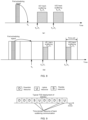
- the UE1 corresponds to a first BO pattern and the UE2 corresponds to a second BO pattern.
- a second time unit, a fourth time unit and a fifth time unit in a first time domain resource set 1 are indicated by the first BO pattern, and locations of time units indicated by the first BO pattern in other first time domain resource sets are consistent with those in the first time domain resource set 1;
- a first time unit and a third time unit in a first time domain resource set 1 are indicated by a second BO pattern, and locations of time units indicated by the second BO pattern in other first time domain resource sets are consistent with those in the first time domain resource set 1.
- the UE1 determines the BO for the back scattering communication from the first BO pattern based on one of the above formula 1 to formula 3, and the UE2 determines the BO for the back scattering communication from the second BO pattern based on one of the above formula 1 to formula 3.
- a BO1 in the first BO pattern occupies a second time unit in the first time domain resource set 1
- a BO2 in the first BO pattern occupies a fourth time unit in the first time domain resource set 1
- a BOk in the first BO pattern occupies a n-th time unit in the first time domain resource set 1
- locations of time units occupied by the first BO pattern in other first time domain resource sets are consistent with those in the first time domain resource set 1
- a BO1 of the second BO pattern occupies a first time unit in the first time domain resource set 1
- a BO2 of the second BO pattern occupies a fourth time unit in the first time domain resource set 1
- a BOk of the second BO pattern occupies a n-th time unit in the first time domain resource set 1
- locations of time units occupied by the second BO pattern in other first time domain resource sets are consistent with those in the first time domain resource set 1.
- the first time domain resource set may be understood as 1 frame
- the first BO pattern may be understood as a frame structure
- the first BO pattern may be regarded as a configuration of a frame structure
- the first time domain resource set 1 denotes frame x
- the first time domain resource set 2 denotes frame x+1
- the same frame structure configuration is used in continuous frames. That is, the first BO pattern is a BO mapping for the first time domain resource set, and specifically, each first time domain resource set uses BOs determined by the first BO pattern in the time domain.
- the network device may determine the identification information of the terminal device according to a time unit of transmitting the first scheduling signal and a time unit of receiving the back scattering signal; and the network device descrambles the back scattering signal according to the identification information of the terminal device.
- the network device Since the back scattering signal is obtained by scrambling the identification information of the terminal device, the network device descrambles the back scattering signal according to the identification information of the terminal device. Specifically, for example, the network device receives the back scattering signal 1, and at this time, the network device descrambles the back scattering signal 1 based on the UE ID of the UE1 and the descrambling is successful; and the network device descrambles the back scattering signal 1 based on the UE ID of the UE2 and the descrambling is unsuccessful, then the network device may judge that the terminal device transmitting the back scattering signal 1 is the UE1.
- the network device may determine the first duration according to a time unit for transmitting the first scheduling signal and a time unit for receiving the back scattering signal, and determine an identification of the terminal device based on the following formula 7 or formula 8.
- Index of the first duration T UE ID mod N + 1 where UE ID denotes the identification of the terminal device, N denotes a number of the first duration configured, and mod denotes a modulo operation.
- Index of the first duration T UE ID ⁇ Cell ID mod T max where UE ID denotes the identification of the terminal device, Cell ID denotes a serving cell identification, V denotes an OR operation, T max denotes a maximum value of the first duration, and mod denotes a modulo operation.
- the "OR operation" in the above formula 8 may also be replaced by an “AND operation” or an "XOR operation” or an "XNOR operation”.
- the network device may check the solving of the back scattering communication based on the plurality of UE IDs. Specifically, for example, the network device receives a back scattering signal 1 and a back scattering signal 2. At this time, the network device descrambles the back scattering signal 1 based on the UE IDs of the UE1 and the UE2 respectively, and the descrambling of the UE ID of the UE1 is successful; the network device descrambles the back scattering signal 2 based on the UE IDs of the UE1 and the UE2 respectively, and the descrambling of the UE ID of the UE2 is successful. Then, the network device may judge that the terminal device transmitting the back scattering signal 1 is the UE1 and the terminal device transmitting the back scattering signal 2 is the UE2.
- the network device determines whether to proceed to the next scheduling according to whether the back scattering signal is correctly solved.
- the first communication device may determine time domain resource information for the back scattering communication according to identification information of the first communication device, or the first communication device may determine the time domain resource information for the back scattering communication according to the identification information of the first communication device and identification information of the serving cell. Therefore, the first communication device may have its own time domain resources for the back scattering communication, and different terminals transmit back scattering signals in the time-division manner, which can avoid the conflict between different terminals during the back scattering communication, and reduce the probability of the collision.
- the second communication device may determine a possible UE ID based on a relationship between the back scattering signal and the first scheduling signal in the time domain, and further perform a reception process of the back scattering signal based on the determined UE ID.
- FIG. 12 is a schematic flow chart of a method 300 of back scattering communication, according to the embodiments of the present application, and as shown in FIG. 12 , the method 300 of back scattering communication may include at least some of the following contents:
- the back scattering communication may be communication between the first communication device and a second communication device.
- the first communication device is a terminal device
- the second communication device is a network device, that is, the communication between the first communication device and the second communication device may be uplink and downlink communication.
- the first communication device is a terminal device
- the second communication device is another terminal device, that is, the communication between the first communication device and the second communication device may be sidelink communication.
- the first communication device is taken as a terminal device and the second communication device is taken as a network device as an example to explain.
- the identification information of the terminal device may be a terminal identification (UE ID), or other information used to identify the terminal device, such as a terminal index, etc., which is not limited by the present application.
- UE ID terminal identification
- the terminal index such as a terminal index, etc.
- the identification information of the serving cell may be a cell identification (identity, ID), or other information used to identify the serving cell, such as a cell index, etc., which is not limited by the present application.
- the embodiments of the present application may be applied to a cellular Internet of Things system, such as a cellular passive Internet of Things system, or may also be applied to other scenarios in which the terminal device transmits information to the network device in a zero-power consumption communication manner or a battery-free communication manner, but the present application is not limited thereto.
- the embodiments of the present application may be applicable to one-to-many communication modes such as broadcast, multicast, and packet paging, etc.
- one-to-many communication modes such as broadcast, multicast, and packet paging, etc.
- the network device transmits a broadcast message, a multicast message, a packet paging message, etc.
- back scattering signals are transmitted by different terminals in a time-division manner, which can avoid the conflict between different terminals during the back scattering communication.
- the embodiments of the present application are also applicable to one-to-one communication modes, which is not limited by the present application.
- the terminal device may be a zero-power consumption terminal; specifically, the terminal device obtains energy by energy harvesting, to be used for communication, information collecting and processing.
- the terminal device may also be other terminals, such as a terminal that may achieve communication, information collecting and processing without the capability harvesting.
- a terminal that may achieve communication, information collecting and processing without the capability harvesting.
- the present application is not limited thereto.
- the zero-power consumption device In the cellular network, due to no battery to supply energy, the zero-power consumption device needs to obtain energy for communication by performing the energy harvesting on radio frequency signals (or other environmental signals), and then perform the corresponding communication procedure based on the back scattering.
- a signal for the energy harvesting i.e., an energy supply signal
- the network device When the communication is performed based on scheduling, the network device needs to provide control information to schedule the information transmission, which may be referred to as a scheduling signal/trigger signal.
- the trigger signal and the energy supply signal may be a same signal or two independent signals.
- a carrier capable of carrying the communication is needed, and the carrier may be a signal independent from the energy supply signal and the trigger signal, or may be one signal with the energy supply signal, or one signal with the trigger signal.
- frequency bands of the energy supply signal, the carrier signal, and the trigger signal may be completely different, completely the same, or partially the same.
- the network device continuously or intermittently transmits the energy supply signal in a certain frequency band, the zero-power consumption device harvests energy, and after obtaining the energy, the zero-power consumption device may perform the corresponding communication procedure, such as measuring, receiving a channel/signal, transmitting a channel/signal, etc.
- the network device Since the back scattering signal is obtained by scrambling the identification information of the terminal device, the network device descrambles the back scattering signal according to the identification information of the terminal device. Specifically, for example, the network device receives the back scattering signal 1, and at this time, the network device descrambles the back scattering signal 1 based on the UE ID of the UE1 and the descrambling is successful; and the network device descrambles the back scattering signal 1 based on the UE ID of the UE2 and the descrambling is unsuccessful, and then, the network device may judge that the terminal device transmitting the back scattering signal 1 is the UE1.
- the network device determines whether to proceed to the next scheduling according to whether the back scattering signal is correctly solved.
- the first duration is determined by the terminal device from the N durations according to the following formula: UE ID mod N + 1 , or UE ID ⁇ Cell ID mod N + 1 , or UE ID ⁇ Cell ID mod N + 1 where UE ID denotes an identifier of the terminal device, Cell ID denotes a serving cell identification, V denotes an OR operation, ⁇ denotes an AND operation, and mod denotes a modulo operation.
- the first duration is determined by the terminal device from the N durations according to the following formula: UE ID ⁇ Cell ID mod T max , or , UE ID mod T max where UE ID denotes an identification of the terminal device, Cell ID denotes a serving cell identification, V denotes an OR operation, T max denotes a maximum value of the first duration, and mod denotes a modulo operation.
- the T max is pre-configured, or the T max is configured by the network device, or the T max is semi-statically configured, or the T max is configured by the network device by the first scheduling signal.
- the N durations are pre-configured, or the N durations are configured by the network device, or the N durations are semi-statically configured, or the N durations are configured by the network device by the first scheduling signal.
- the first time domain location is a moment at which the terminal device receives the first scheduling signal, or the first time domain location is a starting time domain location at which the terminal device receives the first scheduling signal, or the first time domain location is an ending time domain location at which the terminal device receives the first scheduling signal, or the first time domain location is a time unit in which the first scheduling signal is located, or the first time domain location is a time unit in which a starting time domain location of the first scheduling signal is located, or the first time domain location is a time unit in which an ending time domain location of the first scheduling signal is located, or the first time domain location is indicated by the first scheduling signal.
- the time domain resource information for the back scattering communication includes a back scattering occasion for the back scattering communication; where the back scattering occasion for the back scattering communication is determined by the terminal device from at least one available back scattering occasion based on the first information.
- the at least one available back scattering occasion is determined based on a time domain resource structure.
- the at least one available back scattering occasion is a part or all of time units in the time domain resource structure that are available for back scattering.
- the at least one available back scattering occasion is a part or all of back scattering occasions in a first time domain resource set.
- the at least one available back scattering occasion is determined by the terminal device based on a length of the first time domain resource set and a back scattering occasion location in the first time domain resource set.
- the at least one available back scattering occasion is a part or all of back scattering occasions in a first back scattering occasion pattern; where the first back scattering occasion pattern indicates a time domain location of a back scattering occasion that is available for the back scattering communication, in a first time domain resource set.
- the first back scattering occasion pattern is indicated by the network device by the first scheduling signal, or the first back scattering occasion pattern is indicated by the network device by a signal other than the first scheduling signal, or the first back scattering occasion pattern is semi-statically configured by the network device.
- the first back scattering occasion pattern is determined by the terminal device from a plurality of back scattering occasion patterns based on the identification information of the terminal device, or the first back scattering occasion pattern is determined by the terminal device from a plurality of back scattering occasion patterns based on the identification information of the terminal device and the identification information of the serving cell, or the first back scattering occasion pattern is determined by the terminal device from a plurality of back scattering occasion patterns based on identification information of a terminal group to which the terminal device belongs, or the first back scattering occasion pattern is determined by the terminal device from a plurality of back scattering occasion patterns based on identification information of a terminal group to which the terminal device belongs and the identification information of the serving cell.
- the first back scattering occasion pattern is determined by the terminal device from the plurality of back scattering occasion patterns based on the following formula: UE ID mod N + 1 , or UE ID ⁇ Cell ID mod N + 1 , or UE ID ⁇ Cell ID mod N + 1 where N is a number of the plurality of back scattering occasion patterns, UE ID denotes an identification of the terminal device, Cell ID denotes a serving cell identification, V denotes an OR operation, ⁇ denotes an AND operation, and mod denotes a modulo operation.
- the first back scattering occasion pattern is determined by the terminal device from the plurality of back scattering occasion patterns based on the following formula: UE groupID mod N + 1 , or UE groupID ⁇ Cell ID mod N + 1 , or UE groupID ⁇ Cell ID mod N + 1 where N is a number of the plurality of back scattering occasion patterns, UE groupID denotes an identification of the terminal group to which the terminal device belongs, Cell ID denotes a serving cell identification, V denotes an OR operation, ⁇ denotes an AND operation, and mod denotes a modulo operation.
- the plurality of back scattering occasion patterns are indicated by the network device by the first scheduling signal, or the plurality of back scattering occasion patterns are indicated by the network device by a signal other than the first scheduling signal, or the plurality of back scattering occasion patterns are pre-configured, or the plurality of back scattering occasion patterns are agreed by a protocol, or the plurality of back scattering occasion patterns are semi-statically configured by the network device.
- the plurality of back scattering occasion patterns do not overlap with each other, or the plurality of back scattering occasion patterns partially overlap with each other.
- the back scattering signal is obtained by scrambling the identification information of the terminal device.
- the terminal device obtains energy by the energy harvesting, to be used for communication, information collecting and processing.
- the first scheduling signal is an energy supply signal of the terminal device.
- the network device transmits the energy supply signal of the terminal device to the terminal device.
- the network device may check the solving of the back scattering communication based on the plurality of UE IDs.
- the network device determines whether to proceed to the next scheduling based on whether the back scattering signal is correctly solved.
- the first communication device may determine time domain resource information for the back scattering communication according to identification information of the first communication device, or the first communication device may determine the time domain resource information for the back scattering communication according to the identification information of the first communication device and identification information of the serving cell. Therefore, the first communication device may have its own time domain resources for the back scattering communication, and different terminals transmit back scattering signals in the time-division manner, which can avoid the conflict between different terminals during the back scattering communication, and reduce the probability of the collision.
- the second communication device may determine a possible UE ID based on a relationship between the back scattering signal and the first scheduling signal in the time domain, and further perform a reception process of the back scattering signal based on the determined UE ID.
- FIG. 13 shows a schematic block diagram of a communication device 400, according to the embodiments of the present application.
- the communication device 400 is a first communication device, and the communication device 400 includes: a processing unit 410, configured to determine time domain resource information for the back scattering communication according to first information; where the first information is identification information of the first communication device, or the first information is identification information of the first communication device and identification information of a serving cell.
- the time domain resource information for the back scattering communication includes at least one of: a starting location of a time domain resource for the back scattering communication, and a back scattering occasion for the back scattering communication.
- the time domain resource information for the back scattering communication includes a starting location of a time domain resource for the back scattering communication; the processing unit 410 is specifically configured to:
- the first time domain location is determined based on a first scheduling signal for scheduling or triggering the back scattering communication.
- the first time domain location is a moment at which the first communication device receives the first scheduling signal, or the first time domain location is a starting time domain location at which the first communication device receives the first scheduling signal, or the first time domain location is an ending time domain location at which the first communication device receives the first scheduling signal, or the first time domain location is a time unit in which the first scheduling signal is located, or the first time domain location is a time unit in which a starting time domain location of the first scheduling signal is located, or the first time domain location is a time unit in which an ending time domain location of the first scheduling signal is located, or the first time domain location is indicated by the first scheduling signal.
- the first time domain location is pre-configured, or the first time domain location is agreed by a protocol, or the first time domain location is indicated by a second communication device by a signal other than the first scheduling signal.
- the processing unit 410 is specifically configured to:
- the processing unit 410 is specifically configured to:
- the at least one available back scattering occasion is a part or all of back scattering occasions in a first time domain resource set.
- the first communication device 400 further includes: the communication unit 420; in a case where a first scheduling signal for scheduling or triggering the back scattering communication is an energy supply signal of the first communication device, the communication unit 420 is further configured to monitor the first scheduling signal during the energy harvesting.
Landscapes
- Engineering & Computer Science (AREA)
- Computer Networks & Wireless Communication (AREA)
- Signal Processing (AREA)
- Power Engineering (AREA)
- Mobile Radio Communication Systems (AREA)
Applications Claiming Priority (1)
| Application Number | Priority Date | Filing Date | Title |
|---|---|---|---|
| PCT/CN2022/076104 WO2023151045A1 (fr) | 2022-02-11 | 2022-02-11 | Procédés et dispositifs de communication par rétrodiffusion |
Publications (2)
| Publication Number | Publication Date |
|---|---|
| EP4478802A1 true EP4478802A1 (fr) | 2024-12-18 |
| EP4478802A4 EP4478802A4 (fr) | 2025-12-03 |
Family
ID=87563364
Family Applications (1)
| Application Number | Title | Priority Date | Filing Date |
|---|---|---|---|
| EP22925407.3A Pending EP4478802A4 (fr) | 2022-02-11 | 2022-02-11 | Procédés et dispositifs de communication par rétrodiffusion |
Country Status (4)
| Country | Link |
|---|---|
| US (1) | US20240405863A1 (fr) |
| EP (1) | EP4478802A4 (fr) |
| CN (1) | CN118661457A (fr) |
| WO (1) | WO2023151045A1 (fr) |
Cited By (1)
| Publication number | Priority date | Publication date | Assignee | Title |
|---|---|---|---|---|
| EP4492894A4 (fr) * | 2022-03-11 | 2025-08-06 | Guangdong Oppo Mobile Telecommunications Corp Ltd | Procédé de détermination de ressource de domaine temporel, dispositif terminal et dispositif de réseau |
Families Citing this family (9)
| Publication number | Priority date | Publication date | Assignee | Title |
|---|---|---|---|---|
| US12481051B2 (en) * | 2023-01-31 | 2025-11-25 | Qualcomm Incorporated | Techniques for enabling backscatter-based positioning measurements |
| CN117082608B (zh) * | 2023-10-16 | 2024-08-02 | 中国科学技术大学 | 支持寻呼的lte反向散射节能通信方法及系统 |
| WO2025136684A1 (fr) * | 2023-12-19 | 2025-06-26 | Cisco Technology, Inc. | Coordination de décalages de fréquence et de temps de transmission pour dispositifs de puissance ambiante |
| WO2025145444A1 (fr) * | 2024-01-05 | 2025-07-10 | Oppo广东移动通信有限公司 | Procédé, appareil et dispositif de communication, puce et support de stockage |
| WO2024244500A1 (fr) * | 2024-01-19 | 2024-12-05 | Lenovo (Beijing) Limited | Dispositifs et procédés de communication |
| WO2025175431A1 (fr) * | 2024-02-19 | 2025-08-28 | 富士通株式会社 | Procédé d'émission-réception de signal et appareil |
| WO2025231819A1 (fr) * | 2024-05-10 | 2025-11-13 | Oppo广东移动通信有限公司 | Procédé et appareil de détermination de ressources, et premier dispositif et second dispositif |
| TW202547133A (zh) * | 2024-05-27 | 2025-12-01 | 美商高通公司 | 使用增加延遲的背向散射 |
| WO2025245785A1 (fr) * | 2024-05-30 | 2025-12-04 | Oppo广东移动通信有限公司 | Procédé et appareil d'accès à un dispositif pour système à énergie ambiante, dispositif et support |
Family Cites Families (15)
| Publication number | Priority date | Publication date | Assignee | Title |
|---|---|---|---|---|
| US7852800B2 (en) * | 2002-07-23 | 2010-12-14 | Qualcomm Incorporated | Reducing interference between users in a communications system through time scattering |
| JP4666943B2 (ja) * | 2004-04-23 | 2011-04-06 | 株式会社エヌ・ティ・ティ・ドコモ | Idタグ、タグリーダ、idタグセキュリティシステム及びidタグ送信復元方法 |
| US9661612B2 (en) * | 2012-06-29 | 2017-05-23 | Samsung Electronics Co., Ltd. | Methods and apparatus for uplink control channel multiplexing in beamformed cellular systems |
| CN109511132B (zh) * | 2017-09-14 | 2021-12-03 | 维沃移动通信有限公司 | 信息传输方法、网络设备、终端及计算机可读存储介质 |
| CN109547183A (zh) * | 2018-12-06 | 2019-03-29 | 电子科技大学 | 一种全双工环境反向散射通信系统、传输方法及资源分配方法 |
| WO2020146117A1 (fr) * | 2019-01-10 | 2020-07-16 | Sensormatic Electronics, LLC | Systèmes et procédés pour utiliser une identification radiofréquence comme seuil d'alarme adaptatif |
| CN113841440B (zh) * | 2019-05-17 | 2025-08-01 | 交互数字专利控股公司 | 用于能量收集的波形设计和信令的方法和装置 |
| US11569960B2 (en) * | 2019-05-20 | 2023-01-31 | Telefonaktiebolaget Lm Ericsson (Publ) | DMRS for MMW RAN |
| CN113315729B (zh) * | 2020-02-27 | 2024-11-29 | 华为技术有限公司 | 一种通信方法及装置 |
| CN113207174A (zh) * | 2021-03-19 | 2021-08-03 | 西安电子科技大学 | 一种反向散射通信方法、装置及系统 |
| CN117203948A (zh) * | 2021-04-20 | 2023-12-08 | 华为技术有限公司 | 反向散射通信系统中的多址接入 |
| CN114124705B (zh) * | 2021-11-26 | 2024-02-02 | 重庆邮电大学 | 无人机辅助反向散射通信系统基于max-min公平的资源分配方法 |
| WO2023240429A1 (fr) * | 2022-06-14 | 2023-12-21 | Qualcomm Incorporated | Configuration de collecte d'énergie radiofréquence |
| WO2024016201A1 (fr) * | 2022-07-20 | 2024-01-25 | Qualcomm Incorporated | Accès basé sur un groupe d'étiquettes rfid passives |
| CN118283833A (zh) * | 2022-12-29 | 2024-07-02 | 维沃移动通信有限公司 | 资源确定方法及装置 |
-
2022
- 2022-02-11 WO PCT/CN2022/076104 patent/WO2023151045A1/fr not_active Ceased
- 2022-02-11 EP EP22925407.3A patent/EP4478802A4/fr active Pending
- 2022-02-11 CN CN202280091009.0A patent/CN118661457A/zh active Pending
-
2024
- 2024-08-09 US US18/799,377 patent/US20240405863A1/en active Pending
Cited By (1)
| Publication number | Priority date | Publication date | Assignee | Title |
|---|---|---|---|---|
| EP4492894A4 (fr) * | 2022-03-11 | 2025-08-06 | Guangdong Oppo Mobile Telecommunications Corp Ltd | Procédé de détermination de ressource de domaine temporel, dispositif terminal et dispositif de réseau |
Also Published As
| Publication number | Publication date |
|---|---|
| US20240405863A1 (en) | 2024-12-05 |
| CN118661457A (zh) | 2024-09-17 |
| EP4478802A4 (fr) | 2025-12-03 |
| WO2023151045A1 (fr) | 2023-08-17 |
Similar Documents
| Publication | Publication Date | Title |
|---|---|---|
| EP4478802A1 (fr) | Procédés et dispositifs de communication par rétrodiffusion | |
| US20240137194A1 (en) | Method and device for wireless communication | |
| US20250023589A1 (en) | Wireless communication method and device | |
| US20240129868A1 (en) | Method for wireless communication, terminal device, and communication device | |
| EP4531474A1 (fr) | Procédés de communication sans fil, dispositifs terminaux et dispositifs de réseau | |
| EP4492698A1 (fr) | Procédé de communication sans fil, dispositif terminal et dispositif de transmission de porteuse | |
| WO2023004583A1 (fr) | Procédé de communication sans fil et dispositif terminal | |
| US20240373376A1 (en) | Synchronization control method, terminal device, network device, chip, and storage medium | |
| CN119895820A (zh) | 无线通信的方法和设备 | |
| CN116918262B (zh) | 无线通信的方法、终端设备和网络设备 | |
| EP4496402A1 (fr) | Procédé de communication de rétrodiffusion, dispositif terminal et dispositif de réseau | |
| EP4460151A1 (fr) | Procédés de communication sans fil, dispositifs terminaux et dispositifs de réseau | |
| US20240414767A1 (en) | Channel listening method and communication device | |
| US20250008561A1 (en) | Data transmission method, first device, and second device | |
| CN118923089A (zh) | 无线通信的方法及设备 | |
| US20240214957A1 (en) | Wireless communication method, terminal device and network device | |
| US20250338250A1 (en) | Method for wireless communication and communication devices | |
| US20250038889A1 (en) | Wireless communication methods, terminal devices and network devices | |
| US20260067856A1 (en) | Wireless communication method, sending-end device, and ambient power (amp) device | |
| EP4568199A1 (fr) | Procédé et dispositif d'authentification d'accès | |
| US20260039444A1 (en) | Wireless communication method, transmitting device, and receiving device | |
| US20240163004A1 (en) | Wireless communication method, terminal device and network device | |
| WO2024178597A1 (fr) | Procédé de communication sans fil, dispositif amp d'énergie environnementale et dispositif de réseau | |
| CN120677764A (zh) | 无线通信的方法、网络设备和环境能amp设备 |
Legal Events
| Date | Code | Title | Description |
|---|---|---|---|
| STAA | Information on the status of an ep patent application or granted ep patent |
Free format text: STATUS: THE INTERNATIONAL PUBLICATION HAS BEEN MADE |
|
| PUAI | Public reference made under article 153(3) epc to a published international application that has entered the european phase |
Free format text: ORIGINAL CODE: 0009012 |
|
| STAA | Information on the status of an ep patent application or granted ep patent |
Free format text: STATUS: REQUEST FOR EXAMINATION WAS MADE |
|
| 17P | Request for examination filed |
Effective date: 20240906 |
|
| AK | Designated contracting states |
Kind code of ref document: A1 Designated state(s): AL AT BE BG CH CY CZ DE DK EE ES FI FR GB GR HR HU IE IS IT LI LT LU LV MC MK MT NL NO PL PT RO RS SE SI SK SM TR |
|
| DAV | Request for validation of the european patent (deleted) | ||
| DAX | Request for extension of the european patent (deleted) | ||
| REG | Reference to a national code |
Ref country code: DE Ref legal event code: R079 Free format text: PREVIOUS MAIN CLASS: H04W0072000000 Ipc: H04W0072044600 |
|
| A4 | Supplementary search report drawn up and despatched |
Effective date: 20251103 |
|
| RIC1 | Information provided on ipc code assigned before grant |
Ipc: H04W 72/0446 20230101AFI20251028BHEP Ipc: H02J 50/00 20160101ALN20251028BHEP Ipc: H02J 50/20 20160101ALN20251028BHEP |